Table of Contents
Advertisement
Quick Links
USB3-FRM14
User Manual
Version 1.2
ⓒ 2005 DAQ SYSTEM Co., Ltd. All rights reserved.
Microsoft® is a registered trademark; Windows®, Windows NT®, Windows XP®, Windows 7®, Windows 8®, Windows 10®
All other trademarks or intellectual property mentioned herein belongs to their respective owners.
Information furnished by DAQ SYSTEM is believed to be accurate and reliable, However, no responsibility is assumed by DAQ SYSTEM for its use, nor
for any infringements of patents or other rights of third parties which may result from its use. No license is granted by implication or otherwise under
any patent or copyrights of DAQ SYSTEM.
The information in this document is subject to change without notice and no part of this document may be copied or reproduced without the prior
written consent.
Advertisement
Table of Contents

Subscribe to Our Youtube Channel
Related Manuals for DAQ system USB3-FRM14


Summary of Contents for DAQ system USB3-FRM14
- Page 1 All other trademarks or intellectual property mentioned herein belongs to their respective owners. Information furnished by DAQ SYSTEM is believed to be accurate and reliable, However, no responsibility is assumed by DAQ SYSTEM for its use, nor for any infringements of patents or other rights of third parties which may result from its use. No license is granted by implication or otherwise under any patent or copyrights of DAQ SYSTEM.
-
Page 2: Table Of Contents
USB3-FRM14 User’s Manual Contents 1. Introduction -------------------------------------------------------------------------- 1-1 Product Features ------------------------------------------------------------------------- 1-2 Product Application ------------------------------------------------------------------------- 2. USB3-FRM14 Board Function 2-1 Block Diagram ------------------------------------------------------------------------ 2-2 USB3-FRM14 Board Layout ---------------------------------------------------------------- 2-3 Device Features ---------------------------------------------------------------------- 2-4 Connector Pin out ----------------------------------------------------------------------- 2-4-1 CN1 Connector... - Page 3 USB3-FRM14 User’s Manual 5. Test -------------------------------------------------------------------------------- 5-1 Image Test ----------------------------------------------------------------------------- VANC Test --------------------------------------------------------------------------- Appendix A-1 Board Size --------------------------------------------------------------------- A-2 Repair Regulations --------------------------------------------------------------------- References ------------------------------------------------------------------------...
-
Page 4: Introduction
USB3-FRM14 User’s Manual 1. Introduction SDI (Serial Digital Interface) is a video interface standardized by SMPTE (Society Motion and Television Engineers). In order to realize high quality that exceeds the low resolution of CVBS, S-Video, PAL, and NTSC of analog video format methods, an uncompressed transmission method with a serial interface is adopted as a standard. - Page 5 (usually PC). [Figure 1-1. USB3-FRM14 board Usage] As shown in Figure [1-1], the USB3-FRM14 is inserted into any available USB3.0 slot in your PC. It receives Image Frame through HD-SDI interface and saves the received data in the system main...
-
Page 6: Product Features
USB3-FRM14 User’s Manual 1-1 Product Features Items Description Remark Hardware PC Interface USB 3.0 B-Type Operation Power +12VDC/650mA External 12V DC Power (A6-Type : 5.5x2.1mm) Video Interface SMBTE 259M(SD-SDI) 480p, 576p, 720p, 1080p formats 지 SMBTE 344M(ED-SDI) 원 SMBTE 292M(HD-SDI) -
Page 7: Usb3-Frm14 Board Function
2. USB3-FRM14 Board Function 2-1 Block Diagram As shown in the figure below, in the case of USB3-FRM14, FPGA Core Logic is in charge of overall control. Its main function is to receive Image Frame Data through two BNC connectors, write it to DDR#1 and DDR#2 first, and transmit it to the PC upon request. -
Page 8: Usb3-Frm14 Board Layout
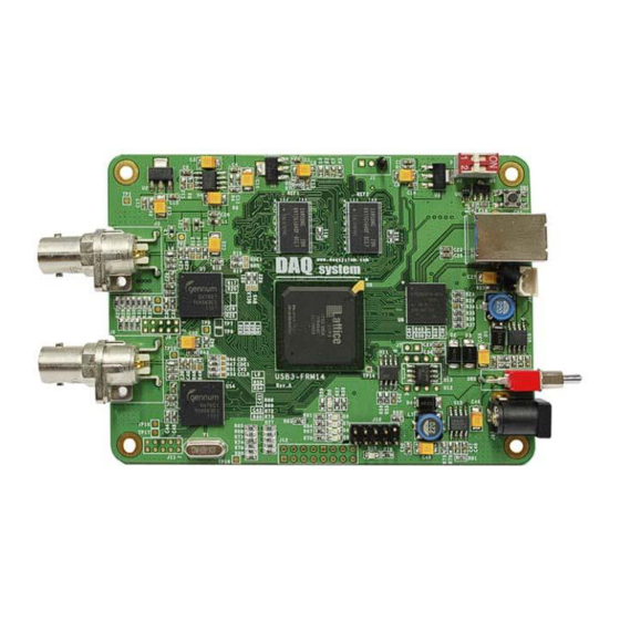
USB3-FRM14 User’s Manual 2-2 USB3-FRM14 Board Layout In this chapter, the primary functions of the USB3-FRM14 board are described briefly. For more information, refer to the device specification USB3-FRM14 Board REF1 REF2 123 789 123 789 www.daqsystem.com system USB3-FRM14 Rev. A [Figure 2-2. -
Page 9: Device Features
USB3-FRM14 User’s Manual 2-3 Device Features (1) BNC Connecter : J3, J8 Caution) You should be used to connect the J8(Channel 0) connector at first. (2) SDI Receiver : U7, U14 Receive the SDI Data. (3) FPGA : U9 All of the board functions are controlled by the Logic program of the FPGA. -
Page 10: Connector Pin Out
USB3-FRM14 User’s Manual 2-4 Connector Pin-out The board has several connectors and jumpers to set. The USB3-FRM14 board is equipped with two main connecters, USB3 B-type connector for USB connection and BNC connecter J3 and J8. 2-4-1 CN1 Connecter The USB3-FRM14 has a USB-B type connector for high speed USB connection. -
Page 11: J1 Connector
Rx (Receiver Data) Ground 2-4-3 J2 Switch USB3-FRM14 board is designed of four maximum USB3-FRM14 boards at the same time so as usable. Distribution of each board sets it up through 4 pin switch (J2) in a board. [Figure 2-5. J2 Switch] [Table 5. -
Page 12: J3, J8 Bnc Connector
USB3-FRM14 User’s Manual 2-4-4 J3, J8 BNC Connecter BNC(Bayonet Neil-Concelman) connecter is a miniature quick connect/disconnect RF connecter used for coaxial cable. It features three part of cable, at the center of the signal lines and coax internal signal that surround outer conductor (shield), and insulation. BNC connecters are made to match the characteristic impedance of cable at either 50 ohms or 75 ohms. -
Page 13: J9 Connector
USB3-FRM14 User’s Manual 2-4-6 J9 Connecter External 12V DC Jack Power Connector of DC-005(2.0) type. The central part of the DC Jack is +12 V. 1.0A [Figure 2-8. Rated Output] 2-4-7 J10 Connecter The J9 connector is used for the FPGA program upgrade. Never use it at the normal operation. -
Page 14: Sw1
USB3-FRM14 User’s Manual 2-4-8 SW1 3.3V Power Reset Switch. SW_RST 3.3V [Figure 2-10. SW1 Switch] 2-4-9 SW2 Board Power (5V from USB or Power Generator) On/Off Switch. When the switch is Up state, power(5V) is On. 5V from USB 5V from Regulator 5.0V... -
Page 15: Ancillary Data
USB3-FRM14 User’s Manual 2-5 Ancillary Data USB3-FRM14 board can show Vertical Ancillary Data (VANC). Ancillary Data(commonly abbreviated as ANC Data), in the context of television system, refers to a means which by non-video information(such as audio, other forms of essence, and metadata). - Page 16 USB3-FRM14 User’s Manual Depending on the configuration of the ANC Packet is divided into Type1 and Type2. Type 2 (Up to 255 bytes Max.) Type 1 [Figure 2-13. ANC Packet Structure] (1) ADF --- Ancillary Data Flag always start sequence is 0x000, 0x3FF, 0x3FF (b9..b0 : in case of 10-bit) or 0x00, 0xFF, 0xFF(b7..b0 : in case of 8-bit).
- Page 17 USB3-FRM14 User’s Manual (2) DID --- Data Identification word indicates the type of ancillary data that the packet corresponds to. Data identifiers range from 0 to 255, with 0 being reserved. A Serial Data Interface is a 10-but format, the DID word is enclosed as follows:...
- Page 18 USB3-FRM14 User’s Manual (4) DBN --- The Data Block Number is only valid if the DID is 127(80 hex) or greater. It is used to identify multiple packets of the same type within a field. The DBN is an 8-bit value, encoded in the same fashion as the SDID.
-
Page 19: Installation
Hot-Plug and Plug & Play. Therefore, you can install it easily. The required PC operating system for the USB3-FRM14 is Windows XP SP1 higher or Windows 7. The USB3-FRM14 uses USB Super Speed interface thus “xxx USB 3.0 Root Hub” should be installed in your PC. - Page 20 USB3-FRM14 User’s Manual The item “USB 3.0 Root Hub” should be shown in the “Device Manager” window as shown in [Figure 3-1]. After checking the PC environmental conditions for USB3-FRM14, do the following steps to install the board (1) Install the USB3-FRM14 board into your system.
- Page 21 USB3-FRM14 User’s Manual [Figure 3-3. Specify the driver folder] Select “Search for the best driver in these locations”. Check “Search removable media (floppy, CD- ROM)”. Check “include this location in the search”. Click “Browse” button. Select the folder where the drivers are located.
- Page 22 USB3-FRM14 User’s Manual [Figure 3-4. Warning window] When you across a window’s warning message regarding to the compatibility problem as shown the [Figure 3-4] during the installation process, just click “Continue” button and go on the installation.
- Page 23 USB3-FRM14 User’s Manual If the installation is completely finished, a completion window message shall be shown as in [Figure 3-5]. Click “Finish”. [Figure 3-5. “Completion” message window]...
- Page 24 Grabber #14 Board” in the “Device Manager” window as shown in [Figure 3-6]. [Figure 3-6. “Device Manager” window] If you can see the “DAQ system USB3.0 Frame Grabber #11 Board” at the Universal Serial Bus controllers, the driver installation is to have been over. (Check the red circle)
-
Page 25: Sample Program
USB3-FRM14 User’s Manual 4. Sample Program In the Exe folder of the CDROM provided with the board, a sample program “FrameTest.exe” is provided for easy use of the board. By displaying Frame Data as hexadecimal values, it is stored in memory or hard disk so that developers can utilize the frame data needed. -
Page 26: Image Function
All files specified above are included on the supplied CDROM. In order to run the sample program normally, the API DLL (USB3-FRM14.DLL) must be in the folder of the executable file or in the Windows system folder or the folder specified by the Path environment variable. - Page 27 USB3-FRM14 User’s Manual Writing Method : Little Endian (In case of 10bit YUV) 26 25 16 15 10 9 One Frame Data size is as follow equation. case 0 (8bit): nSize = nXres * nYres case 1 (16bit): nSize = nXres * nYres * 2...
- Page 28 USB3-FRM14 User’s Manual [Figure 4-2. Image File Hex Value] (9) “Auto” toggle When check this box, it displays a video (10) “Skip” toggle When press this button, it displays a freeze-frame. (11) “Full screen” toggle It shows full screen. (12) “Half tone” toggle Select the Half tone mode filter.
-
Page 29: Anc Data Function
USB3-FRM14 User’s Manual 4-2 ANC Data Function (Notice) Chapter 5 Test is more detailed description. (1) “Board #” Selection It selects a board number in case of the multi USB3.0 boards. It can select 0 ~ 4 at currently. (2) “Get Version” button It shows the version of FPGA and Firmware. - Page 30 USB3-FRM14 User’s Manual (3) “Vanc Mode” Select the VANC mode. Disable : VANC mode of each channel is not used. Y Vanc : The Vanc data is added to the Y packet of video of the configuration of the YCbCr.
-
Page 31: Image Save Function
OS), binary file in frame unit in D:\Image (or the folder selected by the user: Select Folder) specified below. Save # next to it shows the number of saved frames. When AVI is selected, D:\USB3-FRM14_IMG\usb3-frm14.avi is saved as MPEG4. Folders are fixed. It is possible to use the change after modifying the folder in the source. -
Page 32: Test
And, USB3-SDI01 is a simulator board for VANC data signal, it is changed SDI signal from the data of USB3-DIO01 and transmits the USB3-FRM14 board. Make sure that the VANC data is received correctly by connecting the USB3-DIO01 board USB3-SDI01 board as in [Figure 5-1]. HD-SDI camera is used the two cameras that support the 1080p (1920x1080 @ 30fps). -
Page 33: Image Test
5-1 Image Test First, the Frame Test program is shown in [Figure 5-2] after connect the camera to the J8 connector of USB3-FRM14 board. (Notice) The running order for the sample program as Check the Board # “Device Open” click “Device Init” click ... - Page 34 USB3-FRM14 User’s Manual [Figure 5-3] below is the screen when “Half tone” is selected for image improvement. [Figure 5-3. “CH 0” Picture quality improvement screen]...
- Page 35 USB3-FRM14 User’s Manual [Figure 5-4] is the screen when you select the "Full Scree". Select the Full Screen, and a larger window, it is possible to see the resolution entire selected. Sometimes Frame Rate varies according to the system specifications.
- Page 36 USB3-FRM14 User’s Manual [Figure 5-5] below shows the screen when two channels are selected. Frame rate may change depending on system specifications. [Figure 5-5. When two channel select (Windows XP 32bit)] (Notice) When sometimes the application program downs and there is only one video on the screen, we recommend that you use to connect the connector external power(12V DC) to J9 connector.
- Page 37 USB3-FRM14 User’s Manual [Figure 5-6] below shows two channels in Windows 7 64bit O.S. This is the screen when tested. F/R (Frame Rate) is 65 frames, and images from two SDI cameras of 30 frames each can be viewed on each channel. However, if the “Half tone” filter is used to see the image well, the frame rate may change depending on the system specifications.
- Page 38 USB3-FRM14 User’s Manual [Figure 5-7. When using the two channel (Windows 7 64-bit), Using half tone] In conclusion, comparing [Figure 5-5] and [Figure 5-7], frame rate can be changed according to system requirements. Windows 7 testing is better than Windows XP, and testing in a 64-bit OS...
-
Page 39: Vanc Test
USB3-FRM14 User’s Manual 5-2 VANC Test The board connection for VANC implementing is as [Figure 5-8]. USB3-DIO01 USB3.0 USB3-FRM14 Interface USB3.0 Data Interface VANC Data USB3-SDI01 Board Connection [Figure 5-8. Board Connection] First, if you look at the program that runs in USB3-DIO01 and sends VANC data to the output... - Page 40 USB3-FRM14 User’s Manual [Figure 5-9. VANC Data Transmit Program] That command description is as follows. Device Open --- Open the device. It is performed only once in the beginning. Device Init --- Current device that attached to the system is initialized.
- Page 41 0 when “Vanc Out” is pressed in [Figure 5-9]. In [Figure 5-9], it can be seen that the value when the set value is transmitted to Vanc Out is written in each VANC data column of VANC CH0 at the upper left. (check the red circle) [Figure 5-10. USB3-FRM14 Frame Test]...
- Page 42 USB3-FRM14 User’s Manual Up to 4 VANC data of channel 0 or 1 can be received. Only the first and second VANC data are displayed on the screen, and the user can expand up to four if necessary. The ANC data packet includes a header part, other packet information, and 255 bytes of user data UDW (User Data Words), with a total interval of 512 bytes.
- Page 43 USB3-FRM14 User’s Manual [Figure 5-11] shows the USB3-FRM14 Frame Test screen when video data is received from channel 0 and VANC data is received from channel 2. You can see that the value when the video comes in through the BNC connector (J8) on the upper right and the value set in [Figure 5-7] is...
- Page 44 USB3-FRM14 User’s Manual [Figure 5-12] shows the USB3-FRM14 Frame Test screen when video data is received from channel 2 and VANC data is received from channel 0. You can see that the value when the video comes in through the BNC connector (J8) in the lower right corner and the value set in [Fig. 5-7] is transmitted to the Vanc Out is written in the data column for each VANC of VANC CH2 in the upper left corner.
-
Page 45: Appendix
USB3-FRM14 User’s Manual Appendix A-1 Board Size The external dimensions of the board are as follows. (For detailed dimensions, please ask the person in charge.) -
Page 46: Repair Regulations
Thank you for purchasing a DAQ SYSTEM product. Please refer to the following regarding Customer Service regulated by DAQ SYSTEM. (1) Read the user manual before using the DAQ SYSTEM product and follow the instructions. (2) When returning the product to be repaired, please write down the symptoms of the failure and send it to the head office. -
Page 47: References
1. USB 3.0 System Architecture -- Don Anderson, USB SIG(www.usb.org) 2. Universal Serial Bus Specification -- Compaq/Intel/Microsoft/NEC, MindShare Inc. (Addison Wesley) 3. AN201 How to build application using API -- DAQ system 4. AN342 USB3-FRM14 API Ver1.0 -- DAQ system... - Page 48 USB3-FRM14 User’s Manual MEMO Contact Point Web sit : https://www.daqsystem.com Email : postmaster@daqsystem.com...
Need help?
Do you have a question about the USB3-FRM14 and is the answer not in the manual?
Questions and answers