Table of Contents
Advertisement
Quick Links
PCIe-FRM16
User Manual
Version 1.3
ⓒ 2005 DAQ SYSTEM Co., Ltd. All rights reserved.
Microsoft® is a registered trademark; Windows®, Windows NT®, Windows XP®, Windows 7®, Windows 8®, Windows 10®
All other trademarks or intellectual property mentioned herein belongs to their respective owners.
Information furnished by DAQ SYSTEM is believed to be accurate and reliable, However, no responsibility is assumed by DAQ SYSTEM for its use, nor
for any infringements of patents or other rights of third parties which may result from its use. No license is granted by implication or otherwise under
any patent or copyrights of DAQ SYSTEM.
The information in this document is subject to change without notice and no part of this document may be copied or reproduced without the prior
written consent.
Advertisement
Table of Contents

Related Manuals for DAQ system PCIe-FRM16


Summary of Contents for DAQ system PCIe-FRM16
- Page 1 All other trademarks or intellectual property mentioned herein belongs to their respective owners. Information furnished by DAQ SYSTEM is believed to be accurate and reliable, However, no responsibility is assumed by DAQ SYSTEM for its use, nor for any infringements of patents or other rights of third parties which may result from its use. No license is granted by implication or otherwise under any patent or copyrights of DAQ SYSTEM.
-
Page 2: Table Of Contents
PCIe-FRM16 User’s Manual Contents 1. Introduction -------------------------------------------------------------------------- 1-1 Product Features ------------------------------------------------------------------------- 1-2 Product Application ------------------------------------------------------------------------- 2. PCIe-FRM16 Board Function 2-1 FPGA Block Diagram ----------------------------------------------------------------------- 2-2 DVI(Digital Video Interface) -------------------------------------------------------------- 3. PCIe-FRM16 Board Description 3-1 Board Layout ------------------------------------------------------------------------ 3-2 Device Features... -
Page 3: Introduction
PCIe-FRM16 User’s Manual 1. Introduction PCIe-FRM16 is a board that receives DVI (Digital Visual Interface) signal and transmits it to PC using PCI Express 4x interface method. Various resolutions such as 640x480, 800x600, 1024x768, 1920x1080 and 1920x1200 are supported. It supports up to 1920x1200 per channel and can handle two DVI signals at the same time. -
Page 4: Product Features
PCIe-FRM16 User’s Manual 1-1 Product Features Items Description Remark Hardware PC Interface PCI Express 4x Operation Power PC Power +3.3V (Max 1.1A) +12V (Max 1A). Video Interface 2 Ports Single DVI Feature Full HD 1080P at 12fps MAX 1920x1200 resolution... -
Page 5: Pcie-Frm16 Board Function
2. PCIe-FRM16 Board Function 2-1 FPGA Block Diagram In the case of PCIe-FRM16, FPGA Core Logic is in charge of overall control. It receives RGB, HDMI (High-Definition Multimedia Interface), and DVI (Digital Visual Interface) signals as its main function and delivers it to the PC. - Page 6 PCIe-FRM16 User’s Manual 2-2 DVI (Digital Visual Interface) DVI (Digital Visual Interface) is divided into DVI-D (Digital Only), DVI-A (Analog Only), and DVI-I (Integrated Digital & Analog) methods. The PCIe-FRM14 board supports DVI-I type DVI, so it is compatible with the existing analog type methods. Also, HDMI (High Definition Multimedia Interface) that uses the same format of digital image data can be used together by using the DVI to HDMI gender.
- Page 7 PCIe-FRM16 User’s Manual The data format of DVI is based on the Panel Link serial signal line. DVI uses a digital transmission protocol that is Transition Minimized Differential Signaling (TMDS) as shown in [Figure 2-2]. TMDS is composed of TMDS Transmitter and TMDS Receiver, and a Transmitter is mounted on the graphic card side and a Receiver is mounted on the monitor side to transmit digital data from the graphic card to the monitor.
- Page 8 PCIe-FRM16 User’s Manual PCIe-FRM16 supports single DVI as shown in [Figure 2-4]. PCIe-FRM16 board supports DVI-I type DVI, so it is compatible with existing analog type methods. can [Refer to 3-3 for DVI connector and signal line] Control signal line consists of LVAL (Line Valid), FVAL (Frame Valid), DVAL (Data Valid) and clock, and transmits the valid horizontal and vertical resolution and data of the image to be transmitted according to the clock.
-
Page 9: Pcie-Frm16 Board Description
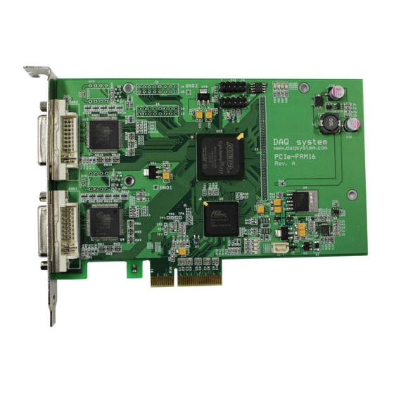
PCIe-FRM16 User’s Manual 3. PCIe-FRM16 Board Description Each important board function is briefly described. For detailed function information, please refer to the parts specification. 3-1 PCIe-FRM16 Board Layout [Figure 3-1. PCIe-FRM16 Layout] There are a total of nine LEDs on the board, and the description of each is as follows. -
Page 10: Device Features
PCIe-FRM16 User’s Manual 3-2 Device Features (1) FPGA : U12 All of the board functions are controlled by the Logic program of the FPGA. (2) DVI Receiver : U4, U13 It is receiving DVI Data and transmitting to FPGA. (3) Regulator : U2, U3, U7, U9, U11, U15, U16 This block is for supplying the power to the board. -
Page 11: Connector Pin Out
PCIe-FRM16 User’s Manual 3-3 Connector Pin-out The connectors and jumpers used in PCIe-FRM16 will be described. The main connectors are DVI connectors CON1 and CON2 connectors for DVI connection. [Figure 3-2] shows the bracket that interfaces with the board and the connection connector. - Page 12 [Figure 3-3] below shows the pin map of the CON1 and CON2 connectors on the board. All pin specifications are input/output based on the DVI standard, so please refer to the DVI standard document for details. [Figure 3-3. PCIe-FRM16 CON1, CON2 Connector Pin-out] [Table 1. CON1, CON2 DVI Connector] Pin #...
- Page 13 PCIe-FRM16 User’s Manual +5V Power Power for monitor standby Pin 14 and regression for synchronization Hot Plug Detect TMDS Data0- Digital Blue- (Link 1) TMDS Data0+ Digital Blue+ (Link 1) TMDS Data0/5 Shield TMDS Data5- Digital Red- (Link 2) TMDS Data5+...
-
Page 14: Installation
PCIe-FRM16 User’s Manual 4. Installation 4-1 Product Contents Before installing the board, check that the contents of the package are intact. 1. PCIe-FRM16 Board 2. CD (Drivers/Manual/API/Sample source etc.) Document Folder : Manual and Catalog Driver Folder : pcie_frm16.sys pcie-frm16.inf... -
Page 15: Installation Process
The board environment must be Windows 2000 SP4 or higher and Windows XP SP1 or higher. First, turn off the PC's power, plug the PCIe-FRM16 board into the PCI Express Slot, and turn on the PC's power. When the “Start New Hardware Wizard” window opens as shown below, select as shown below and click the Next button. - Page 16 PCIe-FRM16 User’s Manual 2. Select Driver from the enclosed CD and click the Next button. 3. Click the Next button. It indicates that the installation process is proceeding as shown below. The driver folder contains “pcie_frm16.inf” and “pcie_frm16.sys” files required for driver...
- Page 17 5. PCIe-FRM16_B has two DVI devices, so the above is done twice. 6. When the installation is complete, check whether the driver is installed normally in the following way. 7. In My Computer -> Properties -> Hardware -> Device Manager, check if the Multifunction Adapter -> “PCIe-FRM16” is installed.
- Page 18 8. If it appears as shown in the figure below, the installation has been completed normally. If you can see the “PCIe-FRM16” at Multifunction Adaptors, the driver installation is to have been over. (Check the red circle. And it must be displayed two drivers of PCIe-FRM16_B.)
-
Page 19: Sample Program
PCIe-FRM16 User’s Manual 5. Sample Program Sample programs “FrmTest” and “FrameView” are provided in the TestApp folder of the CDROM provided with the board for easy use of the board. First, “FrmTest.exe”, one of the executable files, displays Frame Data as a hexadecimal value and stores it in memory or hard disk so that developers can utilize the necessary frame data, and “FrameView.exe”... - Page 20 PCIe-FRM16 User’s Manual API (Application Programming Interface) is required to use the above sample program. API is provided in the form of “DLL”, and import library and header file are required for compilation. All files specified above are included on the supplied CDROM. In order to run the sample program normally, the API DLL (PCIe-FRM16_B.DLL) must be in the folder of the executable file or...
- Page 21 PCIe-FRM16 User’s Manual (11) “Auto View” click When checked, the video is displayed. (12) Frame Rate It shows the frame/sec of the video. (13) “Auto Save” button When checked, it is saved as a file in BMP or JPEG format in the box below.
-
Page 22: Frameview Program
Windows system folder or the folder specified by the Path environment variable. [Figure 5-2] is a screen captured by connecting PCIe-FRM16 to the DVI connector of the graphic card of another system and executing “FrameView.exe” to capture the image displayed... - Page 23 PCIe-FRM16 User’s Manual The description of each menu bar is as follows. (1) Select resolution Display resolution – Select according to the input resolution Reverse --- Reverse On/Off (Not currently supported) (2) Save --- Saved in D:\frame.dat (fixed). (3) Stop --- Stop saving.
- Page 24 PCIe-FRM16 User’s Manual (9) Clear Frame --- When press this button, it will be clear current frame. (10) Get Frame --- Get a just one frame. (11) Frame Auto Read --- When check this box, it get a frame continuously until re-check.
-
Page 25: Appendix
PCIe-FRM16 User’s Manual Appendix Board Size The external sizes of the board are as follows. For detailed dimensions, please contact the person in charge. -
Page 26: Repair Regulations
⑥ Products whose serial number has been changed or removed intentionally ⑦ If DAQ SYSTEM determines that it is the customer's fault for other reasons (5) Shipping costs for returning the repaired product to DAQ SYSTEM are the responsibility of the customer. -
Page 27: References
1. PCI Local Bus Specification Revision2.1 -- PCI Special Interest Group 2. How to install PCI DAQ Board -- DAQ system 3. AN201 How to build application using API -- DAQ system 4. AN312 PCIe-FRM16 API Programming -- DAQ system... - Page 28 PCIe-FRM16 User’s Manual MEMO Contact Point Web sit : https://www.daqsystem.com Email : postmaster@daqsystem.com...
Need help?
Do you have a question about the PCIe-FRM16 and is the answer not in the manual?
Questions and answers