Advertisement
Quick Links
cPCI-SBC01
Windows, Windows2000, Windows NT and Windows XP are trademarks of Microsoft. We acknowledge that the
trademarks or service names of all other organizations mentioned in this document as their own property.
Information furnished by DAQ system is believed to be accurate and reliable. However, no responsibility is assumed by DAQ
system for its use, nor for any infringements of patents or other rights of third parties which may result from its use. No license is
granted by implication or otherwise under any patent or copyrights of DAQ system.
The information in this document is subject to change without notice and no part of this document may be copied or
reproduced without the prior written consent.
(EMB-CPU01)
User's Manual
Copyrights
2007 DAQ system, All rights reserved.
1-
-
cPCI-SBC01 Board
User manual
http://www.daqsystem.com
Advertisement

Related Manuals for DAQ system cPCI-SBC01


Summary of Contents for DAQ system cPCI-SBC01
- Page 1 Information furnished by DAQ system is believed to be accurate and reliable. However, no responsibility is assumed by DAQ system for its use, nor for any infringements of patents or other rights of third parties which may result from its use. No license is granted by implication or otherwise under any patent or copyrights of DAQ system.
-
Page 2: Table Of Contents
User manual Contents 1 . cPCI-SBC01 Introduction 2 . cPCI-SBC01 Appearance 3 . cPCI-SBC01 Assembly (Memory, Hard Disk) 4 . Peripheral Device Control through Compact PCI Interface(Back-Plane Connection) 5 . Expansion Port through Transition Board 6 . WINDOWS & Driver Installation... -
Page 3: Cpci-Sbc01 Introduction
Board User manual 1 . cPCI-SBC01 Introduction Introduction It is the low cost Single Board Computer(SBC) which equipped a low power and low heat processor. It provides solution to be suitable for Embedded market wanting low power and small size. -
Page 4: Cpci-Sbc01 Appearance
SW,VGA,Network,USB Rear side Compact PCI interface The cPCI-SBC01 board can use to personal PC with the external Power +5V. In front side of the cPCI-SBC01 have the Connector Out (VGA, Power S/W, Ethernet, 2xUSB, Power LED, Audio-Jack). - The cPCI-SBC01 board connects the Back-Plane at rear side. It can control the other devices through compact PCI interface http://www.daqsystem.com... -
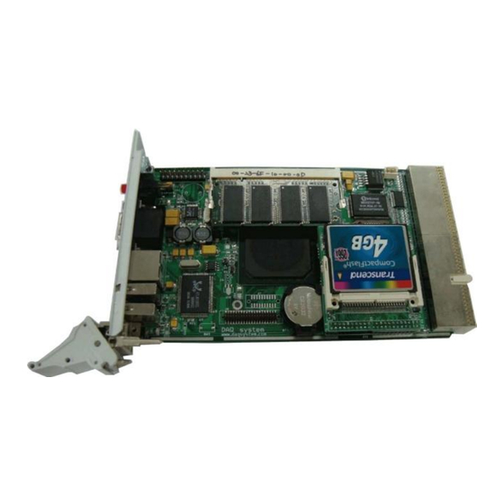
Page 5: Cpci-Sbc01 Assembly(Memory, Hard Disk)
Board User manual 3 . cPCI-SBC01 Assembly(Memory, Hard Disk) 1. Memory(SODIMM – SDRAM) Connection - Memory Connection with J4 connector(256M ~ 1G) - CF card connector board (It is necessary to change the board if it connects 1.8” hard.) - Page 6 Board User manual - Hard Disk Connection (This picture is CF card connection.) Notice) It is necessary to change the board if it connects 1.8” hard. The picture shows differently above picture http://www.daqsystem.com...
-
Page 7: Peripheral Device Control Through Compact Pci
Board User manual 4 .Peripheral Device Control through Compact PCI Interface(Back-Plane) cPCI-SBC01 Switch Audio Usage – Our Product cPCI-EK01 Ethernet 2xUSB The cPCI-SBC01 can control the other Compact PCI products as to connect Back- Plane like above picture. http://www.daqsystem.com... -
Page 8: Interface(Back-Plane Connection)
User manual 5 . Expansion Port through Transition B’d 2xUSB RS232 Expansion rear 2xPS2 interface serial The transition board can use through the Back-Plane. And It is possible to use the expansion ports with connect the cPCI-SBC01. (Special Purchase) http://www.daqsystem.com... -
Page 9: Windows & Driver Installation
Board User manual 6 . WINDOWS & Driver Installation To connect a USB KEYBOARD and USB MOUSE and USB CD-ROM(WINDOWs CD) at Board. And, connect the power(5V, 3A) after connection to a DSUB 15 PIN VGA PORT and light up the switch. - Page 10 Board User manual 5. After choose the “Save values and Exit”, and escape the display. 6. Booting is performed with a USB CD-ROM, you are able to progress a windows install guide. 7. After finished the Windows installation, you have to install the last Board driver.
- Page 11 Board User manual TouchWare at the wallpaper. - Double click the TouchWare. - Click the “HW Info”. - Click the “Auto Search Touch” button, check the connection port. - After finding the port at Touch Controller, press “OK”. - Choose the “Calibrate” button.
- Page 12 Board User manual - When show the below display, press the lighting point. (You should continuously press until completed progress bar.) - Press “Yes”, and then finished the install. The optimum display set for the LCD - Change the resolution 800x400 because LCD resolution is optimum 800x480.
- Page 13 Board User manual - Choose the “Property” in wallpaper. - Click the “Advancd” in “Setting” in “Display Registration Information” display. - Click the “List All Modes” in “Adaptor” - Choose the “800 x 480 true color”. - Press “OK” and hit “Execute”.
Need help?
Do you have a question about the cPCI-SBC01 and is the answer not in the manual?
Questions and answers