Table of Contents
Advertisement
Quick Links
USB3-DIO01
User Manual
Version 1.4
ⓒ 2005 DAQ SYSTEM Co., Ltd. All rights reserved.
Microsoft® is a registered trademark; Windows®, Windows NT®, Windows XP®, Windows 7®, Windows 8®, Windows 10®
All other trademarks or intellectual property mentioned herein belongs to their respective owners.
Information furnished by DAQ SYSTEM is believed to be accurate and reliable, However, no responsibility is assumed by DAQ SYSTEM for its use, nor
for any infringements of patents or other rights of third parties which may result from its use. No license is granted by implication or otherwise under
any patent or copyrights of DAQ SYSTEM.
The information in this document is subject to change without notice and no part of this document may e copied or reproduced without the prior
written consent.
Advertisement
Table of Contents

Subscribe to Our Youtube Channel
Related Manuals for DAQ system USB3-DIO01


Summary of Contents for DAQ system USB3-DIO01
- Page 1 All other trademarks or intellectual property mentioned herein belongs to their respective owners. Information furnished by DAQ SYSTEM is believed to be accurate and reliable, However, no responsibility is assumed by DAQ SYSTEM for its use, nor for any infringements of patents or other rights of third parties which may result from its use. No license is granted by implication or otherwise under any patent or copyrights of DAQ SYSTEM.
-
Page 2: Table Of Contents
-------------------------------------------------------------------------- 1-1 Product Features ------------------------------------------------------------------------- 1-2 Product Application ------------------------------------------------------------------------- 2. USB3-DIO01 Board Function 2-1 Block Diagram ------------------------------------------------------------------------ 2-2 USB3-DIO01 & ADP-CA01 connection ------------------------------------------------- 3. USB3-DIO01 Board Description 3-1 USB3-DIO01 Board Layout ----------------------------------------------------------------- 3-2 Device Features --------------------------------------------------------------------- 3-3 Connector Pin out... - Page 3 USB3-DIO01 User’s Manual 5. Sample Program ------------------------------------------------------------------------ 5-1 Image Frame Function ---------------------------------------------------------------- 5-2 Camera Function ------------------------------------------------------------------- DIO Function --------------------------------------------------------------------- I2C Function -------------------------------------------------------------------- Appendix A-1 Board Size --------------------------------------------------------------------- A-2 Repair Regulations --------------------------------------------------------------------- References ------------------------------------------------------------------------...
-
Page 4: Introduction
USB3-DIO01 User’s Manual 1. Introduction USB3-DIO01 board is a board used by connecting a daughter board in the form of a base board. [Figure 1-1] shows an example of using the daughter board ADP-CA01. USB3-DIO01 transfers the video image received from the PC through the USB3.0 interface through the ADP-CA01 board at the bottom. -
Page 5: Product Features
USB3-DIO01 User’s Manual 1-1 Product Features Items Description Remark Hardware PC Interface USB 3.0 B-Type Operation Power +12VDC/650mA External 12V DC Power (A6-Type : 5.5x2.1mm) Video Interface Camera Link Output ADP-CA01 Feature Interface On-board Memory 128MB (DDR2) x2 Communication Simultaneous use of Max. -
Page 6: Usb3-Dio01 Board Function
2. USB3-DIO01 Board Function 2-1 Block Diagram As shown in the figure below, in the case of USB3-DIO01, FPGA Core Logic is in charge of overall control. The main function is to transmit Image Frame Data to the connector through the External I/O connector. -
Page 7: Usb3-Dio01 & Adp-Ca01 Connection
Second, it is used by connecting with the ADP-CA01 board through the 50-pin External I/O connector inside the board. USB3-DIO01, which receives PC's Image Frame Data at high speed, transmits image information to ADP-CA01, and ADP-CA01 board converts the image signal according to Camera Link specification and transmits it to the outside through Camera Link connector. -
Page 8: Usb3-Dio01 Board Description
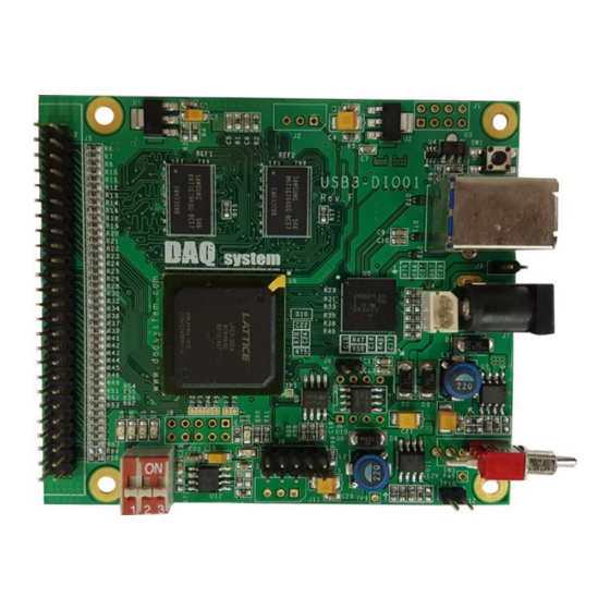
USB3-DIO01 User’s Manual 3. USB3-DIO01 Board Description 3-1 USB3-DIO01 Board Layout USB3-DIO01 Board REF1 REF2 123 789 123 789 USB3-DIO01 Rev. E DAQ Sysytem 1 2 3 [Figure 3-1. USB3-DIO01 Layout] There are six important LEDs on the board, each of which is described below. -
Page 9: Device Features
USB3-DIO01 User’s Manual 3-2 Device Features Each board function will be briefly described. For detailed function information, please refer to the parts specification. (1) FPGA : U6 All of the functions are controlled by the logic program of the FPGA. -
Page 10: Connector Pin Out
USB3-DIO01 User’s Manual 3-3 Connector Pin-out This section describes the connectors and jumpers used in USB3-DIO01. The main connectors are CN1, a USB-B type connector for USB connection, and J5, which receives external I/O and image frames. 3-3-1 CN1 Connector [Figure 3-2] shows the PIN of the USB3.0 standard powered-B type connector on the... -
Page 11: J2 Connector
USB3-DIO01 User’s Manual 3-3-2 J2 Connector It is a connector that can interface with USB 3.0 SIE (U5) from the outside through I2C. In the idle state of I2C, the bus is always high. [Figure 3-3. J2 Connector (Top View)] [Table 2. - Page 12 USB3-DIO01 User’s Manual DIO_6 Digital Input/Output 6 DIO_7 Digital Input/Output 7 DIO_8 Digital Input/Output 8 DIO_9 Digital Input/Output 9 DIO_10 Digital Input/Output 10 DIO_11 Digital Input/Output 11 DIO_12 Digital Input/Output 12 DIO_13 Digital Input/Output 13 DIO_14 Digital Input/Output 14 DIO_15...
-
Page 13: J7 Connector
USB3-DIO01 User’s Manual Ground Ground Note) 12V is not applied to pin 45 to boards below Rev C. 3-3-4 J7 Connector DC-005(2.0) standard external 12V DC Jack power connector. If the USB power is insufficient, the program may crash or the video may not appear. Use this connector when power is insufficient. -
Page 14: Sw1 Switch
[Figure 3-7. Switch SW1] 3-3-7 J10 Switch The USB3-DIO01 board is designed so that up to 8 USB3-DIO01 boards can be used simultaneously in one system (PC). Each board classification can be set through the 4- pin DIP switch (J10) in the board. -
Page 15: Installation
Hot-Plug and Plug & Play. Therefore, you can install it easily. The required PC operating system for the USB3-DIO01 is Windows 2000 SP4 or Windows XP SP1 higher. The USB3-DIO01 uses USB Super Speed interface thus “xxx USB 3.0 Root Hub”... - Page 16 (1) Install the USB3-DIO01 board into your system. (2) Power on the frame grabber. (3) Confirm the LED (D8) and LED (D10) on the USB3-DIO01 board turns on. (4) After check the power, Connect USB3 A-B cable between the case and your PC.
- Page 17 USB3-DIO01 User’s Manual [Figure 4-2. “Hardware Wizard” window] If new hardware is found, Wizard will ask you to install the corresponding driver, For installation of the driver, select item “Install from a list or specific location(Advanced)” and click “Next” as in...
- Page 18 USB3-DIO01 User’s Manual [Figure 4-3. Specify the driver folder] Select “Search for the best driver in these locations”. Check “Search removable media (floppy, CD- ROM)”. Check “include this location in the search”. Click “Browse” button. Select the folder where the drivers are located.
- Page 19 USB3-DIO01 User’s Manual [Figure 4-4. Warning window] When a window’s warning message will be appeared regarding the compatibility problem as shown the [Figure 4-4] during the installation process, just click “Continue” button and go on the installation.
- Page 20 USB3-DIO01 User’s Manual If the installation is completely finished, a completion window message shall be shown as in [Figure 4-5]. Click “Finish”. [Figure 4-5. “Completion” message window]...
- Page 21 I/O #01 Board” in the “Device Manager” window as shown in [Figure 4-6]. [Figure 4-6. “Device Manager” window] If you can see the “DAQ SYSTEM USB3.0 Digital I/O #01 Board” at the Universal Serial Bus controllers, the driver installation is to have been over. (Check the red circle)
-
Page 22: Sample Program
All files specified above are included on the supplied CDROM. In order to run the sample program normally, the API DLL (USB3-DIO01.DLL) must be located in the folder of the executable file or in the Windows system folder or the folder specified by the Path environment variable. -
Page 23: Image Frame Function
USB3-DIO01 User’s Manual 5-1 Image Frame Function (1) “Device Open” button It starts a selected board device. If the value is "0", the device is not connected or no device. (2) “Device Close” button It closes the Device. (3) “LVDS Init” button Video Data Mode to 8bit, 16bit, 24bit, 32bit, 16bit YUV of image frames, and then initialize the function of receiving image frame data. -
Page 24: Camera Function
USB3-DIO01 User’s Manual (11) “Auto” toggle When check this box, it displays a video. (12) “Skip” toggle When check this box, it displays a stop image related “Auto”. (13) “Rate: Frame” It shows a frame number per second. 5.2 Camera Function Caution) This is the function description, when a function is selected as USB Output. - Page 25 USB3-DIO01 User’s Manual (4) Select Output Resolution Output the desired resolution value. User can set valid active frame Horizontal, Vertical Size to Total, Front porch, back It can also be output by adjusting the porch value. You can specify a new resolution by manually specifying the desired values for Hsize, DE, and Vsize.
- Page 26 USB3-DIO01 User’s Manual [Figure 5.3 V_RES, V_BLK and D_RES, D_BLK Relation] (5) “Output Size Set” button Store the value selected above. Press the button to change the output resolution when you need to save. (6) Select Output Data Below figure is the result of the test with our USB3-FRM13_B.
- Page 27 USB3-DIO01 User’s Manual This is the display when “Patt” assigned the “file”. [Figure 5.5 USB3-FRM13_B “Frame View” Capture Display] Constant --- Outputs a constant value of the specified pattern. [Figure 5.6 USB3-FRM13_B “Frame Read” Capture Display]...
- Page 28 USB3-DIO01 User’s Manual [Figure 5.7 USB3-FRM13_B “Frame View” Capture Display] hcnt --- Output a value of Horizontal Count. [Figure 5.8 USB3-FRM13_B “Frame Read” Capture Display]...
- Page 29 USB3-DIO01 User’s Manual [Figure 5.9 USB3-FRM13_B “Frame View” Capture Display] Pixel Count --- Output a value of Pixel Count. For example) If the resolution is640x480, output 0 ~ 4B000 (307200 pixels). [Figure 5.10 USB3-FRM13_B “Frame Read” Capture Display]...
- Page 30 USB3-DIO01 User’s Manual [Figure 5.11 USB3-FRM13_B “Frame View” Capture Display] (7) Select “R_B Swap” Below figure is the result of the test with our USB3-FRM13_B. When R_B button is selected, the Red and Blue signal value is exchanged as shown in the...
- Page 31 USB3-DIO01 User’s Manual [Figure 5.12 USB3-FRM13_B Capture Display] (8) “Patt” Selection Select the output data pattern (Pattern). To perform this command, you must be selected "Select Output Data - USB Data". Nature --- Output the value of the specified data.
-
Page 32: Dio Function
USB3-DIO01 User’s Manual 5.3 DIO Function (1) “DIO Output” Output a value that you want. 5.4 I2C Function Note) The following descriptions (1 to 6) are the corresponding functions when the input/output selection is USB-Input. (Available in the future, these features are currently unavailable.) (1) “I2C Write”... -
Page 33: Appendix
USB3-DIO01 User’s Manual Appendix A-1 Board Size The external dimensions of the board are as follows. (For detailed dimensions, please ask the person in charge.) 12.19 3.81 33.88 15.7 < Top View > 17.5 USB3.0 < Right Side View >... -
Page 34: Repair Regulations
⑥ Products whose serial number has been changed or deliberately removed ⑦ If DAQ SYSTEM determines that it is the customer's fault due to other reasons (5) Customer is responsible for shipping costs for returning the repaired product to DAQSYSTEM. -
Page 35: References
1. USB 3.0 System Architecture -- Don Anderson, USB SIG (www.usb.org) 2. Universal Serial Bus Specification -- Compaq/Intel/Microsoft/NEC, MindShare Inc. (Addison Wesley) 3. AN201 How to build application using API -- DAQ system 4. AN342 USB3-DIO01 API ver1.1 -- DAQ system... - Page 36 USB3-DIO01 User’s Manual MEMO Contact Point Web sit : https://www.daqsystem.com Email : postmaster@daqsystem.com...
Need help?
Do you have a question about the USB3-DIO01 and is the answer not in the manual?
Questions and answers