Table of Contents
Advertisement
Quick Links
USB-LT02
User Manual
Version 1.0
ⓒ 2005 DAQ SYSTEM Co., Ltd. All rights reserved.
Microsoft® is a registered trademark; Windows®, Windows NT®, Windows XP®, Windows 7®, Windows 8®, Windows 10®
All other trademarks or intellectual property mentioned herein belongs to their respective owners.
Information furnished by DAQ SYSTEM is believed to be accurate and reliable, However, no responsibility is assumed by DAQ SYSTEM for its use, nor
for any infringements of patents or other rights of third parties which may result from its use. No license is granted by implication or otherwise under
any patent or copyrights of DAQ SYSTEM.
The information in this document is subject to change without notice and no part of this document may be copied or reproduced without the prior
written consent.
Advertisement
Table of Contents

Subscribe to Our Youtube Channel
Related Manuals for DAQ system USB-LT02


Summary of Contents for DAQ system USB-LT02
- Page 1 All other trademarks or intellectual property mentioned herein belongs to their respective owners. Information furnished by DAQ SYSTEM is believed to be accurate and reliable, However, no responsibility is assumed by DAQ SYSTEM for its use, nor for any infringements of patents or other rights of third parties which may result from its use. No license is granted by implication or otherwise under any patent or copyrights of DAQ SYSTEM.
-
Page 2: Table Of Contents
USB-LT02 User‟s Manual Contents 1. Introduction 1-1 Product Features ------------------------------------------------------------------------ 1-2 Accessary ------------------------------------------------------------------------ 1-3 Product Applications ------------------------------------------------------------------------ 2. Installation 2-1 Product Contents ------------------------------------------------------------------------ 2-2 Installation Process ------------------------------------------------------------------------ 3. USB-LT02_B Board Description 3-1 Board Layout ------------------------------------------------------------------------ 3-2 Board Description ------------------------------------------------------------------------ 3-2-1 USB2.0 B-Type Connector... -
Page 3: Introduction
USB-LT02 User‟s Manual 1. Introduction 1-1 Product Features Item Description Remark Hardware PC Interface USB2.0 (HID I/F) B-Type Operating Power +5VDC/ 500mA USB Power Input/Output Terminal Terminal Block Input/Output Terminal 16 Isolated Photo Coupler Input 16 Isolated Photo MOS Relay... -
Page 4: Accessary
USB-LT02 User‟s Manual 1-2 Accessary A to B USB2.0 Cable Case (Sold Separately) -
Page 5: Product Applications
USB-LT02 User‟s Manual 1-3 Product Applications -. Home Automation -. Factory Automation -. USB2.0 I/O Control and Remote Control -. USB2.0 Data Acquisition (Temperature, Humidity, Voltage, Current etc.) -. Industry Control Module -. Lighting Control [Example of application] 220V lamp On/Off control (Note) 1. -
Page 6: Installation
USB-LT02 User‟s Manual 2. Installation Before installation, check whether the contents of the package are abnormal. 2-1 Package Contents -. USB-LT02 Board -. USB2.0(A to B) Cable -. Storage device that stores manuals, sample programs, etc. -
Page 7: Installation Process
2-2 Installation Process To install the USB-LT02 board on the PC, follow the steps below. In the case of USB, since it is a Hot Plug and Plug & Play device, there is no special consideration for installing the USB-LT02 board. Also, since USB-LT02 is connected by HID (Human Interface Device), there is no need to install a dedicated device driver. - Page 8 USB-LT02 User‟s Manual (4) Check whether the connection is normally established in the following way. On the My Computer -> Properties -> Device Manager screen, check if 'HID Standard Supplier Defined Device' or 'HID Compliant Device' appears in 'Human Interface Device'. If it appears as shown in [Figure 2-4], the installation has been completed normally.
-
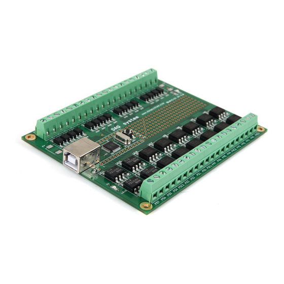
Page 9: Usb-Lt02_B Board Description
[Figure 3-1. USB-LT02 Layout] If you look at the picture above, in the case of USB-LT02, I/O functions are easy to use, and a simple circuit can be configured on a universal board by itself. A description of each is as follows. -
Page 10: Board Description
USB-LT02 User‟s Manual 3-2 Board Description Like the general 8051, it has program memory and data memory. Since the program memory area is programmed and supplied when the first board is provided as an OTP type, the user cannot reprogram it. -
Page 11: Usb2.0 B-Type Connector
When USB2.0 Port of PC and USB-LT02 are connected, USB Power(+5V) is supplied to USB-LT02 and this LED is turned on. 3-2-3 D2 LED Lights up when all input/output terminals of the USB-LT02 board are set as output. Used in sample programs.. 3-2-4 MICOM It is in charge of input/output control and USB data transmission with 16-Bit Micro- Controller. -
Page 12: U32
USB-LT02 User‟s Manual 3-2-5 SW1 Switch Press to reset the board. 3-2-6 Input Terminal [Figure 3-4. Input Terminal] The input terminal is a photo coupler, and the input voltage range is 12V ~ 24V. (For less than 12V, please contact us) It is designed so that there is no power polarity, and one common terminal is used per 4 input terminals. - Page 13 USB-LT02 User‟s Manual [Figure 3-5. Photo Coupler Input Circuit] For example, if GND is connected to P1C1 (common terminal) and the voltage level of the signal input to P70 is 12V, the input of USB-LT02_B is ON. (The polarity of the input voltage is irrelevant.)
-
Page 14: Output Terminal
USB-LT02 User‟s Manual 3-2-7 Output Terminal [Figure 3-6. Output Terminal] The output terminal uses a photo MOS relay, and the output control voltage range is P54, P55, P56, P57 and The maximum P5C2 terminal is 350V, and the continuous current that can flow is 130mA. - Page 15 USB-LT02 User‟s Manual The circuit between the common terminal and the output terminal is shown in [Figure 3-7]. [Figure 3-7. Photo MOS Relay Output Circuit] For example, MICOM gives a Logic Low signal (GND) to Port4.0 to make P4C1 and P40 conduct.
-
Page 16: In/Out Terminal Pin Map
USB-LT02 User‟s Manual 3-3 In/Out Terminal Pin Map For pin-out of Screw Terminal Connector for external input/output connection, refer to [Table 5] below. [Table 5. In Out Screw Terminal Connector Pin map] Name Description Remark P70, P71, P12, P13 Input Common... - Page 17 USB-LT02 User‟s Manual Photo MOS Relay Output Photo MOS Relay Output Photo MOS Relay Output P50, P51, P52, P53 Output Common P5C1 Terminal Maximum Output Control Range Photo MOS Relay Output : 60V/400mA Photo MOS Relay Output See paragraph 3-2-7.
-
Page 18: Sample Program
USB-LT02 User‟s Manual 4. Sample Program The CDROM provided with the board provides a sample program for use so that the board can be used easily. Since the USB HID device uses the driver of the operating system itself, there is no need to install a separate driver program. - Page 19 USB-LT02 User‟s Manual (1) Port Configure --- Set input and output mode of each port. Port : P5..P4 (Low Byte : P4) (Upper Byte : P5) Port : P1 P7 P6 (Low Byte: P6) (Upper Byte: P7 and P1) (2) Update --- Update the Port Configure value.
- Page 20 USB-LT02 User‟s Manual All Output --- All ports of MICOM are used as output. [Figure 4-4. All Output] However, the operation of the photo MOS relay is possible only for the corresponding pin. (Port 4, Port5) [Figure 4-5. Port 4 Output]...
- Page 21 All files specified above are included on the supplied CDROM. A sample program is provided with the USB-LT02 to facilitate the use of the USB-LT02. Since the USB HID Device uses the driver of the operating system itself, there is no need to install a separate driver program.
-
Page 22: Test
The test is executed using the “sample1.exe” program in the Exe folder of the CDROM on the PC where the USB-LT02 board is installed. The App and App0 folders of the CDROM contain the executable files and source files of sample1 and sample2, so the executable files are used for testing, and the provided sample source files can be modified and used by the user to implement the necessary functions. -
Page 23: Output Test
USB-LT02 User‟s Manual 5-2 Output Test (1) You can check the output function by turning on/off the LED on the board. [Figure 5-2. LED On/Off] In the picture above, you can see that the LED is on. It turns on when the output of bit 7 of port 6 is “0”, and turns off when it is “1”. -
Page 24: Appendix
USB-LT02 User‟s Manual Appendix A-1 Board Size The external dimensions of the board are as follows. For more detailed dimensions, please ask the person in charge. 115.6 107.9 P13 P1C1 P14 P17 P1C2 P63 P6C1 P64 P67 P6C2 34.3 USB-LT02... -
Page 25: Repair Regulations
(3) All DAQ SYSTEM products have a one-year warranty. -. The warranty period is counted from the date the product is shipped from DAQ SYSTEM. -. Peripherals and third-party products not manufactured by DAQ SYSTEM are covered by the manufacturer's warranty. - Page 26 -- Don Anderson, USB SIG(www.usb.org) 2. Universal Serial Bus Specification -- Compaq/Intel/Microsoft/NEC, MindShare Inc. (Addison Wesley) 3. USB-LT User‟s manual -- DAQ system 4. AN201 How to build application using APIs -- DAQ system 5. AN342 USB-LT02 API VER1.0 -- DAQ system...
- Page 27 USB-LT02 User‟s Manual MEMO Contact Point Web sit : https://www.daqsystem.com Email : postmaster@daqsystem.com...
Need help?
Do you have a question about the USB-LT02 and is the answer not in the manual?
Questions and answers