Table of Contents
Advertisement
Quick Links
USB3-FRM14
Windows, Windows2000, Windows NT and Windows XP are trademarks of Microsoft. We acknowledge that the
trademarks or service names of all other organizations mentioned in this document as their own property.
Information furnished by DAQ system is believed to be accurate and reliable. However, no responsibility is assumed by DAQ
system for its use, nor for any infringements of patents or other rights of third parties which may result from its use. No license is
granted by implication or otherwise under any patent or copyrights of DAQ system.
The information in this document is subject to change without notice and no part of this document may be copied or
reproduced without the prior written consent.
User's Manual
Copyrights 2005 DAQ system, All rights reserved.
1
-
-
USB3-FRM14 Users Manual (Rev 1.1)
http://www.daqsystem.com
Advertisement
Table of Contents

Related Manuals for DAQ system USB3-FRM14


Summary of Contents for DAQ system USB3-FRM14
- Page 1 Information furnished by DAQ system is believed to be accurate and reliable. However, no responsibility is assumed by DAQ system for its use, nor for any infringements of patents or other rights of third parties which may result from its use. No license is granted by implication or otherwise under any patent or copyrights of DAQ system.
-
Page 2: Table Of Contents
USB3-FRM14 Users Manual (Rev 1.1) -- Contents – 1. Introduction 2. USB3-FRM14 Function 2.1 Block Diagram 2.2 USB3-FRM14 Layout 2.3 Description of the functional Blocks 2.4 Connector Pin-out 2.4.1 CN1 Connecter 2.4.2 J1 Connecter 2.4.3 J2 Switch 2.4.4 J3, J8 BNC Connecter 2.4.5 J5 Jumper... -
Page 3: Introduction
1080p caution) 1. i : Interlaced 2. p : Progressive * USB3-FRM14 is supported up to 1080p(30fps), but Interlace mode does not currently support. The various serial digital interface standards all use coaxial cables with BNC connecters, with a nominal impedance of 75 ohms. The data of image, sound and various digital information (Line Counter, CRC) can carry hundreds meter far using coaxial cable. - Page 4 (usually PC). [Figure 1-1. USB3-FRM14 board Usage] As shown in Figure [1-1], the USB3-FRM14 is inserted into any available USB3.0 slot in your PC. It receives Image Frame through HD-SDI interface and saves the received data in the system main memory via Super Speed(5Gbps) USB3.0 interface.
- Page 5 USB3-FRM14 Users Manual (Rev 1.1) [Features of the USB3-FRM14] 1.485Gbit/s HD-SDI (High Definition Serial Digital Interface) Supports SMPTE 259M(SD-SDI), SMPTE344M(ED-SDI), SMPTE292M(HD-SDI) Supports 8-bit, 10-bit component digital video RGB or YCbCr 4:4:4 / YCbCr 4:2:2 or 4:2:0 ...
-
Page 6: Usb3-Frm14 Function
2. USB3-FRM14 Function 2.1 Block Diagram As shown in the following figure, main control of the USB3-FRM14 board is performed in FPGA Core Logic. Primary functions are receiving the image frame data through two Mini MDR-26 connector, and saving the DDR#1, DDR#2 memory, and transmitting to PC upon request. -
Page 7: Usb3-Frm14 Layout
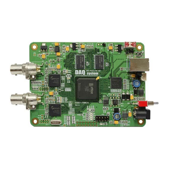
USB3-FRM14 Users Manual (Rev 1.1) 2.2 USB3-FRM14 Layout In this chapter, the primary functions of the USB3-FRM14 board are described briefly. For more information, refer to the device specification USB3-FRM14 Board REF1 REF2 123 789 123 789 www.daqsystem.com system USB3-FRM14 Rev. -
Page 8: Description Of The Functional Blocks
USB3-FRM14 Users Manual (Rev 1.1) 2.3 Description of the functional blocks (1) BNC Connecter : J3, J8 Caution) You should be used to connect the J8(Channel 0) connector at first. (2) SDI Receiver : U7, U14 Receive the SDI Data. -
Page 9: Connector Pin-Out
USB3-FRM14 Users Manual (Rev 1.1) 2.4 Connector Pin-out The board has several connectors and jumpers to set. The USB3-FRM14 board is equipped with two main connecters, USB3 B-type connector for USB connection and BNC connecter J3 and J8. 2.4.1 CN1 Connecter The USB3-FRM14 has a USB-B type connector for high speed USB connection. -
Page 10: J1 Connecter
U_SPI_MOSI Ground 2.4.3 J2 Switch USB3-FRM14 board is designed of four maximum USB3-FRM14 boards at the same time so as usable. Distribution of each board sets it up through 4 pin switch (J2) in a board. [Figure 2-5. J2 Switchj] [Table 5. -
Page 11: J3, J8 Bnc Connecter
USB3-FRM14 Users Manual (Rev 1.1) 2.4.4 J3, J8 BNC Connecter BNC(Bayonet Neil-Concelman) connecter is a miniature quick connect/disconnect RF connecter used for coaxial cable. It features three part of cable, at the center of the signal lines and coax internal signal that surround outer conductor (shield), and insulation. BNC connecters are made to match the characteristic impedance of cable at either 50 ohms or 75 ohms. -
Page 12: J10 Connecter
USB3-FRM14 Users Manual (Rev 1.1) 2.4.6 J10 Connecter The J9 connector is used for the FPGA program upgrade. Never use it at the normal operation. [Figure 3-6] shows the J9 connector. [Figure 2-9. J10 Connecter (Top View)] [Table 6. J10 Connecter Description]... -
Page 13: Ancillary Data
USB3-FRM14 Users Manual (Rev 1.1) 2.5 Ancillary Data USB3-FRM14 board can show Vertical Ancillary Data (VANC). Ancillary Data(commonly abbreviated as ANC Data), in the context of television system, refers to a means which by non-video information(such as audio, other forms of essence, and metadata). - Page 14 USB3-FRM14 Users Manual (Rev 1.1) All ANC packets must start with a specific start sequence, for component interfaces(the only kind of Srial Digital Interface is widespread use today), the start sequence is 0x00 0x3FF 0x3FF. This sequence is otherwise illegal in the serial digital interface. These words follow the start sequence in the header.
- Page 15 USB3-FRM14 Users Manual (Rev 1.1) (1) ADF --- Ancillary Data Flag always start sequence is 0x000, 0x3FF, 0x3FF (b9..b0 : in case of 10-bit) or 0x00, 0xFF, 0xFF(b7..b0 : in case of 8-bit). In the obsolete composite versions of SDI, the Ancillary Data start sequence is a single word, 0x3FCh.
- Page 16 USB3-FRM14 Users Manual (Rev 1.1) (2) SDID --- Secondary Data Identification word for Type 2 [Table 7. Data Identification Word Assignment] Data Data Data Assignment Data Data Data Type Value Type Value Assignment Undefined Format Undefined Format Type 2 01h ~ 03h...
- Page 17 USB3-FRM14 Users Manual (Rev 1.1) (5) DC --- Data Counter number word indicates how many user data words (UDW) to follow. The DC is an 8-bit value, encoded in the same fashion as the DID. (6) UDW --- User Defined Words are the “payload” present in the ANC packet, up to 255 bytes of user data is stored.
-
Page 18: Installation
The required PC operating system for the USB3-FRM14 is Windows XP SP1 higher or Windows 7. The USB3-FRM14 uses USB Super Speed interface thus “xxx USB 3.0 Root Hub” should be installed in your PC. You can check this condition by doing the following steps. - Page 19 USB3-FRM14 Users Manual (Rev 1.1) The item “USB 3.0 Root Hub” should be shown in the “Device Manager” window as shown in [Figure 4-1]. After checking the PC environmental conditions for USB3-FRM14, do the following steps to install the board (1) Install the USB3-FRM14 board into your system.
- Page 20 USB3-FRM14 Users Manual (Rev 1.1) [Figure 3-3. Specify the driver folder] Select “Search for the best driver in these locations”. Check “Search removable media (floppy, CD-ROM)”. Check “include this location in the search”. Click “Browse” button. Select the folder where the drivers are located. Click “OK”. Click “Next”.
- Page 21 USB3-FRM14 Users Manual (Rev 1.1) [Figure 3-4. Warning window] When you across a window’s warning message regarding to the compatibility problem as shown the [Figure 3-4] during the installation process, just click “Continue” button and go on the installation. If the installation is completely finished, a completion window message shall be shown as in [Figure 3-5].
- Page 22 USB3-FRM14 Users Manual (Rev 1.1) [Figure 3-5. “Completion” message window] http://www.daqsystem.com...
- Page 23 Grabber #11 Board” in the “Device Manager” window as shown in [Figure 3-6]. [Figure 3-6. “Device Manager” window] If you can see the “DAQ system USB3.0 Frame Grabber #11 Board” at the Universal Serial Bus controllers, the driver installation is to have been over. (Check the red circle)
-
Page 24: Sample Program
USB3-FRM14 Users Manual (Rev 1.1) 4. Sample Program DAQ system provides a sample program to make the user be familiar with the board operation and to make the program development easier. You can find the sample program in the CDROM accompanying with the board. -
Page 25: Image Processing
USB3-FRM14 Users Manual (Rev 1.1) DLL file (USB_FRM14.DLL) must be located in the same directory with the execution file or Windows system folder. Another method is to add the directory of API DLL file to PATH environmental variable. 4.1 Image Processing (Notice) The running order for the sample program as Check the Board # ... - Page 26 USB3-FRM14 Users Manual (Rev 1.1) Writing Method : Little Endian (In case of 10bit YUV) 26 25 16 15 10 9 One Frame Data size is as follow equation. case 0 (8bit): nSize = nXres * nYres case 1 (16bit):...
- Page 27 USB3-FRM14 Users Manual (Rev 1.1) [Figure 4-2. Image File Hex Value] (9) “Auto” toggle When check this box, it displays a video (10) “Skip” toggle When press this button, it displays a freeze-frame. (11) “Full screen” toggle It shows full screen.
-
Page 28: Anc Data Processing
USB3-FRM14 Users Manual (Rev 1.1) (12) “Half tone” toggle Select the Half tone mode filter. (13) “F/R” Frame Rates/sec 4.2 ANC Data Processing (Notice) Chapter 5 Test is more detailed description. (1) “Board #” Selection It selects a board number in case of the multi USB3.0 boards. It can select 0 ~ 4 at currently. -
Page 29: Image Saving
USB3-FRM14 Users Manual (Rev 1.1) (3) “Channel” Select the SDI channel. CH0 : Use the channel connected to J8 Connector. CH1 : Use the channel connected to J3 Connector. Dual : Two channels can be used simultaneously. (3) “Vanc Mode”... -
Page 30: Test
And, USB3-SDI01 is a simulator board for VANC data signal, it is changed SDI signal from the data of USB3-DIO01 and transmits the USB3-FRM14 board. Make sure that the VANC data is received correctly by connecting the USB3-DIO01 board USB3-SDI01 board as in [Figure 5-1]. - Page 31 USB3-FRM14 Users Manual (Rev 1.1) 5.1 Image Test First, the Frame Test program is shown in [Figure 5-2] after connect the camera to the J8 connector of USB3-FRM14 board. (Notice) The running order for the sample program as Check the Board # “Device Open” click “Device Init” click ...
- Page 32 USB3-FRM14 Users Manual (Rev 1.1) Under [Figure 5-3] is an example of the display when you select the "Half tone" for image improvement. [Figure 5-3. “CH 0” Improvement Display] http://www.daqsystem.com...
- Page 33 USB3-FRM14 Users Manual (Rev 1.1) [Figure 5-4] is the screen when you select the "Full Scree". Select the Full Screen, and a larger window, it is possible to see the resolution entire selected. Sometimes Frame Rate varies according to the system specifications.
- Page 34 USB3-FRM14 Users Manual (Rev 1.1) Under [Figure 5-5] is the screen when you have selected two channels simultaneously. Frame Rate according to the system requirements may change. [Figure 5-5. When two channel select (Windows XP 32bit)] (Notice) When sometimes the application program downs and there is only one video on the screen, we recommend that you use to connect the connector external power(12V DC) to J9 connector.
- Page 35 USB3-FRM14 Users Manual (Rev 1.1) The [Figure 5-6] is the display when using the two channels on Windows 7 64bit O.S. F/R(Frame Rate) represents the 61 frame, it can be seen in each channel video from SDI two cameras for each 30 frames.
- Page 36 USB3-FRM14 Users Manual (Rev 1.1) [Figure 5-7. When using the two channel (Windows 7 64-bit), Using half tone] When comparing [Figure 5-5] and [Figure 5-7], the Frame Rate may change according to the system requirements. So, the test on Windows 7 is better testing on Windows XP. And, 64bit O.S is better than 32-bit O.S.
-
Page 37: Board Connection
USB3-FRM14 Users Manual (Rev 1.1) 5.2 VANC Test The board connection for VANC implementing is as [Figure 5-8]. USB3-DIO01 USB3.0 USB3-FRM14 Interface USB3.0 Data Interface VANC Data USB3-SDI01 Board Connection [Figure 5-8. Board Connection] First, an application program of USB3-DIO01 when used is as [Figure 5-9]. - Page 38 USB3-FRM14 Users Manual (Rev 1.1) [Figure 5-9. VANC Data Transmit Program] That command description is as follows. Device Open --- Open the device. It is performed only once in the beginning. Device Init --- Current device that attached to the system is initialized.
- Page 39 [Figure 5-10] is a screen of Frame Test program, shows that VANC data is received on channel 0 of USB3-FRM14. You can see that the values of VANC CH0 data on the top left column (Check the inside red circle) when “Vanc Out” press in [Figure 5-9].
- Page 40 USB3-FRM14 Users Manual (Rev 1.1) The first and second VANC data is only displayed in [Figure 5-10]. If necessary, user can be used 4 VANC data packet by user defined. ANC data packet is 512 bytes including the part of Header and other packet information and user data’s (UDW) 255bytes.
-
Page 41: Appendix
USB3-FRM14 Users Manual (Rev 1.1) Appendix A.1 Specification USB3.0 Interface USB 3.0 Interface Super Speed Device 5Gbps Physical Characteristics Camera Interface : Dual HD-SDI Dimension : 109 x 79.5 mm Power Requirement Voltage : +3.3V (Max. 500mA) +12V (Max. -
Page 42: Physical Dimension
USB3-FRM14 Users Manual (Rev 1.1) A.2 Physical Dimension The approximate external dimensions of the board are as follows. For more detailed measurements, ask the person in charge. http://www.daqsystem.com... - Page 43 USB3-FRM14 Users Manual (Rev 1.1) References 1. USB 3.0 System Architecture -- Don Anderson, USB SIG(www.usb.org) 2. Universal Serial Bus Specification -- Compaq/Intel/Microsoft/NEC, MindShare Inc. (Addison Wesley) 3. AN201 How to build application using API -- DAQ system 4. AN342 USB3-FRM14 API ver1.0 -- DAQ system http://www.daqsystem.com...
Need help?
Do you have a question about the USB3-FRM14 and is the answer not in the manual?
Questions and answers