Table of Contents
Advertisement
Quick Links
Advertisement
Table of Contents

Related Manuals for Metrix ScopiX IV


Summary of Contents for Metrix ScopiX IV
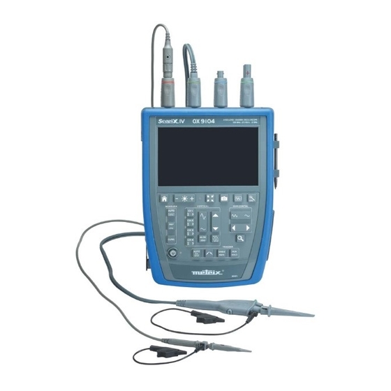
- Page 1 GB - User’s manual ScopiX IV OX 9062 OX 9102 OX 9104 OX 9304 OX9302-BUS DIGITAL OSCILLOSCOPES - 60MHz, 2 isolated channels - 100MHz, 2 isolated channels - 100MHz, 4 isolated channels - 300MHz, 4 isolated channels - 300MHz, 2 isolated channels...
- Page 2 Thank you for purchasing a ScopiX IV digital oscilloscope with isolated channels. For best results from your device: Read this user manual attentively, Observe the precautions for its use. WARNING, risk of DANGER! The operator must In the European Union, this product is subject to...
-
Page 3: Table Of Contents
CONTENTS 1. GENERAL..............5 4.6.1. Active keys in the BUS Analysis mode ....46 4.6.2. Active keys of the keypad: ......... 46 1.1. Introduction ............5 4.6.3 Screen icons of the bus analysis mode ..... 47 1.2. Delivery condition ..........5 4.7. - Page 4 12. APPENDIX ............111 12.1 « ARINC 429 » Bus ........111 12.1.1. Overview ............111 12.1.2. Getting started ..........111 12.1.3. Measurements (ARINC 429) ......112 12.2 « AS-I » Bus........... 113 12.2.1. Overview ............113 12.2.2. Getting started ..........113 12.2.3.
-
Page 5: General
BAN Probix adapter 1/10 500MHz probe, 300V HX0130 4 (300MHz) CAT III 1/10 250MHz probe 600V HX0030C 4 (100MHz) CAT III HX0120 METRIX carrying case HX0121 Stylus HX0122 Carrying strap P01296051 LI-ION 6.9 Ah battery pack P01102155 PA40W-2 mains adapter P01295174... -
Page 6: Accessories
General 1.3. Accessories 1.3.1. Measurement accessories (current, voltage, temperature) Terminations Mini Amp SK1-19 Banana SP10-13 Probe Clamp FLEX FLEX sensors sensors adapter adapter clip SK1-20 300V HX0130 CAT III Voltage 500MHz 600V HX0030C CAT III Voltage 250MHz 300V ... -
Page 7: Other Accessories
General 1.3.2. Other accessories Specifications Accessories for Probix Probix Adapater Banana adapter HX0064 HX0033 Industrial accessories kit HX0071 HX0030B µSD HC memory card HX0179 8GB + SD USB-µSD adapter HX0080 Demonstration test circuit HX0074 BNC M-F4 Adapter HX0106 HX0031 Ext. Li-Ion charger P01102130 45 AAC MA200... -
Page 8: Lithium-Ion Technology
General Replacing The battery of this instrument is specific: it includes suitable protection and safety elements. the battery Replacement of the battery by a model other than the one specified may cause material damage and bodily injury by explosion or fire. Replacement 1. -
Page 9: Isolation Of The Channels
General 1.5. Isolation of the channels ScopiX has 2 or 4 channels that are isolated not only with respect to each other but also with respect to earth (600V CAT III): Diagram of the electronic structure of the ScopiX : ... -
Page 10: Probix Accessories
General 1.6. Probix accessories 1.6.1. Probix concept ScopiX uses Probix intelligent probes and sensors, which are recognized automatically when connected, giving the user active safety. At the time of connection to an input of the oscilloscope, a safety message (in English) concerning the probe or sensor used indicates: ... -
Page 11: Auto Scale
General 1.6.3. Auto scale Some Probix probes have buttons, the assignments of which can be programmed: A The HX0030 probe has three directly accessible control buttons: Button A (programmable): modification of the settings of the channel to which it is connected ... -
Page 12: Description Of The Instrument
Description 2. DESCRIPTION OF THE INSTRUMENT 2.1. Front panel Hard enclosure covered with Probix terminal elastomer, tight to drops of water block falling vertically, IP54 Colour screen Display of the applied signals, accompanied by all adjustment parameters. The screen is divided into The main command functional zones: display of the functions can be modified by the... -
Page 13: Touch Screen And Stylus
Description 2.3. Touch screen and stylus Display Colour screen: LCD WVGA (800x480) 7 inch resistive, colour, touch operated (can be used with protective gloves) Backlighting by LEDs Brightness adjustable by the key on the keypad and Lux sensor: automatically adjusts the brightness to suit the environment of use... -
Page 14: Accessories
Description 2.4. Accessories HX0122 strap with self- Attaching the strap (length adjustable from 42 to 60cm) to the instrument: sticking tape, CLIC ! CLIC ! Fitting the strap: to carry in your hand or on your shoulder Removing the strap: CLIC ! Stand providing an angle of 40°... - Page 15 Description HX0120 The carrying/protection case includes: carrying 1 waterproof all-terrain bottom case 2 handles 1 shoulder strap 1 removable interior compartment with 3 stowage areas: - 1 central compartment with a plasticized pouch for the ScopiX, - 2 side pockets with 2 modulable self-adhesive separators for stowing the accessories.
-
Page 16: Communication Interfaces
Description 2.5. Communication interfaces Communication interfaces These are grouped in a specialized space on the right side of the oscilloscope and protected by a plug that must be lifted off to reach them. USB connector RJ45 Ethernet MicroSD Probe (USB connector card calibration... -
Page 17: Getting Started
Getting started 3. GETTING STARTED 3.1 General principles The dialogue boxes are displayed at the bottom of the screen. They do not overlap the space set aside for the curves, and so leave an unobstructed view of the user's action on the channel. Only the adjustments that concern this curve remain displayed. -
Page 18: Home" Key And Icon
Getting started 3.5 "HOME" key and icon If Then (on the screen) you press the you return to the home screen from your "HOME" key measurement session of the keypad you directly access the instrument's various operating modes: ... -
Page 19: Functional Description Of Ox 9304
Functional Description 4. FUNCTIONAL DESCRIPTION OF OX 9304 4.1 SCOPE mode Reference Screen shot 4.1.1 Keys/ active keypad Brightness Full screen Autoset memory "Home" Automatic measurements Horizontal time base Reference of the measurements Zoom Vertical Cursors adjustments Triggering ON/OFF key 4.1.2 Adjustment of the "Reference Memory"... -
Page 20: Display Of The Measurement Principles ("Measure") From The Keypad
Functional Description 4.1.4 Display of the measurement principles ("MEASURE") from the keypad Activates or deactivates display of the window of the 20 automatic measurements of the reference trace. Activates the 20 automatic measurements of the 4 traces with displacement by "scrolling". - Page 21 Functional Description b) from the screen Click at top right in the screen, on the Time Base zone (see opposite). Description below of the Y(t) - Y(f) - XY display modes 1. Y(t): temporal view of a waveform Settings from 1ns to 200s No averaging Selection of a coefficient in order to calculate an average on the samples displayed: this can be used for example to attenuate the...
- Page 22 Functional Description Use this mode to display extreme values of the signal, acquired between two samples of the acquisition memory. This mode is used: to detect a false representation due to undersampling to display events having a short duration (Glitch, ≤2ns). Whatever time base is used, with its corresponding sampling rate, events having a short duration (Glitch, ≤2ns) are displayed.
- Page 23 Functional Description Rectangle Hamming Hanning Blackman Flat top Before calculating the FFT, the oscilloscope weights the signal to be analyzed by a window that acts as a bandpass filter. The choice of type of window is essential to distinguish the different spikes of a signal and make accurate measurements.
- Page 24 Functional Description Horizontal unit: This is indicated in place of the time base and is calculated from the sweep coefficient: Sweep coefficient 12.5 Unit in ( Vertical unit: The sub-menus propose two possibilities: unit of the signal in its time-domain representation (V/div) a) Linear scale: by selecting the FFT menu, then linear scale in (V/div)= b) Log scale: by selecting the FFT menu, then log (logarithmic) scale...
-
Page 25: Adjustment Of The Amplitude Of The "Vertical" Signal
Functional Description 4.1.6 Adjustment of the amplitude of the "VERTICAL" signal a) from the keypad Selection of the channel Activation of the channel De-activation of the channel Adjustment of the vertical sensitivity of the last channel selected: ... - Page 26 Functional Description b) from the screen defines the vertical scale of the channel selected from the current settings. This yields a reading of the direct measurements of the quantity Example: analyzed and of its unit. AC Coupling: DC GND ...
-
Page 27: Trigger
Functional Description 4.1.7. Adjustment of the triggering level, "TRIGGER", a) from the keypad Adjustment of the triggering level on the mean value of the signal (50%) without modifying the coupling of the trigger. A press combined with a CHx key starts the same function, but first selects the corresponding channel as triggering source Selection, by successive presses, of the triggering slope (positive or negative). -
Page 28: Adjustment Of The Triggering Level
Functional Description b) from the screen 1. Edge Selection of a channel as triggering source E.g. CH4 Triggering source Selection of the filter of the main triggering source: AC coupling (10Hz to 300MHz): blocks the DC component of the signal. DC coupling (0 to 300MHz): passes the whole signal. - Page 29 Functional Description Selection of triggering on pulse width: 2. Pulse The edge is selected either in the "Trigger" tab or from the keypad and defines the limits of the analysis: edge defines a pulse between edge defines a pulse between In all cases, the actual triggering is on the end-of-pulse edge: t>T1 triggers on a pulse, if its duration is greater than setpoint T1...
- Page 30 Functional Description Triggering Selection of the desired delay: delay Pointing to this field opens on the screen a virtual digital keypad for direct entry of the value Trigger Selection of triggering on edges with delay: Adjustments on the triggering source The delay is triggered by the auxiliary source.
- Page 31 Functional Description 4.Counting Selection of triggering on edge with counting of events. Qualifier Selection of adjustments on the qualification source: 100 µs Disabling of triggering for a preset duration and, among other things, stabilization of triggering on pulse trains. Pointing to this field opens on the screen a virtual digital keypad for direct entry of the value.
-
Page 32: Mathematical Function, From The Screen
Functional Description 4.1.8. MATHEMATICAL function, from the screen Definition, for each trace, of a mathematical function and of the vertical scale Equation editor (functions, in the channels or simulated, programmable as F1, F2, F3, F4): Addition Subtraction Multiplication ... -
Page 33: Automatic Measurements, From The Screen
Functional Description 4.1.9. AUTOMATIC measurements, from the screen Opening of the "Automatic measurements" Menu window of the channel Opening of the "Automatic measurements" Menu window of the 4 channels The measurements are made and refreshed on the selected reference trace. All measurements that can be made on this trace are displayed. -
Page 34: Backup
Functional Description Presentation T = 1/F of the automatic measurements Vmax 100% Vhigh >5%T Vavg Vamp Vpp Vlow Vmin Tfall Trise >5%T • Positive overshoot = [100 * (Vmax – Vhigh)]/Vamp • Negative overshoot = [100 * (Vmin – Vlow)]/Vamp ∑... -
Page 35: Multimeter Mode
Functional Description 4.2 Multimeter mode 4.2.1 Keys/keyboard active in Multimeter mode The ScopiX has a "Multimeter" function with 8000 display points. It has as many independent multimeters as there are channels in the "Oscilloscope" mode (2 or 4), with the same function as in the Oscilloscope mode: Probix. Coupling: If a channel is activated and selected, pressing this key changes the input coupling of the channel. -
Page 36: Icon/Screen Of The Multimeter Mode
Functional Description 4.2.2 Icon/screen of the Multimeter mode The channel is displayed in the colour defined in the "Oscilloscope" mode. The inactive channels are displayed in white. Display of the screen: 4 measurements 4 channels Several types of measurement are possible on CH1; the other channels are voltmeter channels only. -
Page 37: Adjustments Of The Vertical Menu
Functional Description 3 secondary If no display is selected, or if no display is possible (e.g. frequency measurement of a DC measurements signal, etc.), the string '-----' is displayed. that can be selected by the If the channel is not selected, the string '-X-' is displayed. If the signal is outside of the range: icons "OL"... -
Page 38: Power Measurement
Functional Description 4.2.4. Power measurement Display The following secondary measurements: MIN/MAX relative frequency are available in this quantity. Choice of set-up with type of power and direct display of the 4 power parameters Single-phase ���� ∗ � ����(����) ∗ ����(����) ����... - Page 39 Functional Description Exit from the Power mode by selection of the icons opposite. Backup of the configuration...
-
Page 40: Logger Mode
Functional Description 4.3 LOGGER mode 4.3.1 Keys/keyboard active in LOGGER mode Upon entry into the LOGGER mode, a file is automatically generated. This file records 10,000 measurements in all active channels: duration of the record 20,000s, resolution 0.2s. 4.3.2 Icons/screen in LOGGER mode The LOGGER mode records the measurements of the multimeter mode. -
Page 41: Principles
Functional Description 4.3.3 Principles Automatic (N files of 100,000 measurements) in the memory of the LOGGER directory. sequential recording Leave enough space for the recording. In the even of a power outage, the oscilloscope is self-contained thanks to its battery and the files being recorded are kept in memory. -
Page 42: Viewer Mode
Functional Description - Viewer 4.4 VIEWER mode File manager Look-up of files in internal memory and on SD Card creates a new directory. erases a directory or a file after confirmation. duplicates a file. renames a file from the alphanumeric keypad. displays an analysis file, which opens in the mode recorded, except for .png screen shot files, which are opened in a specific viewer with file processing tools: erasure, printing, displacement of windows. - Page 43 Functional Description - Viewer VIEWER Recall of a .rec "VIEWER" file appears in the screen background and the LOGGER mode is identified by the icon at bottom right of the screen; see opposite. Arrows for browsing from one file to another in the same directory Recall of a .png file A window (which can be moved by cursor) appears at the top of the screen:...
-
Page 44: Harmonic Mode
Functional Description 4.5 HARMONIC mode 4.5.1. Keys/keyboard active in Harmonic mode 4.5.2. Principle The Harmonic mode is used to display the breakdown into harmonics of a voltage or a current of which the signal is steady-state or quasi-steady-state. It establishes a first diagnostic of the harmonic pollution of an installation. -
Page 45: Icons/Screen In Harmonic Mode
Functional Description 4.5.3. Icons/screen in Harmonic mode Display of the result of the harmonic analysis of the selected traces. The harmonic analysis of traces ch1 and ch4 is represented in the form of solid-colour bar charts (in the colour of the trace). As default, the fundamental is selected automatically, but the fundamental frequencies of 50Hz/60Hz and 400Hz... -
Page 46: Bus Analysis Mode
Functional Description 4.6 BUS Analysis Mode 4.6.1. Active keys in the BUS Analysis mode 4.6.2. Active keys of the keypad: HOME LUMINOSITE SCREENSHOT ON/OFF/VEILLE In the bus analysis mode, the "vertical", "horizontal", "measurement", and "trigger" menus are not available. -
Page 47: Screen Icons Of The Bus Analysis Mode
Selection of the configuration and display of the connections necessary for the analysis of the selected bus. SCOPIX IV proposes a set of bus configurations and connection diagrams. These files cannot be deleted or modified, but can be copied and then modified. The .bus* file extension identifies configurations that have been modified by the user. - Page 48 Functional Description Analysis Start of analysis of the selected bus, in steps. Results of the analysis Display of the results of the last analysis performed. If the measurement lies within the specified interval, it is displayed in green. If the measurement lies within the interval of acceptability, it is displayed in yellow. If the measurement is outside both of these intervals, it is displayed in red.
-
Page 49: Communication
Functional Description 4.7. Communication The communication interfaces are grouped in a specialized space on the side of the ScopiX , protected by a cover. You can communicate on several interfaces: USB type B for communication with a PC The cord supplied is used to connect to the USB type A port of a PC: transfer of file, programming using SCPI commands ... -
Page 50: General Parameters
Functional Description 4.7.1 General parameters Can be accessed from the home screen by Update of the date (day, month, year) and time (hour, minute, second). The selection is made by the stylus, using the scroll bars on either side of the parameters to be adjusted. Date/Time The clock starts when the menu is closed. - Page 51 Functional Description IP address An IP address is coded in 4 bytes, displayed in decimal form 132.147.250.10 Each field can be coded between 0 and 255; the fields are separated by decimal points. Unlike the physical address, the IP address can be modified manually by the user or automatically by DHCP.
-
Page 52: Memories
Functional Description 4.8. Memories Backup The files are stored in a specific partition. memories File system: 1. on an SD Card; the partitions of the SD Card are accessible in the sdcard_pX directory, 2. in the local file system. Available memory size Internal memory of the instrument: 1GB for the file system ... -
Page 53: Update Of The Firmware Of Embedded Programs
Functional Description 4.9 Update of the firmware of embedded programs Firmware Periodically, an "update available" message may appear on the home screen, if the ScopiX is connected to Ethernet or WiFi: This message means that update files have been downloaded transparently to the ScopiX : they are available for an update, which is recommended in order to obtain new functions, bug fixes;... -
Page 54: Scopenet Iv
The PC environment uses icons in an HMI identical to the Scopix IV product, with the same access to the functions and adjustments. In "Oscilloscope" mode, ScopeNet IV proposes adjustments by a right click on the waveform: RUN/STOP, AUTO/TRIG/SINGLE/AUTOSET and ZOOM are easy-to-configure parameters. - Page 55 Applications Backup in the various modes (Oscilloscope, Multimeter, Logger, Harmonic) is possible from the PC, configuration files: "adjustments" for all modes "harmonics" "traces and math" for the oscilloscope mode. The backup is recorded in the file system of ScopiX (internal or SD Card).
-
Page 56: How Are Waveforms Displayed
Applications 5. HOW ARE WAVEFORMS DISPLAYED? 5.1 "Manual" display To view the signal and project it on the screen, you must know (or imagine), as prerequisites, the following characteristics: the coupling whether the signal is pure AC or has a DC component, ... -
Page 57: Using The Touch Screen
Applications 5.1.2. Using the touch screen Icon Action Connect the Probix probe to the input of the channel. Click the channel to refresh it ("channel activated") and access parameterizing. Press the type of coupling to select the desired coupling. -
Page 58: Calibrating The Probes
Applications 5.3 Calibrating the probes Step Action Connect the Probix adapter of an HX0030 probe having a 1/10 ratio to the CH1 input. Connect the probe (with its ground) to the calibrator output (Probe Adjust: ≈3V, ≈1kHz) on the side of the instrument. - Page 59 Applications Compensation of Act on the screw on the Probix HX0030 probe to adjust the compensation. the HX0030 probe For an optimum response, adjust the low-frequency compensation of the probe so that the plateau of the signal is horizontal. Probe overcompensated Probe correctly compensated Probe under-compensated...
-
Page 60: Auto/Cursors/Zoom Measurement
Applications 5.4 Auto/Cursors/Zoom measurement 5.4.1. Auto For optimum measurement accuracy, we recommend displaying two complete periods of one or more signals. To do this, modify the time base in a logical way using the "horizontal" keys. There are two ways to start Auto measurements in a channel: ... -
Page 61: The Cursors
Applications List of the different Time measurements Level measurements values in rise time DC voltage Auto measurements fall time RMS voltage positive pulse peak-to-peak voltage negative pulse amplitude duty cycle max. voltage period min. voltage frequency upper plateau phase lower plateau counting overshoot integral... -
Page 62: Adjusting The Trigger
Applications 5.5 Adjusting the Trigger Choose the triggering mode that corresponds to your application. Set the values of all triggering parameters. Example: Triggering on edge Exit from the window by clicking the cross. -
Page 63: Mathematical/Fft/Xy Measurement
Applications 5.6 Mathematical/FFT/XY measurement Mathematical functions These serve to process your readings as a function of the parameterizings you implement on one of the channels of the instrument. These functions can be accessed using the key on the screen to specify the channel you want. -
Page 64: How Is A Quantity Measured By Multimeter
Applications 6. HOW IS A QUANTITY MEASURED BY MULTIMETER? 6.1 Differentiating the channels Channel 1 of the ScopiX is named CH1. It is used to measure various physical quantities in addition to the signal amplitude measurements, using the appropriate Probix accessories. -
Page 65: Power Measurement
Applications Remarks The channels of the measurement ranges are automatic. To define the measurement range in manual mode, press the key opposite. A long press on the key of the channel is used to return to automatic mode. In addition: ... -
Page 66: Logger Mode
Applications 6.4 LOGGER mode This utility of the Multimeter mode is used to record the values read on the various channels of the ScopiX , whatever the type of measurement. The records may be long. It is therefore preferable to connect ScopiX to line power so as to avoid a sudden stoppage of the measurement when the battery is depleted. -
Page 67: How Are Harmonics Analyzed
Applications 7. HOW ARE HARMONICS ANALYZED ? It is possible to go from harmonic to harmonic using the keys. These numerical characteristics are obtained: value in % of the harmonic of greatest amplitude phase in ° with respect to the fundamental ... -
Page 68: Technical Characteristics
Technical characteristics 8. TECHNICAL CHARACTERISTICS 8.1. "Oscilloscope" function Only the assigned tolerance or limit values are guaranteed values (after a half-hour warm-up period). The values without tolerances are given as an indication Vertical deflection OX 9102 Characteristics OX 9062 OX 9304 OX 9104 Number of channels OX 9xx2: 2, OX 9xx4: 4... - Page 69 Technical characteristics Horizontal deflection (time base) Characteristics OX 9062 - OX 9102 - OX 9104 - OX 9304 Time base ranges 35 ranges, from 1ns to 200s/div. Accuracy of the time base ±[0.0005% + max (500ps, 1 sample)] 2.5GS/sec. in real time Sampling frequency 100GS/sec.
- Page 70 Technical characteristics Triggering circuit OX 9102 Characteristics OX 9062 OX 9304 OX 9104 CH1, CH2, CH3, CH4 (OX 9xx4) CH1, CH4 Triggering sources CH1, CH4 (OX 9102) Automatic Triggered Triggering mode Single-shot Auto Level 50% ≥10Hz 10Hz to 100MHz 10Hz to 200MHz BW on triggering 0Hz to 100MHz 0Hz to 200MHz...
- Page 71 Technical characteristics Acquisition system Characteristics OX 9062 - OX 9102 - OX 9104 - OX 9304 Resolution of the ADC 12 bits 2.5GS/s in real time Maximum sampling frequency 100GS/s with repetitive signal (ETS) according to time base 1 converter per channel Minimum width of Glitches that can be detected: ≥...
- Page 72 Technical characteristics Processing of measurements Mathematical functions Equation editor (functions on the channels or simulated functions): Addition, subtraction, multiplication, division, and complex functions between channels. Automatic measurements Time measurements Level measurements rise time DC voltage fall time RMS voltage positive pulse peak-to-peak voltage negative pulse amplitude...
- Page 73 Technical characteristics Display Characteristics OX 9062 - OX 9102 - OX 9104 - OX 9304 Display screen LCD 7’’ TFT (colour display) Backlighting by LEDs Brightness Continuous adjustment Resolution WVGA, or 800 pixels horizontally x 480 pixels vertically Screen saver Choice of delays: 15', 30', 1h, or none Display without Zoom Complete memory: 100,000...
-
Page 74: Multimeter" And "Logger" Function
Technical characteristics 8.2 "Multimeter" and "LOGGER" function Only the assigned tolerance or limit values are guaranteed values (after a half-hour warm-up period). The values without tolerances are given as an indication. Display 8,000 points as voltmeter Input impedance 1MΩ Max. input voltage 600 Vrms sine and 800 VDC without probe 1000 Vrms and 1400 VDC with HX0030 probe DC measurement... - Page 75 Technical characteristics Resistance measurement In Channel 1 Ranges (full scale) Ohmmeter Resolution Measurement current 80Ω 0.01Ω 500µA 800Ω 0,1Ω 50µA 8kΩ 1Ω 50µA 80kΩ 10Ω 2µA 800kΩ 100Ω 2µA 8MΩ 1000Ω 50nA 32MΩ 10kΩ 50nA Accuracy ±(0.5% + 25 D) from 10% to 100% of the scale ≈3V Open-circuit voltage Continuity measurement...
-
Page 76: Operating Modes
Technical characteristics Operating modes Relative mode Display with respect to a base measurement Surveillance (statistical) on all measurements The Relative, Surveillance, and Frequency in MAX MIN value modes are mutually exclusive. Frequency The frequency can be displayed in AC mode Interval of time between 0.2s 2 measurements... -
Page 77: Viewer" Function
Technical characteristics 8.3 "VIEWER" function The "VIEWER" function is used to read a file acquired in "LOGGER" mode. Horizontal zoom Zoom coefficient: x1 to x100 The oscilloscope has a memory capacity of 100,000 pts per channel. Vertical zoom ZOOM factors: maximum 16 ±... -
Page 78: Harmonic Analysis" Function
Technical characteristics 8.4 "HARMONIC ANALYSIS" function Presentation of the harmonics in bargraph form Crosshair with vertical axis graduated in % Horizontal axis graduated in orders of harmonic Display of 63 orders The harmonic analysis function can be implemented on the 4 channels ... -
Page 79: Communication
USB Electrically isolated CDC (Communication Device Class) ACM (Abstract Control Model) protocol to submit SCPI queries MS (Mass Storage) protocol to manipulate the file system of SCOPIX IV (and its SDCARD). RNDIS (Remote Network Driver Interface Specification) to communicate via... -
Page 80: General Characteristics
General Characteristics 9. GENERAL CHARACTERISTICS 9.1. Nominal range of use 9.1.1. Environmental conditions Reference temperature + 18°C to + 28°C Temperature of use °C to + 40°C Temperature of storage - 20°C to + 70°C <80% RH + 35°C; <70% from 35°C to 40°C Relative humidity (limited to 70% in the 8MΩ... -
Page 81: Mechanical Characteristics
General Characteristics 9.2. Mechanical characteristics 9.2.1. Hard enclosure covered with elastomer Comprising - a lower housing, - a central belt holding all terminations, - an upper housing, - a battery compartment cover. Dimensions: 292.5x210.6x66.2mm Weight: approximately 2.4 kg with the battery ... -
Page 82: Electrical Characteristics
General Characteristics 9.3. Electrical characteristics 9.3.1. Battery power supply Li-Ion technology Nominal voltage: 10.8V Operating voltage: 10V to 12V Capacity: 5800mAh/62 Wh (model 695065A00) 6900mAh/74 Wh (model 695066A00) Battery protected from short circuits by resettable fuse ... -
Page 83: Cem And Safety
General Characteristics 9.4. CEM and safety 9.4.1. Electromagnetic compatibility The products are compliant with the standards and any respective amendments, in their industrial classification: IEC 61326-1 with a quantity of influence in the presence of a magnetic field of 10V/m 9.4.2. -
Page 84: Temperature
General Characteristics Derating values a) Electrical safety: Max. voltage between references, and between reference and ground, vs frequency 1000 Vrms 600 Vrms 100 Vrms 10 Vrms 5 Vrms 1 Vrms 0,01 MHz 0,1 MHz 1 MHz 10 MHz 100 MHz Frequency b) Input voltage: Max. -
Page 85: Maintenance
Maintenance MAINTENANCE 10.1. Warranty This oscilloscope is guaranteed for three 3 years against defects of materials or workmanship, in accordance with the general terms of sale. During this period, the instrument must be repaired only by the manufacturer, which reserves the right either to repair the instrument or to replace all or part of it. If the equipment is sent back to the manufacturer, the customer pays for shipping to the manufacturer. -
Page 86: Remote Programming
Remote Programing REMOTE PROGRAMMING 11.1. Introduction Programming convention Tree concept The SCPI commands have a branching structure. A command must end with a terminator, <NL> or <;>. If commands are separated by the character <;> and are located in the same directory, there is no need to repeat the whole tree. - Page 87 Remote Programing Format of the parameters The parameters can be key words, digital values, character strings, or digital expressions. The interpreter is case-insensitive. Key words The key words can take two forms, like the instructions: the abbreviated form (in upper-case) The complete form (abbreviated form plus lower-case complement).
- Page 88 Remote Programing Special values MAXimum, MINimum are used to obtain the extreme values of the parameter. UP, DOWN are used to go to the value following or preceding the current state of the parameter. Character strings These are series of letters and/or digits enclosed in quotation marks " ". Terminator <NL>...
-
Page 89: Commands Specific To The Instrument
Remote Programing 11.2. Commands specific to the instrument ABORt (Command) The ABOR command aborts the acquisition in progress. If the instrument is set in the single mode, the acquisition is stopped. The instrument stays in the starting status. If the instrument is in continuous mode, the acquisition in progress is stopped and the following starts. - Page 90 Remote Programing ARM[:SEQuence{[3]|4}] (Command/Query) :SOURce The ARM:SOUR <INTernal{1|2|3|4}> command determines the auxiliary trigger source of the instrument. INTernal{1|2|3|4} corresponds to the trigger source (1, 2, 3, 4 channels) of the instrument on SCOPIX and SCOPIX BUS. To the question ARM:SOUR?, the instrument returns the used trigger auxiliary source. AUTOSet:EXEcute (Command) The AUTOS:EXE command starts an autoset on each active channel.
- Page 91 Remote Programing DISPlay[:WINDow]:CURSor (Command/Query) :STATe The DISP:CURS:STAT <1|0|ON|OFF> command activates or inhibits the manual measurements. 1|ON: activates the manual measurements 0|OFF: inhibits the manual measurements To the question DISP:CURS:STAT?, the instrument returns the activation status of the manual measurements.
- Page 92 Remote Programing DISPlay[:WINDow]:TRACe (Command/Query) :XY:XDEFine The DISP:TRAC:XY:XDEF <INT{1|2|3|4}> command selects the signal positioned on the X-basis. To the question DISP:TRAC:XY:XDEF?, the instrument returns the signal used on the X-basis. DISPlay[:WINDow]:TRACe (Command/Query) :XY:YDEFine The DISP:TRAC:XY:YDEF <INT{1|2|3|4}> command selects the signal positioned on the Y-basis.
- Page 93 Remote Programing FORMat[:DATA] (Command/Query) The FORM <INTeger|ASCii|HEXadecimal|BINary> command selects the data format of the trace transfer. INTeger: The data transmitted consists in whole numbers, unsigned with a length of 32 bits, preceded by the heading #an. n represents the number of data items to transmit. a gives the number of figures making up n.
- Page 94 Remote Programing INITiate:CONTinuous:NAME (Command) INIT:CONT:NAME <EDGE|PULse|DELay|EVENt>,<1|0|ON|OFF> starts or stops the acquisition in repetitive mode in the indicated trigger mode. In the CAPTure mode, the capture of faults in (Recorder) files is used. INITiate[:IMMediate]:NAME (Command) INIT:NAME <EDGE|PULse|DELay|EVENt> runs an acquisition in single mode. INPut{[1]|2|3|4}:COUPling (Command/Query) The INP{[1]|2|3|4}:COUP <AC|DC|GROund>...
- Page 95 Remote Programing MEASure:DMM? (Query) To the question MEAS:DMM? <INT1|2|3|4> the instrument returns the value of the main measurement for the selected channel. INT1 to INT4 index are associated with channels 1 to 4. Use the index to find INT5 power measurement.
- Page 96 Remote Programing MEASure:NWIDth? (Query) To the question MEAS:NWID? <INT{1|2|3|4}> the instrument returns the negatitive pulse width of the selected signal. Response format: <measured value><NL> value in format <NR3> expressed in second. (Query) MEASure:PDUTycycle? To the question MEAS:PDUT? <INT{1|2|3|4}> the instrument returns the duty cycle of the selected signal.
- Page 97 Remote Programing MMEMory:CATalog? (Query) To the question MMEM:CAT? [<LOCAL|SDCARD>] the device returns the list of files present in the local memory. If the file system is not specified, the default file system is used (see command MMEM:MSIS). Response format: <file number>, 0[,<file list>] <file number>...
- Page 98 Remote Programing MMEMory:STORe:MACRo (Command) The MMEM:STOR:MACR ,<"file">,<LOCAL|SDCARD> command generates a file ".FCT" from the specified mathematical function in the chosen file system. If the file system is not specified, the default file system is used (see MMEM:MSIS and MMEM:CDIR command). <"file">...
- Page 99 Remote Programing [SENSe]:RANGe (Command/Query) {[1]|2|3|4}:AUTO The RANG{[1]|2|3|4}:AUTO <1|0|ON|OFF> command authorizes or prohibits the autoranging of the selected channel. ON|1 activates the autoranging. OFF|0 deactivates this function. To the question RANG{[1]|2|3|4}:AUTO? the instrument returns the autoranging status for the selected channel.
- Page 100 Remote Programing [SENSe]:VOLTage (Command) {[1]|2|3|4}[:DC]:RANGe The VOLT{[1]|2|3|4}:RANG:PTP <sensitivity|MAX|MIN|UP|DOWN> command :PTPeak sets the full screen vertical sensitivity of the selected channel. <sensitivity> is a value in NRf format, it may be followed or not by a multiple and the unit. By default the value is expressed in volt. To the question VOLT{[1]|2|3|4}:RANG:PTP?, the instrument returns the full screen vertical sensitivity of the selected channel.
- Page 101 Remote Programing * Command error: They indicate that a syntax error has been detected by the syntax analyzer and causes event (-199 to -100) register bit 5, called CME, CoMmand Error to be set to 1. -101 : Invalid character -103 : Invalid separator -104 :...
- Page 102 Remote Programing SYSTem:SET (Command/Query) The SYST:SET <block> command transfers the configuration from the computer to the device. <block> is a finite data number preceded by the heading #an with n, the data number and a, a figure indicating the number of figures making up n. To the question SYST:SET?, the device transfers the current configuration to the computer.
- Page 103 Remote Programing TRIGger[:SEQuence (Command/Query) {[1]|2|3|4}]:COUPling The TRIG:COUP <AC|DC> command determines the coupling associated to the main trigger source. To the question TRIG:COUP?, the instrument returns the coupling associated to the main trigger source. TRIGger[:SEQuence (Command/Query) {[1]|2|3|4}]:DEFine? Returns the description of the indicated sequence : SEQuence1: EDGE SEQuence2:...
- Page 104 Remote Programing TRIGger[:SEQuence (Command/Query) {[1]|2|3|4}]:HYSTeresis The TRIG:HYST <hysteresis> command sets the amplitude of the hysteresis which rejects [:STATe] the noise associated to the trigger main source. <hysteresis> is a value at NR1 format taking following values : 0: no noise reject, hysteresis is about 0.5 div. ...
- Page 105 Remote Programing TRIGger[:SEQuence (Command/Query) {[1]|2|3|4}]:SOURce The TRIG:SOUR <INTernal{1|2|3|4|> command determines the main trigger source of the instrument. INTernal{1|2|3|4} corresponds to the trigger source (1, 2, 3, 4 channels) of the instrument on SCOPIX and SCOPIX BUS. To the question TRIG:SOUR?, the instrument returns the main trigger source used in. TRIGger[:SEQuence[2]] (Command/Query) :TYPe...
-
Page 106: Ieee 488.2 Common Commands
Remote Programing 11.3. IEEE 488.2 common commands Introduction The common commands are defined by the IEEE 488.2 standard. They are operational on all instruments which are specified IEEE 488.2. They command basic functions such as: identification, reset, configuration reading, reading of event and status register, reset of event and status register. - Page 107 Remote Programing Reading only *STB? common command. Status registers In this case, the (MSS) 6 Bit is returned and remain in the status it was before reading [see §. *STB (Status Byte)] The *CLS common command is reset to zero. Detailed description * STB ? Request Service (6 bit)
- Page 108 Remote Programing Reading and writing *ESE command. Event mask register *ESE<NRF>*ESE? IEEE 488.2 Commands *CLS (Command) (Clear Status) The common command *CLS reset the status and event register. *ESE (Command/Query) (Event Status Enable) The *ESE <mask> common command positions the status of the event mask. <mask>...
- Page 109 Remote Programing *SRE (Command/Query) (Service Request Enable) The command *SRE <mask> positions the service request mask register. <mask> is a value in format <NR1>, from 0 to 255. A value of bit at 1 enables the same-rank bit of the status register to request a service (bit of the status register contains 1).
- Page 110 Remote Programing Tree structure IEEE 488.2 Common commands Commands Functions *CLS Resets the status and event registers *ESE Writes event mask *ESE? Reads event mask *ESR? Reads event register *IDN? Reads identifier *OPC Validates bit OPC *OPC? Waits till end of execution *RST Resets *SRE...
-
Page 111: Appendix
Appendix - "Bus analysis" mode 12. APPENDIX 12.1 « ARINC 429 » Bus 12.1.1. Overview Configuration Measurement specification 12.1.2. Getting started two HX0130 or HX0030 sensors Equipment an HX091 M12 connection board (optional) " Arinc429_rec_100kbps ", " Arinc429_rec_12-5kbps " Configuration files ... -
Page 112: Measurements (Arinc 429)
Appendix - "Bus analysis" mode 12.1.3. Measurements (ARINC 429) Use this table to troubleshoot problems on a measurement: Diagnosis Measurement Description Diagnosis Measurement of the signal high High AB Termination problem level Cable length not compliant with standard Measurement of the signal low Low AB ... -
Page 113: As-I » Bus
Appendix - "Bus analysis" mode 12.2 « AS-I » Bus 12.2.1. Overview Configuration Measurement specification 12.2.2. Getting started an HX0130 or HX0030 sensor Equipment an HX0191 M12 connection board (optional). « AS-I » Configuration files , The configuration file parameters are compliant with the EN-50295 standard, on the receiver side. -
Page 114: Measurements (As-I)
Appendix - "Bus analysis" mode 12.2.3. Measurements (AS-I) Use this table to troubleshoot problems on a measurement : Diagnosis Measurement Description Diagnosis Termination problem (load too light) Cable length not compliant with standard Faulty junction connection (oxidation, bad Measurement of the amplitude of the contact, etc.) VAmp... -
Page 115: Can High-Speed » Bus
Appendix - "Bus analysis" mode 12.3 « CAN High-Speed » Bus 12.3.1. Overview Configuration Measurement specification 12.3.2. Getting started two HX0130 or HX0030 sensors Equipment an HX0910 SUBD9 connection board (optional) « CANHighSpeed_1Mbps » for a High Speed CAN Bus speed of 1 Mbps. Configuration files ... -
Page 116: Measurements (Can High-Speed)
Appendix - "Bus analysis" mode 12.3.3. Measurements (CAN High-Speed) Diagnosis Use this table to troubleshoot problems on a measurement : Measurement Description Diagnosis Termination problem (load too light) Measurement of the Vdiff dominant Junction connection (oxidation, bad contact, Vdiff Dom state etc.) -
Page 117: Can Low-Speed » Bus
Appendix - "Bus analysis" mode 12.4 « CAN Low-Speed » Bus 12.4.1. Overview Configuration Measurement specification 12.4.2. Getting started two HX0130 or HX0030 sensors Equipment an HX0190 SUBD9 connection board (optional). « CANLowSpeed_125Kbps » for a Low-Speed 125 Kbps CAN Bus. Configuration files ... -
Page 118: Measurements (Can Low-Speed)
Appendix - "Bus analysis" mode 12.4.3. Measurements (CAN Low-Speed) Diagnosis Use this table to troubleshoot problems on a measurement : Measurement Description Diagnosis Termination problem Measurement of the Vdiff dominant Junction connection (oxidation, bad contact, Vdiff Dom state etc.) ... -
Page 119: Dali » Bus
Appendix - "Bus analysis" mode 12.5 « DALI » Bus 12.5.1. Overview Configuration Measurement specification 12.5.2. Getting started an HX0130 or HX0030 sensor Equipment an HX0191 connection board (optional). « DALI » for a speed of 1200 bds. Configuration files ... -
Page 120: Measurements (Dali)
Appendix - "Bus analysis" mode 12.5.3. Measurements (DALI) Diagnosis Use this table to troubleshoot problems on a measurement : Measurement Description Diagnosis Termination problem Measurement of the signal high level VHigh Cable length not compliant with standard Chassis-ground disturbance problem ... -
Page 121: Ethernet 10Base-2 » Bus
Appendix - "Bus analysis" mode 12.6 « Ethernet 10Base-2 » Bus 12.6.1. Overview Configuration Measurement specification 12.6.2. Getting started a Probix HX0131 probe Equipment a Tee with a male BNC and a female BNC « Ethernet_10base2 » at 10 Mbps. Configuration files ... -
Page 122: Measurements (Ethernet 10Base-2)
Appendix - "Bus analysis" mode 12.6.3. Measurements (Ethernet 10Base-2) Diagnosis Use this table to troubleshoot problems on a measurement : Measurement Description Diagnosis Termination problem Junction connection (oxidation, bad contact, Measurement of the high level VHigh etc.) Cable length not compliant with standard ... -
Page 123: Ethernet 10Base-T » Bus
Appendix - "Bus analysis" mode 12.7 « Ethernet 10Base-T » Bus 12.7.1. Overview Configuration Measurement specification 12.7.2. Getting started an HX0130 or HX0030 sensor Equipment an HX0190 RJ45 connection board (optional) « Ethernet_10baseT » at 10 Mbps. Configuration files ... -
Page 124: Measurements (Ethernet 10Base-T)
Appendix - "Bus analysis" mode 12.7.3. Measurements (Ethernet 10Base-T) Diagnosis Use this table to troubleshoot problems on a measurement : Measurement Description Diagnosis Termination problem Junction connection (oxidation, bad contact, etc.) Measurement of the amplitude on the Cable length not compliant with standard VLevel signal’s thin pulses... -
Page 125: Flexray » Bus
Appendix - "Bus analysis" mode 12.8 « FlexRay » Bus 12.8.1. Overview Configuration Measurement specification 12.8.2. Getting started two HX0130 or HX0030 sensors Equipment an HX0190 SUBD9 connection board (optional) « FlexRay_10Mbps » for a FlexRayat 10 Mbps. Configuration files ... -
Page 126: Measurements (Flexray)
Appendix - "Bus analysis" mode 12.8.3. Measurements (FlexRay) UBus = U_BP – U_BM Diagnosis Use this table to troubleshoot problems on a measurement : Measurement Description Diagnosis Termination problem Measurement of the high level on the Junction connection (oxidation, bad UBus High Ubus signal contact, …) -
Page 127: Knx » Bus
Appendix - "Bus analysis" mode To be analyzed, the signal must meet the following 12.9 « KNX » Bus conditions : VLow Active < -1.2 V 12.9.1. Overview VMax equalisation > 1.2 V Configuration Measurement specification 12.9.2. Getting started an HX0130 or HX0030 sensor Equipment ... -
Page 128: Measurements (Knx)
Appendix - "Bus analysis" mode 12.9.3. Measurements (KNX) Diagnosis Use this table to troubleshoot problems on a measurement : Measurement Description Diagnosis Too many devices on the bus Measurement of the KNX signal offset Cable length not compliant with standard VPower (power supply) ... -
Page 129: Lin » Bus
Appendix - "Bus analysis" mode 12.10 « LIN » Bus 12.10.1. Overview Configuration Measurement specification 12.10.2. Getting started an HX0130 or HX0030 sensor Equipment an HX0190 SBD9 connection board (optional) « LIN_19200bps » for a LIN bus at 19200 bds. Configuration files ... -
Page 130: Measurements (Lin)
Appendix - "Bus analysis" mode 12.10.3. Measurements (LIN) Diagnosis Use this table to troubleshoot problems on a measurement : Measurement Description Diagnosis Too many devices on the bus Cable length not compliant with standard Faulty power supply ... -
Page 131: Mil-Std-1553 » Bus
Appendix - "Bus analysis" mode 12.11 « MIL-STD-1553 » Bus 12.11.1. Overview Configuration Measurement specification 12.11.2. Getting started two HX0130 or HX0030 sensors Equipment an HX0191 generic connection card (optionnelle) « mil-std-1553_direct », « mil-std-1553_transfo » Configuration files ... -
Page 132: Measurements (Mil-Std-1553)
Appendix - "Bus analysis" mode 12.11.3. Measurements (MIL-STD-1553) Diagnosis Use this table to troubleshoot problems on a measurement : Measurement Description Diagnosis Termination problem (load too light) Cable length not compliant with standard Measurement of the signal high level High Input Level ... -
Page 133: Profibus Dp » Bus
Appendix - "Bus analysis" mode To be analyzed, the signal 12.12 « Profibus DP » Bus amplitude must be greater than 700 mV. 12.12.1. Overview Configuration Measurement specification 12.12.2. Getting started two HX0130 or HX0030 sensors Equipment an HX0190 SUBD9 connection board (optional) or an HX0191 M12 connection board (optional) ... -
Page 134: Measurements (Profibus Dp)
Appendix - "Bus analysis" mode 12.12.3. Measurements (Profibus DP) Diagnosis Use this table to troubleshoot problems on a measurement : Measurement Description Diagnosis Chassis-ground disturbance problem Offset measurement on the Common mode problem VOffset RxD-P or TxD-P signal ... -
Page 135: Profibus Pa » Bus
Appendix - "Bus analysis" mode To be analyzed, the signal 12.13 « Profibus PA » Bus amplitude must be greater than 300 mV. 12.13.1. Overview Configuration Measurement specification 12.13.2. Getting started an HX0130 or HX0030 sensor Equipment an HX0191 M12 connection board (optional) ... -
Page 136: Measurements (Profibus Pa)
Appendix - "Bus analysis" mode 12.13.3. Measurements (Profibus PA) Use this table to troubleshoot problems on a measurement : Diagnosis Measurement Description Diagnosis Too many devices on the bus Offset measurement on the Data Cable length not compliant with standard VOffset signal ... -
Page 137: Rs232 » Bus
Appendix - "Bus analysis" mode 12.14 « RS232 » Bus 12.14.1. Overview Configuration Measurement specification 12.14.2. Getting started an HX0130 or HX0030 sensor Equipment an HX0190 SUBD9 connection board (optional) " RS232_9600bps " Configuration files to analyse a RS232 bus at 9600 bps ... -
Page 138: Measurements (Rs232)
Appendix - "Bus analysis" mode 12.14.3. Measurements (RS232) Use this table to troubleshoot problems on a measurement : Diagnosis Measurement Description Diagnosis Termination problem Cable length not compliant with standard Measurement of the signal high level VLevel High ... -
Page 139: Rs485 » Bus
Appendix - "Bus analysis" mode To be analyzed, the signal 12.15 « RS485 » Bus amplitude must be greater than 700 mV. 12.15.1. Overview Configuration Measurement specification 12.15.2. Getting started two HX0130 or HX0030 sensors Equipment an HX0190 SUBD9 connection board (optional) ... -
Page 140: Measurements (Rs485)
Appendix - "Bus analysis" mode 12.15.3. Measurements (RS485) Diagnosis Use this table to troubleshoot problems on a measurement : Measurement Description Diagnosis Chassis-ground disturbance problem Offset measurement on the Tx+ or Common mode problem (Rx+) signal (signal present on VOffset ... -
Page 141: Usb » Bus
Appendix - "Bus analysis" mode 12.16 « USB » Bus 12.16.1. Overview Configuration Measurement specification 12.16.2. Getting started two HX0130 or HX0030 sensors Equipment an HX0191 generic connection card (optional) Configuration files " USB_Fullspeed.bus " for USB 1.1 bus, 12 Mbps speed, amplitude >1.5V ... -
Page 142: Measurements (Usb)
Appendix - "Bus analysis" mode 12.16.3. Measurements (USB) Use this table to troubleshoot problems on a measurement : Diagnosis Measurement Description Diagnosis Termination problem Junction connection (oxidation, bad contact, Measurement of the high level VHIGH etc.) Cable length not compliant with standard ...
Need help?
Do you have a question about the ScopiX IV and is the answer not in the manual?
Questions and answers