Table of Contents
Advertisement
Quick Links
Advertisement
Table of Contents

Subscribe to Our Youtube Channel
Related Manuals for Metrix ScopiX IV Series


Summary of Contents for Metrix ScopiX IV Series
- Page 1 User Manual ScopiX IV OX 9062 OX 9102 OX 9104 OX 9304 DIGITAL OSCILLOSCOPES - 60MHz, 2 isolated channels - 100MHz, 2 isolated channels - 100MHz, 4 isolated channels - 300MHz, 4 isolated channels - 300MHz, 2 isolated channels ShopAEMC www.
- Page 2 Thank you for purchasing a ScopiX IV digital oscilloscope with isolated channels. For best results from your instrument: Read this user manual carefully Observe the precautions for use WARNING, risk of DANGER! Refer to these In the European Union, this product is subject to instructions whenever this danger symbol appears.
-
Page 3: Table Of Contents
CONTENTS 1. GENERAL..............4 5. WAVEFORMS DISPLAY ........52 1.1. Introduction ............4 Manual display..........52 1.2. Delivery condition ..........4 5.1.1. Using the keypad..........52 1.2.1. Unpacking, re-packing ........4 5.1.2. Using the touch screen ........53 Autoset ............. 53 1.2.2. -
Page 4: General
PROBIX Banana Plug (4mm) Adapter (2124.76) HX0130 1/10 500MHz probe, 300V CAT III (2157.02) HX0030C 1/10 250MHz probe 600V CAT III (2157.06) HX0120 METRIX carrying case (5000.86) HX0121 Set of 5, replacement stylus pen (5000.17) HX0122 Carrying strap (5000.87) (2960.47) LI-ION 5.8 Ah battery pack... -
Page 5: Accessories
General 1.3. Accessories Terminations Reference Mini Amp (Cat #) Banana Current SK1-19 Probe FLEX FLEX SP10-13 adapter adapter Clamp sensors sensor SK1-20 sensors 300V HX0130 CAT III Voltage (2157.02) 500MHz 600V HX0030C CAT III Voltage (2124.73) 250MHz 300V HX0031 ... -
Page 6: Battery And Power Supply
General 1.4. Battery and power supply The instrument is powered by a rechargeable 10.8V, Lithium-Ion battery pack. Fully charge the battery before first use. Charging must be performed between 32 to 113°F (0 to 45°C). AC supply 1. Using a screwdriver: 2. -
Page 7: Lithium-Ion Battery
General 1.4.1. LITHIUM-ION battery Li-ion battery Long life between charges with limited bulk and weight advantages No memory effect: you can recharge the battery even if it is not fully discharged without reducing its capacity Very low self-discharge ... -
Page 8: Isolation Of The Channels
General 1.5. Isolation of the channels ScopiX has 2 or 4 channels that are isolated from each other and from earth (600V CAT III): ScopiX electrical dagram: Frame grounds Making measurements in systems where the circuits may be at different potentials can be isolation very dangerous, due to short-circuits via the instrument or from the potentials themselves. -
Page 9: Probix Accessories
General 1.6. Probix accessories 1.6.1. Probix ScopiX uses Probix intelligent probes and sensors, which are recognized automatically when connected. When a probe or sensor is connected to the oscilloscope, a safety message about the probe/sensor indicates: maximum input voltage as a function of the category ... -
Page 10: Auto Scale
General 1.6.3. Auto scale Some Probix probes have buttons with programmable settings: A The HX0030 probe has three directly accessible control buttons: Button A (programmable) modifies settings for the connected channel Button B (programmable) modifies settings for the connected channel ... -
Page 11: Description
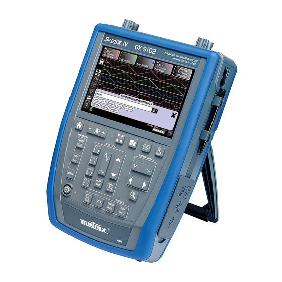
Description 2. DESCRIPTION 2.1. Front panel Probix terminal Hard enclosure covered with block elastomer, rated to IP54. Color screen Display of the applied signals, accompanied by all adjustment parameters. The screen is divided into The main command functional zones: display of the functions can be modified by zoom simultaneous with waveform, the touch screen using the... -
Page 12: Touch Screen And Stylus
Description 2.3. Touch screen and stylus Color screen: Display LCD WVGA (800x480) 7 inch resistive, color, touch operated (can be used with protective gloves) Backlighting by LEDs Brightness adjustable by the keypad Light sensor: automatically adjusts brightness to accommodate ambient light ... -
Page 13: Accessories
Description 2.4. Accessories Attaching the strap (length adjustable from 16.5 to 23.6” [42 to 60cm]) to the instrument: HX0122 strap with removable grip CLIC ! Attach the strap: Remove the strap: Stand providing an angle of 40° ShopAEMC www. 1.800.561.8187 Shop for AEMC products online at:... - Page 14 Description HX0120 The carrying/protection case includes: carrying waterproof all-terrain bottom case 2 handles shoulder strap removable interior compartment with 3 storage areas: - 1 central compartment with plasticized pouch for the ScopiX - 2 side pockets with 2 adjustable self-adhesive separators for storing accessories HX0121 stylus The stylus is stored in the holder on the side of the instrument.
-
Page 15: Communication Interfaces
Description 2.5. Communication interfaces Communication interfaces Communication ports are grouped in a dedicated compartment on the right side of the oscilloscope and protected by a removable cover. RJ45 Ethernet µ Probe USB connector SD card connector calibration (USB (SD, SDHC, (10/100 lugs Type B, 12Mb/s) -
Page 16: Getting Started
Getting Started 3. GETTING STARTED 3.1 General principles Dialog boxes are displayed at the bottom of the screen. They do not overlap the graph display area, providing an unobstructed view of the user's action on the channel. (Only adjustments related to the displayed graph remain displayed.) However, in some cases a virtual keypad appears to enable entering alphanumeric content;... -
Page 17: Home Key And Icon
Getting Started 3.5 HOME key and icon Action Result (on the screen) Return to the home screen from a Press the HOME measurement session. key on the keypad Directly access the instrument's operating modes: - oscilloscope - multimeter ... -
Page 18: Ox 9304 Functional Description
OX 9304 Functional Description 4. OX 9304 FUNCTIONAL DESCRIPTION 4.1 SCOPE mode Reference 4.1.1 Keys/ active keypad Brightness Full screen Screen shot Autoset memory "Home" Automatic measurements Horizontal Reference time base of the measurements Zoom Cursors Vertical adjustments Triggering ON/OFF key 4.1.2 Reference Memory adjustment In oscilloscope mode, pressing this key freezes the traces on the screen. -
Page 19: Measure Adjustment
OX 9304 Functional Description 4.1.4 MEASURE adjustment Activates/deactivates window that displays the 20 automatic measurements of the reference trace. Activates the 20 automatic measurements of the 4 traces with displacement by "scrolling". By default, cursors are activated with automatic measurements. - Page 20 OX 9304 Functional Description b) from the screen Click at top right in the screen, on the Time Base zone (see the image to the left). Description below of the Y(t) - Y(f) - XY display modes 1. Y(t): time-based view of a waveform Settings from 1ns to 200s No averaging...
- Page 21 OX 9304 Functional Description Displays extreme values of the signal, acquired between two samples of the acquisition memory. This mode: detects a false representation due to undersampling displays short-duration events (Glitch, ≤2ns). Whatever time base is used, with its corresponding sampling rate, events having a short duration (Glitch, ≤2ns) are displayed.
- Page 22 OX 9304 Functional Description Rectangle Hamming Hanning Blackman Flat top Before calculating the FFT, the oscilloscope weights the signal to be analyzed by a window that acts as a bandpass filter. The choice of window type is essential to distinguish the different spikes of a signal and make accurate measurements.
- Page 23 OX 9304 Functional Description Horizontal unit: This is displayed in place of the time base and is calculated from the sweep coefficient: 12.5 Unit in Sweep coefficient Vertical unit: The sub-menus provide two possibilities: a) Linear scale: by selecting the FFT menu, then linear scale in (V/div) = unit of the signal in its time-domain representation (V/div) b) Log scale: by selecting the FFT menu, then log (logarithmic) scale...
-
Page 24: Vertical Signal Ampitude Adjustment
OX 9304 Functional Description 4.1.6 Adjustment of the amplitude of the "VERTICAL" signal a) from the keypad Select channel Activate channel De-activate channel Adjust the vertical sensitivity of the last channel selected: Increase the vertical sensitivity ... - Page 25 OX 9304 Functional Description b) from the screen Defines the vertical scale of the selected channel. This produces a reading of the direct measurements of the quantity analyzed and of its unit. Example: Coupling: AC DC GND GND Coefficient: Assigns a multiplier coefficient to the sensitivity of the selected channel.
-
Page 26: Trigger Adjustment
OX 9304 Functional Description 4.1.7. Adjustment of the triggering level "TRIGGER" a) from the keypad Adjusts the triggering level on the mean value of the signal (50%) without modifying the coupling of the trigger. Pressing this button combined with a CHx key starts the same function, but first selects the corresponding channel as triggering source. - Page 27 OX 9304 Functional Description b) from the screen 1. Edge Selects a channel as triggering source: E.g. CH4 Triggering source Selects the filter of the main triggering source: AC coupling (10Hz to 300MHz): blocks the DC component of the signal. DC coupling (0 to 300MHz): passes the whole signal.
- Page 28 OX 9304 Functional Description Selects the width of the “triggering on pulse” value: 2. Pulse The edge is selected either in the "Trigger" tab or from the keypad and defines the limits of the analysis: edge defines a pulse between edge defines a pulse between In all cases, the actual triggering is on the end-of-pulse edge: t>T1...
- Page 29 OX 9304 Functional Description Selects delay: Triggering delay Pointing to this field opens a virtual digital keypad for direct entry of the value. Selection of triggering on edges with delay: Trigger Adjustments on the triggering source The delay is triggered by the auxiliary source. Actual triggering occurs on the next event in the main source after the end of the delay.
- Page 30 OX 9304 Functional Description Selects triggering on edge with counting of events. 4.Counting Qualifier Selects adjustments on the qualification source: 100 µs Disables triggering for a preset duration and (among other things) stabilizes triggering on pulse trains. Pointing to this field opens a virtual digital keypad for entering the value. Counting settings The counting is triggered by the auxiliary source;...
-
Page 31: Mathematical Function (From Screen)
OX 9304 Functional Description 4.1.8. MATHEMATICAL function, from the screen Defines, for each trace, a mathematical function and vertical scale Equation editor (functions, in the channels or simulated, programmable as F1, F2, F3, F4): Addition Subtraction Multiplication ... -
Page 32: Automatic Measurements (From Screen)
OX 9304 Functional Description 4.1.9. AUTOMATIC measurements, from the screen Opens the "Automatic measurements" Menu window of the channel Opens the "Automatic measurements" Menu window of the 4 channels Measurements are made and refreshed on the selected reference trace. All measurements that can be made on this trace are displayed. -
Page 33: Backup
OX 9304 Functional Description Automatic T = 1/F measurements Vmax 100% Vhigh >5%T Vavg Vamp Vpp Vlow Vmin Tfall Trise >5%T Positive overshoot = [100 * (Vmax – Vhigh)]/Vamp Negative overshoot = [100 * (Vmin – Vlow)]/Vamp ∑ Vrms −... -
Page 34: Multimeter Mode
OX 9304 Functional Description 4.2 Multimeter mode 4.2.1 Keys/keyboard active in Multimeter mode The ScopiX has a Multimeter function with 8000 display points. It has as many independent multimeters as there are channels in the Oscilloscope mode (2 or 4), with the same function as in the Oscilloscope mode: Probix. Coupling: If a channel is activated and selected, pressing this key changes the input coupling of the channel. -
Page 35: Icon/Screen Of The Multimeter Mode
OX 9304 Functional Description 4.2.2 Icon/screen of the Multimeter mode The channel is displayed in the color defined in Oscilloscope mode. Inactive channels are displayed in white. Display screen: 4 measurements 4 channels Several types of measurement are possible on CH1; the other channels are voltmeter channels only. -
Page 36: Adjustments Of The Vertical Menu
OX 9304 Functional Description Secondary If no display is selected, or if no display is possible (e.g. frequency measurement of a DC measurements signal, etc.), the string '-----' is displayed. If the channel is not selected, the string '-X-' is displayed. If the signal is outside of the range: "OL"... -
Page 37: Power Measurement
OX 9304 Functional Description 4.2.4 Power measurement Display The following secondary measurements are available in this quantity: MIN/MAX relative frequency Selecting distribution network type and power parameters ���� ∗ � ����(����) ∗ ����(����) Single-phase ���� ���� ���� Three-phase without neutral (two-wattmeter method) Available only for 4 channel instruments ����... -
Page 38: Logger Mode
OX 9304 Functional Description Clicking either icon exits Power mode. Configuration backup. 4.3. LOGGER mode 4.3.1 Keys/keyboard active in LOGGER mode When you enable LOGGER mode, a file is automatically generated. This file records up to 10,000 measurements in all active channels: duration of the record 20,000s, resolution 0.2s. -
Page 39: Icons/Screen In Logger Mode
OX 9304 Functional Description 4.3.2 Icons/screen in LOGGER mode LOGGER mode records measurements made in multimeter mode. Displays graphic time window, showing the time course of the measurements. The most recent measurements are on the right. The measurement cursors can be used. This indicator displays the reference channel: The time of the measurements is the... -
Page 40: Viewer Mode
OX 9304 Functional Description 4.4. VIEWER mode File manager Look-up files in internal memory and µSD Card Creates a new directory. Erases a directory or a file after confirmation. Duplicates a file. Renames a file from the alphanumeric keypad. Displays an analysis file, which opens in the mode recorded (except for .png screenshot files, which are opened in a specific viewer with file processing tools: erasure, printing, displacement of windows). - Page 41 OX 9304 Functional Description VIEWER Recalling a .rec file "VIEWER" file appears in the screen background and the LOGGER mode is identified by the icon at bottom right of the screen: Arrows for browsing from one file to another in the same directory. Search for events It is possible to search for events in VIEWER mode.
- Page 42 OX 9304 Functional Description Analyze events found. Pressing this icon opens a window containing the events meeting the search criteria. When an event is selected, the V1, V2, and T1 cursors appear. The associated measurements are displayed below the event window. The event name format is YYYY-MM-DD,HH :MM :SS .s where YYYY-MM-DD is the date of the record and HH :MM :SS.s is the value of the T1 cursor.
-
Page 43: Harmonic Mode
OX 9304 Functional Description 4.5. HARMONIC mode 4.5.1. Keys/keyboard active in Harmonic mode 4.5.2. Principle Harmonic mode Displays the breakdown into harmonics of a voltage or a current of which the signal is steady-state or quasi-steady-state. It establishes a first diagnostic of the harmonic pollution of an installation. -
Page 44: Icons/Screen In Harmonic Mode
OX 9304 Functional Description 4.5.3. Icons/screen in Harmonic mode Displays harmonic analysis of the selected traces. The harmonic analyses of traces ch1 and ch4 appear as solid-color bar charts, in the color of the trace. By default, the fundamental is selected automatically;... -
Page 45: Communication
OX 9304 Functional Description Exits Harmonic mode. Opens Help file. 4.6. Communication The communication interfaces are grouped in a dedicated compartment on the side of the ScopiX, protected by a removable cover. You can communicate on several interfaces: USB type B for communication with a PC The cord supplied connects to the USB type A port of a PC: transfer of file, programming using SCPI commands ... -
Page 46: General Parameters
OX 9304 Functional Description 4.6.1 General parameters Configuration Updates date (day, month, year) and time (hour, minute, second). The selection is made by the stylus, using the scroll bars on either side of the parameters to be adjusted. Date/Time The clock starts when the menu is closed. Selects language used in the menus. - Page 47 OX 9304 Functional Description IP address An IP address is coded in 4 bytes, displayed in decimal form. 132.147.250.10 Each field can be set between 0 and 255; the fields are separated by decimal points. Unlike the physical address, the IP address can be modified manually by the user or automatically by DHCP.
-
Page 48: Memory
OX 9304 Functional Description 4.7. Memory The files are stored in a specific partition. Backup memory File system: 1. on an µSD Card; the partitions of the µSD Card are accessible in the sdcard_pX directory 2. in the local file system Available memory ... -
Page 49: Firmware Update
OX 9304 Functional Description 4.8. Firmware update Firmware Periodically, an "update available" message may appear on the home screen, if the ScopiX is connected to Ethernet or WiFi: This message indicates update files have been downloaded transparently to the ScopiX : they are available for an update, which is recommended to obtain new functions, bug fixes;... -
Page 50: Scopenet Iv
OX 9304 Functional Description 4.9. ScopeNet IV When you have obtained the IP address of the ScopiX (DHCP or manual) using a browser, type 14.3.250.51/scopenet.html (for example) on your computer; the screen to the left appears. JAVA application PC is used to display the ScopeNet IV page. - Page 51 OX 9304 Functional Description File and backup management is performed on the PC. You can also store data in ScopiX. via USB. Backup in the various modes (Oscilloscope, Multimeter, Logger, Harmonic) is possible from the computer configuration files: "adjustments" for all modes ...
-
Page 52: Waveforms Display
Waveform Display 5. WAVEFORM DISPLAY 5.1 Manual display To view the signal and project it on the screen, be aware of the following characteristics: Coupling: note whether the signal is pure AC or has a DC component amplitude in Volts: defines the signal’s amplitude on screen ... -
Page 53: Using The Touch Screen
Waveform Display 5.1.2. Using the touch screen Icon Action Connect the Probix probe to the channel input. Click the channel key to refresh it ("channel activated") and access configuration. Select the coupling type. Press + or - to select the desired sensitivity of the channel or its maximum amplitude visible on screen. -
Page 54: Calibrating The Probes
Waveform Display 5.3 Calibrating the probes Step Action Connect the Probix adapter of an HX0030 probe having a 1/10 ratio to the CH1 input. Connect the probe (with its ground) to the calibrator output (Probe Adjust: ≈3V, ≈1kHz) on the side of the instrument. - Page 55 Waveform Display Compensation of Probix HX0030 compensation adjustment. the HX0030 probe For optimum response, use the knob at the top of the probe to adjust the low- frequency compensation of the probe so that the plateau of the signal is horizontal. Probe overcompensated Probe correctly compensated...
-
Page 56: Auto/Cursors/Zoom Measurement
Waveform Display 5.4 Auto/Cursors/Zoom measurement 5.4.1. Auto For optimum measurement accuracy, we recommend displaying two complete periods of one or more signals. To do this, modify the time base using the "horizontal" keys. There are two ways to start Auto measurements in a channel: ... -
Page 57: Cursors
Waveform Display Time measurements Level measurements Auto Measurements list rise time DC voltage fall time RMS voltage positive pulse peak-to-peak voltage negative pulse amplitude duty cycle max. voltage period min. voltage frequency upper plateau phase lower plateau counting overshoot integral 5.4.2. -
Page 58: Adjusting The Trigger
Waveform Display 5.5 Adjusting the Trigger Choose the triggering mode that corresponds to your application. Set the values of all triggering parameters. Example: Triggering on edge Exit from the window by clicking the cross. 5.6. Mathematical/FFT/XY measurement Mathematical functions These serve to process readings as a function of the settings configured on one of the channels of the instrument. - Page 59 Waveform Display This function is used to display one channel as a function of another. Parameters: Time base in seconds for channels X and Y Channel X or Channel Y Averaging: no, 2, 4, 16, 64 Mode: vector, envelope, whole acquisition, total The checkbox field “Repetitive signal”...
-
Page 60: Multimeter Measurements
Multimeter Measurement 6. MULTIMETER MEASUREMENT 6.1 Differentiating channels Channel 1 of the ScopiX is named CH1. It measures various physical quantities in addition to the signal amplitude measurements, using the appropriate Probix accessories. The other channels are voltmeter channels only (or current channels, when used with a Probix clamp). 6.2 Measurement type Measurements ... -
Page 61: Power Measurement
Multimeter Measurement Remarks The channels of the measurement ranges are automatic. To define the measurement range in manual mode, press the key. A long press on the channel key return to automatic mode. In addition: In automatic mode, the measurement range on the screen is highlighted in the color of the channel. -
Page 62: Logger Mode
Multimeter Measurement 6.4 LOGGER mode This function of Multimeter mode records values read on the various channels of the ScopiX, whatever the type of measurement. The records may be long. We suggest connecting ScopiX to external power to avoid measurement stoppage when the battery is depleted. -
Page 63: Harmonics Analysis
Harmonics Analysis 7. HARMONICS ANALYSIS You can change the displayed harmonic using the keys. The following values are displayeded: value in % of the harmonic of greatest amplitude phase in ° with respect to the fundamental frequency in Hz ... -
Page 64: Technical Specifications
Technical Specifications 8. TECHNICAL SPECIFICATIONS 8.1. Oscilloscope function Only the assigned tolerance or limit values are guaranteed values (after a half-hour warm-up period). The values without tolerances are given as an indication. Vertical deflection OX 9102 Characteristics OX 9062 OX 9304 OX 9104 Number of channels OX 9xx2: 2, OX 9xx4: 4... - Page 65 Technical Specifications Horizontal deflection (time base) Characteristics OX 9062 - OX 9102 - OX 9104 - OX 9304 Time base ranges 35 ranges, from 1ns to 200s/div. Accuracy of the time base ±[0.0005% + max (500ps, 1 sample)] 2.5GS/sec. in real time Sampling frequency 100GS/sec.
- Page 66 Technical Specifications Triggering circuit OX 9102 Characteristics OX 9062 OX 9304 OX 9104 CH1, CH2, CH3, CH4 (OX 9xx4) CH1, CH4 Triggering sources CH1, CH4 (OX 9102) Automatic Triggered Triggering mode Single-shot Auto Level 50% 10Hz to 100MHz 10Hz to 200MHz ≥10Hz BW on triggering 0Hz to 100MHz...
- Page 67 Technical Specifications Acquisition system Characteristics OX 9062 - OX 9102 - OX 9104 - OX 9304 ADC Resolution 12 bits 2.5GS/s in real time Maximum sampling frequency 100GS/s with repetitive signal (ETS) according to time base 1 converter per channel Minimum width of transients that can be detected: ≥...
- Page 68 Technical Specifications Measurement processing Mathematical functions Equation editor (functions on the channels or simulated functions): Addition, subtraction, multiplication, division, and complex functions between channels. Automatic measurements Time measurements Level measurements rise time DC voltage fall time RMS voltage positive pulse peak-to-peak voltage negative pulse amplitude...
- Page 69 Technical Specifications Display Characteristics OX 9062 - OX 9102 - OX 9104 - OX 9304 Display screen LCD 7’’ TFT (color display) Backlighting by LEDs Brightness Continuous adjustment Resolution WVGA, or 800 pixels horizontally x 480 pixels vertically Choice of delays: 15', 30', 1h, or none Screen saver Display without Zoom Complete memory: 100,000...
-
Page 70: Multimeter And Logger Function
Technical Specifications 8.2 Multimeter and LOGGER functions Only the assigned tolerance or limit values are guaranteed values (after a half-hour warm-up period). The values without tolerances are given as an indication. Display 8,000 points as voltmeter Input impedance 1MΩ Max. input voltage 600 Vrms sine and 800 VDC without probe 1000 Vrms and 1400 VDC with HX0030 probe DC measurement... - Page 71 Technical Specifications Resistance measurement In Channel 1 Ranges (full scale) Ohmmeter Resolution Measurement current 80Ω 0.01Ω 500µA 800Ω 0,1Ω 50µA 8kΩ 1Ω 50µA 80kΩ 10Ω 2µA 800kΩ 100Ω 2µA 8MΩ 1000Ω 50nA 32MΩ 10kΩ 50nA Accuracy ±(0.5% + 25 D) from 10% to 100% of the scale Open-circuit voltage ≈3V Continuity measurement...
-
Page 72: Viewer Function
Technical Specifications Operating modes Relative mode Display with respect to a base measurement The Relative, Surveillance, and On all measurements in MAX MIN value Surveillance (statistical) Frequency modes are mutually exclusive. Frequency The frequency can be displayed in AC mode Interval of time between 2 0.2s measurements... -
Page 73: Harmonic Analysis Function
Technical Specifications 8.4. HARMONIC ANALYSIS function Displays harmonics in bargraph form Crosshair with vertical axis graduated in % Horizontal axis graduated in orders of harmonic Displays 63 orders The harmonic analysis function can be implemented on the 4 channels ... -
Page 74: Communication
Technical Specifications 8.5. Communication 8.5.1. Communication port and peripherals ETHERNET 100Base-T, electrically isolated (peripheral) 600V, CAT III isolation is implemented inside the instrument. ETHERNET isolation by transformer USB isolation by logical isolator WIFI WEP, WPA Electrically isolated CDC (Communication Device Class) ACM (Abstract Control Model) protocol to submit SCPI queries MS (Mass Storage) protocol to manage the SCOPIX IV file system (and its µSD card). -
Page 75: General Specifications
General Specifications 9. GENERAL SPECIFICATIONS 9.1. Nominal range of use 9.1.1. Environmental conditions Reference temperature: 64 to 82°F (18 to + 28°C) Operation temperature: 32 to 104°F (0 to + 40°C) Storage temperature: -4 to 158°F (-20 to + 70°C) Relative humidity: <80% RH ... -
Page 76: Mechanical Specifications
General Specifications 9.2. Mechanical specifications 9.2.1. Case covered with elastomer Components: lower housing central belt holding all terminations upper housing battery compartment cover Dimensions: 11.5 x 8.3 x 2.6” (292.5 x 210.6 x 66.2mm) Weight: approximately 5.3 lbs (2.4 kg) with the battery Carrying strap: snaps onto the top of the instrument 9.2.2. -
Page 77: Line Power
General Specifications 9.3.2. Line power DC supply, approximately 15V, 30W for instrument operation DC supply, approximately 11V, 15W to charge the battery Primary circuit characteristics: 98V < Input voltage < 264V Therefore operates on the following networks: 230V, ±15%, 50Hz 115V, ±15%, 60Hz 9.4. -
Page 78: Temperature
General Specifications b) Input voltage: 9.4.3. Temperature Maximum internal temperature: 185°F (85°C) when the max. ambient temperature is 104°F (40°C). ShopAEMC www. 1.800.561.8187 Shop for AEMC products online at:... -
Page 79: Maintenance
Maintenance 10. MAINTENANCE 10.1. Warranty This oscilloscope is guaranteed for three (3) years against defects of materials or workmanship, in accordance with the general terms of sale. During this period, the instrument must be repaired only by the manufacturer, which reserves the right either to repair the instrument or to replace all or part of it.
Need help?
Do you have a question about the ScopiX IV Series and is the answer not in the manual?
Questions and answers