Metrix MX 350 User Manual
Ac clamp-on meter
Hide thumbs
Also See for MX 350:
- User manual (73 pages) ,
- User manual (68 pages) ,
- User manual (68 pages)
Table of Contents
Advertisement
Quick Links
Download this manual
See also:
User Manual
Advertisement
Table of Contents

Related Manuals for Metrix MX 350


Summary of Contents for Metrix MX 350
- Page 1 MX 350 Pince multimètre AC AC Clamp-on meter AC-Vielfachmesszange Pinza multimetro AC Pinza multímetrica CA MX 355 Pince multimètre AC/DC AC/DC Clamp-on meter AC/DC- Vielfachmesszange Pinza multimetro AC/DC Pinza multímetrica CA/CC...
- Page 2 Chapitre I User's manual Chapter II - page 17 MX 350 / MX 355...
-
Page 3: Table Of Contents
Hz frequency (Autorange) of a current .. 29 5.2.7. Hz frequency (Autorange) of a voltage .. 29 5.2.8. Safety ..........29 5.2.9. General information....... 29 5.3. Environmental conditions ......30 5.3.1. Temperature.......... 30 5.3.2. E.M.C..........30 5.4. Accessories..........30 MX 350 / MX 355... -
Page 4: General Instructions
CAT IV: CAT IV circuits are circuits which can carry very substantial transient over-voltage. Example: power feeders For your own safety, only used leads that comply with the IEC 61010 norm. Before using them, always check that they are in perfect working order. MX 350 / MX 355... -
Page 5: When Using The Instrument
This person is authorised to power up and power down installation equipment, compliance with safety regulations. 1.1.5. Cleaning Clean the instrument with a damp cloth and soap. Never use abrasive products or solvents. MX 350 / MX 355... -
Page 6: Warranty
Our products are patented in FRANCE and ABROAD. Our logos are registered trade marks. We reserve the right to modify the characteristics and prices should technological advances make it necessary. MX 350 / MX 355... -
Page 7: Description Of The Instrument
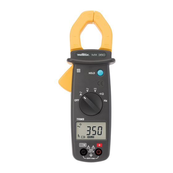
Chapter II DESCRIPTION OF THE INSTRUMENT 2.1. Description of front and rear Jaws Protective guard Trigger Switch Display COM input terminals + input terminals HOLD function Zero button Battery compartment MX 350 / MX 355... -
Page 8: Description Of The Display
Chapter II 2.2. Description of the display Batteries flat Automatic range Manual range Hold Continuity measurement Voltage measurement Current measurement Resistance measurement Alternating current Direct current Negative value Bargraph Frequency measurement DC zero/"delta" function MX 350 / MX 355... -
Page 9: General Description
"calibration value" subtracted from the measurements. 3.3. Memorization, automatic range It is possible to freeze the value displayed by pressing on the "HOLD" button. To deactivate this function, press the "HOLD" button a second time. MX 350 / MX 355... -
Page 10: Auto Cut-Off
"COM" input terminal. Then place the touch prods in contact with the points where the DC voltage is to be measured. Then read the result on the display. MX 350 / MX 355... -
Page 11: Measuring Ac Current
Close the clamp and read the result of the measurement the display. Note: For safety reasons, disconnect the measuring leads before performing this operation. If reading is difficult, press the HOLD button and read the result afterwards. MX 350 / MX 355... -
Page 12: Measuring Resistance
Connect the red test lead to the "+" terminal and the black test lead to the "COM" terminal. Place the touch prods in contact with the circuit to be tested. If the resistance is lower than 35 Ω, the buzzer sounds continuously. MX 350 / MX 355... -
Page 13: Measurement Of The Voltage Frequency
Note: For frequency measurements, you can use either the input terminals (voltage) or the jaws of the clamp (current). If you use both sources, the result of the measurement is false. MX 350 / MX 355... -
Page 14: Technical Specifications
1.5%R +5 D 600 V 400 V to 600 V 50 .. 500 Hz 1.5%R +5 D MX 350: Input impedance: 1 MΩ MX 355: Input impedance: 10 MΩ Protection against overloads: 660 Vrms 5.2.3. DC current (Autorange) (MX 355) -
Page 15: Resistance (Ω)
When a negative signal is applied, the signal appears. Overload If the range is exceeded, the symbol is displayed. Low battery indicator is displayed when the voltage supplied by the batteries is lower than the operating voltage. MX 350 / MX 355... -
Page 16: Environmental Conditions
APPENDIX: Reference conditions Sine signal: - Frequency from 48 to 65 Hz - No DC component Temperature 23°C ± 5°C External magnetic field < 40 A/m No AC magnetic field Measured conductor centred (in A) MX 350 / MX 355... - Page 17 METRIX Pôle Test et Mesure - CHAUVIN ARNOUX 190, rue championnet F - 75876 PARIX Cedex 18 Tel. 33 (0)1.44.85.44.85 - Fax 33 (0)1.46.27.73.89 Copyright © 906129581 - Ed. 03 - 01/05...
Need help?
Do you have a question about the MX 350 and is the answer not in the manual?
Questions and answers