Table of Contents
Advertisement
Quick Links
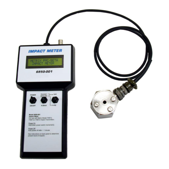
6850-001 Impact Meter
Installation Manual
6850 connected
to an IT6810
DOC# 100850 • REV B (April 2018)
OVERVIEW
The 6850 Impact Meter is designed for quick
check out or adjustment of Metrix Impact
transmitters, either on an operating ma-
chine, or with the transmitter removed.
Simply connect the Meter to an Impact
transmitter, toggle the Power switch, and
select Pulse-Time, 4-20mA, or Peak Detect
mode. In Pulse-Time mode, the transmit-
ter's Threshold level (milli-volts), and Sam-
ple Time (seconds) are displayed, and may
be adjusted while observing the changes.
Switching to 4-20mA mode displays the
current output directly, while Peak Detect
mode displays the peak vibration level, in
milli-volts, detected by the transmitter.
The Peak Detect mode is provided for
measuring and displaying the amplitude of
Impact peaks present at the measurement
location. Peak Detect mode is most useful
when "fine tuning" a transmitter for a par-
ticular machine. An Impact Threshold Level
2X to 3X the base line PD level has proven to
provide good machinery protection moni-
toring. While the Pulse Time is a function
of machine operating speed, calculated as
follows: 960 divided by machine RPM = the
Pulse Time (in seconds).
Advertisement
Table of Contents

Related Manuals for Metrix 6850-001


Summary of Contents for Metrix 6850-001
- Page 1 6850-001 Impact Meter Installation Manual OVERVIEW The 6850 Impact Meter is designed for quick check out or adjustment of Metrix Impact transmitters, either on an operating ma- chine, or with the transmitter removed. Simply connect the Meter to an Impact...
- Page 2 • Simple to operate for task efficiency 6850 OPERATION / OPERATING MODES The 6850 Impact Meter is designed for quick check out or adjustment of Metrix Impact transmitters, either on an operating machine, or with the transmitter removed. Simply connect the Meter to an Impact transmitter, toggle the Power switch, and select Pulse- Time, 4-20mA, or Peak Detect mode.
- Page 3 USING THE IMPACT METER The Impact Meter is capable of taking Threshold, Pulse Time, Loop Current, and Peak Detect measurements. Prior to taking measurements with the Impact Meter, you must connect the Impact Meter to your Impact Transmitter device as shown in Figure 1.
- Page 4 Peak Detect Measurement To initialize the Peak Detect measurement mode, set input switch 2 to Threshold, Pulse- Time, Peak Detect and input switch 3 to PD as shown in Figure 2. If the Impact Meter is already turned on, it will automatically detect the new switch setting and proceed with the Peak Detect measurement.
- Page 5 example, the displayed peak detect measurement for t1 as shown in Figure 8 is 320mV. This is the maximum impact level detected during the pulse time t1. During t2, the maximum impact level detected is 400mV. Since this value is greater than 320mV, the impact meter will display the new value of 400mV.
- Page 6 Dynamic Signal A BNC Connector is provided on the Impact Meter for viewing the impact waveform through the use of a scope or other measurement device. Battery Replacement The Impact Meter is designed to offer approximately 8 hours of continuous operation under normal conditions.
- Page 7 Doc# (April 2018) Page 7 of 8 100850 • REV B...
- Page 8 WEEE) should never be disposed of in the public waste stream. The “Crossed-Out Waste Bin” label affixed to this product is a reminder to dispose of this product in accordance with local WEEE regulations. If you have ques- tions about the disposal process, please contact Metrix Customer Services. info@metrixvibration.com www.metrixvibration.com 8824 Fallbrook Dr.
Need help?
Do you have a question about the 6850-001 and is the answer not in the manual?
Questions and answers