Table of Contents
Advertisement
Digital Proximity System
Operation and Maintenance Manual
100576 • REV C
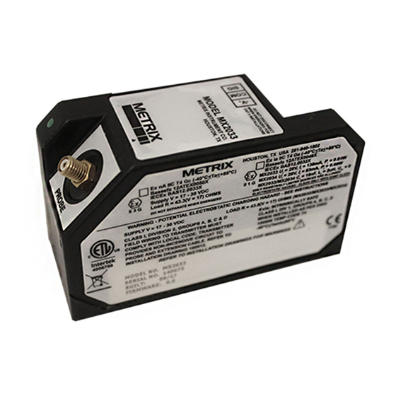
The DPS (Digital Proximity System) devices
consists of two modules: the MX2033 and
MX2034. The MX2033 is a conventional
3-wire driver while the MX2034 is a two-
wire current loop transmitter. Users can con-
figure either unit to measure peak-to-peak
vibration, gap distance, or rotational speed.
These products are used in conjunction with
a proximity probe and extension cable to
measure the vibration levels, gap distances,
or rotational speed of machinery shafts. Us-
ers can configure the units via a USB cable
and configuration software.
Advertisement
Table of Contents

Related Manuals for Metrix MX2033


Summary of Contents for Metrix MX2033
- Page 1 Digital Proximity System Operation and Maintenance Manual The DPS (Digital Proximity System) devices consists of two modules: the MX2033 and MX2034. The MX2033 is a conventional 3-wire driver while the MX2034 is a two- wire current loop transmitter. Users can con- figure either unit to measure peak-to-peak vibration, gap distance, or rotational speed.
-
Page 2: Table Of Contents
6.1.3 Metrix/BN 7200 5 Meter System ........ -
Page 3: General Information
1. GENERAL INFORMATION 1.1 SAFETY TERMS AND SYMBOLS Terms that appear in this manual requiring special attention include: • WARNING: Warning statements identify conditions or practices that could result in injury or loss of life. • CAUTION: Caution statements identify conditions or practices that could result in dam- age to the product, loss or corruption of data, or damage to the environment or other property. -
Page 4: Overview
If you see shipping damage, file a claim with the carrier and submit a copy to Metrix Instrument Co. Include part numbers and serial numbers on all correspondence. If no damage is apparent and the equipment is not going to be used imme- diately, return the equipment to the shipping containers and reseal until ready for use. -
Page 5: Mx2033 Three-Wire Proximity Driver
The sections below provide more module information. 2.1 MX2033 THREE-WIRE PROXIMITY DRIVER The MX2033 signal output is proportional to the distance between the probe tip and the target material. The signal output follows API Standard 670 and is compatible with most continuous vibration monitoring systems. -
Page 6: Configuring A Dps
3. CONFIGURING A DPS • This section lists the procedure for configuring a DPS: • Installing the DPS Configuration Software • Connecting a DPS to your computer • Retrieving the configurations from the DPS • Changing the DPS configuration for probe/cable type •... -
Page 7: Software Installation
3.2 SOFTWARE INSTALLATION Metrix provides the DPS Configuration and Utility Software on a USB memory stick that you request with the DPS (Refer to the DPS datasheet for software ordering information.) Insert the USB stick into your computer and open explorer to view the files. - Page 8 Figure 2 shows the end user license agreement. Click ‘Accept” to continue Figure 2: License Agreement Click Install to begin the installation Figure 3: Installation Screen Doc# (Sept 2017) Page 8 of 42 100576 • REV C...
- Page 9 If you are running Windows 7, Windows may present a User Account Control notice as shown in Figure 4. Click “Yes” to continue. Figure 4: Windows 7 User Account Control You may additionally see a Windows Security notice as shown in Figure 5. Click ”Install this driver software anyway”...
- Page 10 Click the Finish button as shown in Figure 6 to close the installation process. Figure 6: Installation Complete Screen Doc# (Sept 2017) Page 10 of 42 100576 • REV C...
-
Page 11: Connecting The Dps To A Computer
3.3 CONNECTING THE DPS TO A COMPUTER Follow these steps to access the DPS USB connector for connection to a computer. 3.3.1 REMOVE THE BASE Remove the three screws from the DPS base to access the mini USB connector as shown in Figure 7 and Figure 8. -
Page 12: Apply Power
(Refer to the DPS datasheet for volt- age and current requirements.) Powering is the same for either the MX2033 or the MX2034. The MX2034 does not require load resistors when configuring. -
Page 13: Main Screen
3.5 MAIN SCREEN The DPS Configuration Software opens with the main screen shown in Figure 10. Figure 10: The Main Screen 3.5.1 COMMAND LINE OPTIONS File – Exit the DPS Configuration Software. Print Labels – This opens the label printing screen to print updated side labels for their unit. This label contains basic configuration information as well as user specific information such as machine location, etc. -
Page 14: Device Communication Status
Date of Manufacture: Date the device was manufactured. Firmware Version: Firmware model and revision number Hardware Version: Hardware major.minor revision number Factory Calibration Date: Date of the last time Metrix calibrated the device Last Configuration Change: Date the configuration was last changed. 3.5.3 DEVICE COMMUNICATION STATUS... - Page 15 Figure 11: Configuring by Parameters 3.5.4.1 PROBE SERIES All DPS units support Metrix MX2030, Metrix 10,000 series 7200 compatible, Bently Nevada 3300, and Bently Nevada 7200 series probes. The DPS also supports one additional probe type specified at the time of ordering.
-
Page 16: Confirming The Configuration
3.5.4.4.2 AXIAL POSITION The MX2034 performs a displacement measurement for axial position and driver the 4-20 mA output proportional to the configured range. 3.5.4.4.3 SHAFT SPEED (RPM) MEASUREMENT The MX2034 performs a pulse count measurement cause by keyway and drives the 4-20 mA output proportional to RPM. - Page 17 This template is set for Avery 6570 label sheets of 32 labels (or equiva- lent). NOTE: User-printed labels should be secured under plastic overlay window. Order Metrix p/n 100527 DPS Label Printing Kit which contains instructions, Avery Labels, and overlays needed for printing up to 16 labels.
-
Page 18: Installing The Label
Figure 14: Selecting the label print start position Clicking a label starting point will open the printer selection screen. Select the printer and click OK to print. Figure 15: Selecting the printer 3.5.7 INSTALLING THE LABEL Remove the backing from the polycarbonate label and adhere the printed label inside the clear window. -
Page 19: Verification And Calibration
The scale factor of the output signal is 200 mV/ mil. Metrix recommends a maximum cable length of 15 ft (5 m) when connecting to the buffered output due to noise susceptibility caused by the high input and output impedances. -
Page 20: Scale Factor Verification
CAUTION: Do not connect test equipment or cables to the driver unless the area has been determined to be non-hazardous 4.1 SCALE FACTOR VERIFICATION Follow these steps in this section to verify the voltage output scale factor. The basic proce- dure is: Obtain the correct target material Assemble the test instruments and equipment... - Page 21 10 kohm resistor NOTE: Use the BNC connector on the MX2034 to verify the scale factor. The terminal strip signal pin is not used on the MX2034. Figure 17: MX2033 Scale Factor Validation Set Up Doc# (Sept 2017) Page 21 of 42 100576 •...
- Page 22 Figure 18: MX2034 Scale Factor Validation Set Up 4.1.1.3 ELECTRICALLY ZERO THE PROBE Set the probe gap “electrically” to the start of the measurement range by observing the DC output voltage and adjusting the probe position until the output is -1 V +/- 0.1 V at 10 mils gap.
- Page 23 4.1.1.4 MEASURE THE VOLTAGE IN GAP INCREMENTS Increase the micrometer 10 mil (0.25 mm) increments and fill in the measured SIG Voltage in the table below. Table 4: Verification Data Table mils SIG Voltage 0.25 0.50 0.75 1.00 1.25 1.50 1.75 2.00 2.25...
-
Page 24: Scale Factor Custom Calibration
You can easily custom calibrate the DPS for your probe following the procedure in this sec- tion. Perform the Scale Factor Verification as described in section 4.1. NOTE: The custom calibration process overwrites any previous custom calibration. Standard Metrix factory calibrations for MX2030 and 7200 5m and 9m systems are not affected. - Page 25 Fill in the voltages measured at each gap and then click the Generate and Load Linearization button. Figure 20: Filling in the Custom Calibration Voltages At completion, the following dialog box shows. Click OK to finish. Figure 21: Custom Calibration Successful Completion If the probe and cable run very far out of specification, the DPS may not be able to linearize the curve.
-
Page 26: Current Loop Verification (Mx2034 Only)
NOTE: Metrix does not recommend using the custom calibration feature to calibrate mismatched systems. Mis- matched systems degrade probe and cable temperature performance. - Page 27 Figure 23: Current Loop Validation Set Up At each gap, measure and record the SIG Voltage from the volt meter and the current output measured by the Ammeter. mils SIG Voltage Current 0.25 0.50 0.75 1.00 1.25 1.50 1.75 2.00 2.25 Use the following equation to determine the expected current at each gap.
- Page 28 Example: The configured range is 10 to 90 mils and the current gap is 30 mils. Bottom Scale Gap = 10 mils Top Scale Gap = 90 mils Current = 16 * (30 -10) / (90-10) ) +4mA = 8mA NOTE: Tolerance is + 0.15 mA.
-
Page 29: Troubleshooting
5. TROUBLESHOOTING 5.1 MX2033 AND MX2034 Symptom Possible Problems Recommended Action SIG stuck near -21V Probe is disconnected Verify that the probe is properly connected and the gap is in the OK region. SIG stuck at -Vt SiG shorted to power... -
Page 30: Mx2034 Only
5.2 MX2034 ONLY Symptom Possible Problems Recommended Action Maximum current below Loop resistance too large or Verify that total loop resis- 20 mA power supply too low. tance does not exceed the maximum per Installation Manual 100545. Current output stuck < 3.5 Probe is disconnected or out Verify that the probe is con- of range... -
Page 31: Performance Graphs
6. PERFORMANCE GRAPHS 6.1 DRIVER/TRANSMITTER TEMPERATURE RESPONSE Shown with custom calibration and represent typical performance over temperature, DPS unit only at temperature. 6.1.1 MX2030/BN 3300 5 METER SYSTEM Figure 24: MX2030 5m System, -35 C to +65 C Doc# (Sept 2017) Page 31 of 42 100576 •... - Page 32 Figure 25: MX2030 5m System DSL 0 C to 45 C Figure 26: MX2030 5m System DSL -35C to +65 C Doc# (Sept 2017) Page 32 of 42 100576 • REV C...
- Page 33 Figure 27: MX2030 5m System ISF, 0 C to 45 C Figure 28: MX2030 5m System ISF -35 C to + 65 C Doc# (Sept 2017) Page 33 of 42 100576 • REV C...
-
Page 34: Mx2030/Bn 3300 9 Meter System
6.1.2 MX2030/BN 3300 9 METER SYSTEM Figure 29: MX2030 9m System, -35 C to +65 C Figure 30: MX2030 9m System DSL, 0 C to +45 C Doc# (Sept 2017) Page 34 of 42 100576 • REV C... - Page 35 Figure 31: MX2030 9m System DSL, -35 C to +65 C Figure 32: Mx2030 9m System ISF, 0 C to +45 C Doc# (Sept 2017) Page 35 of 42 100576 • REV C...
-
Page 36: Metrix/Bn 7200 5 Meter System
Figure 33: MX2030 9m System ISF, -35 C to +65 C 6.1.3 METRIX/BN 7200 5 METER SYSTEM Figure 34: 7200 5m System, -35 C to +65 C Doc# (Sept 2017) Page 36 of 42 100576 • REV C... - Page 37 Figure 35: 7200 5m System DSL, 0 C to +45 C Figure 36: 7200 5m System DSL, -35 C to +65 C Doc# (Sept 2017) Page 37 of 42 100576 • REV C...
- Page 38 Figure 37: 7200 5m System ISF, 0 C to +45 C Figure 38: 7200 5m System ISF, -35 C to +65 C Doc# (Sept 2017) Page 38 of 42 100576 • REV C...
-
Page 39: Metrix/Bn 7200 9 Meter System
6.1.4 METRIX/BN 7200 9 METER SYSTEM Figure 39: 7200 9m System, -35 C to +65 C Figure 40: 7200 9m System DSL, 0 C to +45 C Doc# (Sept 2017) Page 39 of 42 100576 • REV C... - Page 40 Figure 41: 7200 9m System DSL, -35 C to +65 C Figure 42: 7200 9m System ISF, 0 C to +45 C Doc# (Sept 2017) Page 40 of 42 100576 • REV C...
-
Page 41: Phase Delay
Figure 43: 7200 9m System ISF, -35 C to +65 C 6.2 PHASE DELAY Figure 44 shows the expected phase shift error as the measured frequency increases. Figure 44: Phase Delay vs. Frequency Doc# (Sept 2017) Page 41 of 42 100576 •... -
Page 42: Trademarks And Copyrights
States and other countries. Microsoft, Excel, Windows, and Outlook and their respective designs are marks of Microsoft Corporation in the United States and other countries. © Copyright 2013, Metrix Instrument Company, L.P. All rights reserved. info@metrixvibration.com www.metrixvibration.com 8824 Fallbrook Dr. Houston, TX 77064, USA Tel: 1.281.940.1802 •...
Need help?
Do you have a question about the MX2033 and is the answer not in the manual?
Questions and answers