Advertisement
Quick Links
Download this manual
See also:
User Manual
Notice de fonctionnement
User's manual
Bedienungsanleitung
Libretto d'istruzioni
Manual de instrucciones
Copyright ©
MX 23
MULTIMETRE NUMERIQUE
DIGITAL MULTIMETER
DIGITAL MULTIMETER
MULTIMETRO DIGITALE
MULTIMETRO DIGITAL
page 1
Chapitre
page 12
Chapter
Seite 24
Kapitel
pagina 36
Capitolo
página 48
Capítulo
906129547 - Ed. 3 - 06/99
I
II
III
IV
V
Advertisement

Related Manuals for Metrix MX 23


Summary of Contents for Metrix MX 23
- Page 1 MX 23 MULTIMETRE NUMERIQUE DIGITAL MULTIMETER DIGITAL MULTIMETER MULTIMETRO DIGITALE MULTIMETRO DIGITAL Notice de fonctionnement page 1 Chapitre User's manual page 12 Chapter Bedienungsanleitung Seite 24 Kapitel Libretto d'istruzioni pagina 36 Capitolo Manual de instrucciones página 48 Capítulo Copyright ©...
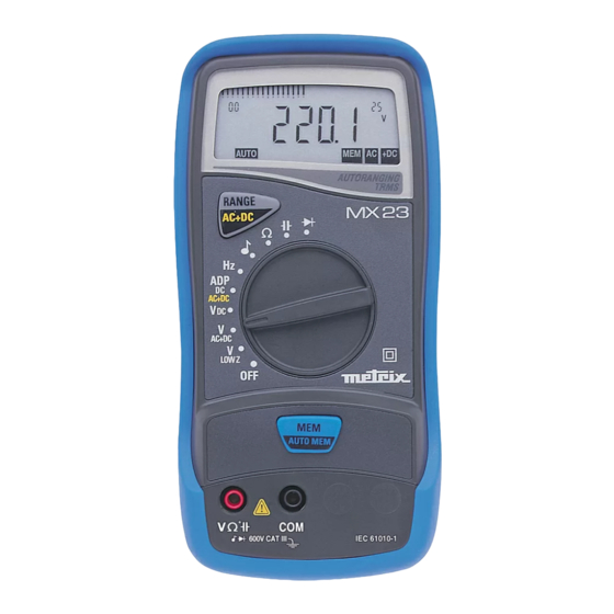
- Page 2 MX 23 MX 23 MX 23 MX 23 Multimètre digital portable 5000 points...
-
Page 3: Specifications Techniques
Chapitre I SPECIFICATIONS TECHNIQUES 5.1. Généralités Seules les valeurs affectées de tolérance ou les limites annoncées constituent des valeurs garanties. Les valeurs sans tolérance sont données à titre indicatif (norme NFC 42670) et les erreurs de mesure doivent être considérées dans les conditions de température de référence (voir §... - Page 4 Chapitre I 5.2.3. Résistances / Test de continuité ∗ Position du Gammes Précision Courant de mesure Résolution Protection( commutateur 500 Ω 0.1 Ω 0.3 %L + 3 UR 1 mA 500 Ω 0.1 Ω 1 mA 1 Ω 5 kΩ 0.3 %L + 3 UR 100 µA Ω...
- Page 5 Chapitre I 5.2.6. Mesure de tension de seuil diodes Tensions mesurables : 0 à 1.999 V 1 mA ± 20 % Courant de mesure : Résolution : 1 mV Protection : 600 V 5.2.7. Sécurité CEI 61010-1 + A1 + A2, 1995 Isolation : classe 2 Degré...
- Page 6 Chapitre I 5.2.10. CEM Cet appareil a été conçu conforme aux normes CEM en vigueur et sa compatibilité a été testée conformément aux normes suivantes : • Emission selon EN 50081-1, 1992 • Immunité selon EN 50082-1, 1997 Ce produit est conforme aux prescriptions de la directive européenne basse tension 73/23/CEE et à...
- Page 7 Chapter II USER'S MANUAL CONTENTS 1. GENERAL INSTRUCTIONS..................... 13 1.1. Precautions and safety measures ..................13 1.1.1. Preliminary........................13 1.1.2. During use ........................13 1.1.3. Symbols........................14 1.1.4. Instructions ........................14 1.2. Protection devices ......................14 1.3. Safety devices ........................15 1.4.
-
Page 8: General Instructions
Chapter II GENERAL INSTRUCTIONS You have just acquired a portable digital multimeter and we thank you for your confidence. This instrument complies with the specification of IEC 61010-1 + A1 + A2, 1995, publication concerning safety requirements for electronic measuring apparatus. To get the best service from this instrument, read carefully this user's manual and respect the detailed safety precautions. - Page 9 Chapter II ∗ Never exceed the protection limit values indicated in the specifications for each type of measurement. ∗ When the multimeter is linked to measurement circuits, do not touch unused terminals. ∗ When the scale of the value to be measured is unknown, check that the scale initially set on the multimeter is the highest possible or, wherever possible, choose the autoranging mode.
- Page 10 Chapter II ∗ A PTC (positive temperature coefficient) resistor protects against permanent overvoltages of up to 600 V during resistance, capacitance, continuity and diode test measurements. This protection is reset automatically after overload. ∗ The fuse provides protection while measuring Ω and testing diodes. ∗...
- Page 11 Chapter II DESCRIPTION This compact multimeter is a self-contained with an appropriate mechanical construction, enables hand-held version, with a protective elastomer case. This casing is sealed. It is designed for a high degree of user safety, maximum protection and unrivalled performance.
-
Page 12: Getting Started
Chapter II GETTING STARTED 3.1. Connecting the test leads Connect the black lead to the COM socket and connect the red lead to the other socket. 3.2. Switching on the instrument The selector switch is on the OFF position. Turn the selector switch to the required function. All segments of the display come on for a few seconds. - Page 13 Chapter II 3.5.3. Replacing the battery or the fuse Caution ! Disconnect test leads from any circuit under test, turn the meter off and remove test leads from the input terminals . Use the following procedure : 1 - Disconnect test leads from any inputs terminals. 2 - Using a appropriate tool, make slide the case bottom of the instrument.
- Page 14 Chapter II FUNCTIONAL DESCRIPTION 4.1. RANGE / AC+DC key The RANGE key is operative in following posiTIons of the selector switch : , Ω, LOW Z AC+DC This key makes it possible : • In AUTO (Autoranging) mode to switch to MANUAL mode (short press). •...
-
Page 15: Technical Specifications
Chapter II TECHNICAL SPECIFICATIONS 5.1. General Only the values assigned tolerances or given limits are guaranteed values. Values without tolerances are given for information only, without guarantee (standard NFC 42670). The measurement errors must be considered in an environment of reference temperature (refer to §... - Page 16 Chapter II 5.2.3. Resistance / Continuity test Selector switch Ranges Accuracy Measurement Protection (∗) Resolution position current 500 Ω 0.1 Ω 0.3 %R + 3 D 1 mA 500 Ω 0.1 Ω 1 mA 1 Ω 5 kΩ 0.3 %R + 3 D 100 µA 600 V Ω...
- Page 17 Chapter II 5.2.6. Diode threshold voltage measurement Measurable voltages : 0 to 1.999 V Measurement current : 1 mA ± 20 % Resolution : 1 mV Protection : 600 V 5.2.7. Safety IEC 61010-1 + A1 + A2, 1995 Insulation : class 2 Pollution degree : 2 Indoor use, altitude <...
- Page 18 Chapter II 5.2.10. EMC This apparatus was designed in accordance with the EMC standards in force and its compatibility has been tested accordance with the following standards : • Emission EN 50081-1, 1992 • Immunity EN 50082-1, 1997 The product conforms to the prescriptions of the European directive low voltage directive 73/23/EEC and the EMC directive 89/336/EEC, amended by 93/68/EEC.
Need help?
Do you have a question about the MX 23 and is the answer not in the manual?
Questions and answers