
Related Manuals for Pfeiffer Vacuum ACP 120G


Summary of Contents for Pfeiffer Vacuum ACP 120G
- Page 1 INSTALLATION INSTRUCTIONS Translation of the Original ACP 120G - ACG 600G Multistage Roots pump, industrial and dry...
- Page 2 These operating instructions describe all models and variants of your product. Note that your product may not be equipped with all features described in this document. Pfeiffer Vacuum constantly adapts its products to the latest state of the art without prior notice. Please take into account that online operating instructions can deviate from the printed operating instructions supplied with your product.
-
Page 3: Table Of Contents
Table of contents Table of contents About this manual Validity Applicable documents Products concerned Conventions 1.4.1 Pictographs 1.4.2 Target group 1.4.3 Instructions in the text 1.4.4 Labels 1.4.5 Abbreviations Safety General safety information Safety instructions Precautions Intended use Foreseeable misuse Transportation and Storage Receipt of the product Handling the pump... - Page 4 8.6.5 Installation of the transport devices on ACG 600G Decommissioning Shutting down for longer periods Recommissioning Disposal Malfunctions Service solutions by Pfeiffer Vacuum Accessories Technical data and dimensions 13.1 General 13.2 Technical data 13.3 Environmental characteristics 13.4 Cooling water characteristics 13.5 Nitrogen characteristics...
- Page 5 List of tables List of tables Tbl. 1: Oil capacity per housing Tbl. 2: Electrical characteristics of the motor Tbl. 3: Changing the wiring in the terminal box Tbl. 4: Troubleshooting guide Tbl. 5: Conversion table: Pressure units Tbl. 6: Conversion table: Units for gas throughput Tbl.
- Page 6 Nitrogen injection system Fig. 10: Description of the water circuit Fig. 11: ACP 120G Dimensions Fig. 12: Dimensions ACP 120G with converter (large volume version) Fig. 13: ACG 600G Dimensions Fig. 14: Dimensions ACG 600G with converter (large volume version) 6/56...
-
Page 7: About This Manual
Keep the manual for future consultation. 1.1 Validity This document is for customers of Pfeiffer Vacuum. It describe the function of the designated product and provide the most important information for safe usage of the product. The descriptions comply with applicable directives. All information provided in this document refer to the current development status of the product. -
Page 8: Instructions In The Text
The work described in this document must only be carried out by persons with suitable technical training (specialist staff) and who have undergone Pfeiffer Vacuum training. 1.4.3 Instructions in the text Usage instructions in the document follow a general structure that is complete in itself. -
Page 9: Abbreviations
About this manual Fig. 1: Safety label locations (ACG 600G) 1 Max. load (transport device) Hot surface 2 Fill with oil Fig. 2: Safety label locations (ACP 120G) 1 Hot surface Fill with oil 1.4.5 Abbreviations Frequency converter BF/FB Functional block Inlet flange Exh. -
Page 10: Safety
Safety 2 Safety 2.1 General safety information The following 4 risk levels and 1 information level are taken into account in this document. DANGER Immediately pending danger Indicates an immediately pending danger that will result in death or serious injury if not observed. ►... - Page 11 Safety WARNING Risk of electric shock due to non-compliant electrical installations This product uses mains voltage for its power supply. Non-compliant electrical installations or installa- tions not done to professional standards may endanger the user’s life. ► Only qualified technicians trained in the relevant electrical safety and EMC regulations are au- thorized to work on the electrical installation.
-
Page 12: Precautions
Safety WARNING Risk of burns in case of contact with hot surfaces Component temperature remains high, even after the pump has stopped. There is a risk of burns through contact with hot surfaces, especially at the pump exhaust. ► Wait for the product to fully cool down before working on it. ►... -
Page 13: Intended Use
Safety 2.4 Intended use ● The vacuum pump should only be used to generate a vacuum while pumping gases. ● The vacuum pump is designed to operate in industrial environments. ● The vacuum pump is used for pumping condensable vapors. ● The vacuum pump is used for continuously pumping for inlet pressure < 50 hPa. ●... -
Page 14: Transportation And Storage
Transportation and Storage 3 Transportation and Storage 3.1 Receipt of the product Condition of the delivery ● Check that the product has not been damaged during transport. ● If the product is damaged, take the necessary measures with the carrier and notify the manufacturer. - Page 15 5. Hoist up the pump and move it to its location. 6. Immobilize the pump on the installation (see chapter “Installation”, page 20). Fig. 4: Fitting the lifting strap on ACP 120G 1 Hoisting ring (x2) Casters (x4) 2 Locking foot (x4) 15/56...
-
Page 16: Storage
Transportation and Storage Handling the pump ACP 120G using a hoist When handling the pump, a lifting device appropriate for the weight of the product must be used. The weight and center of gravity are provided in the “Dimensions” chapter. - Page 17 4. When nitrogen starts flowing from the exhaust, seal it with the accessories provided. 5. Disconnect the nitrogen supply from the connector. Never store a pump that has been used! Return it to the service center (see chapter “Service solu- tions by Pfeiffer Vacuum”, page 43). 17/56...
-
Page 18: Product Description
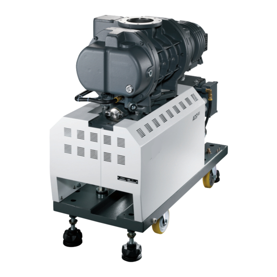
● 2 male/female NPT adapters 4.1.2 Product overview Based on the multi-stage Roots pump technology, the ACP 120G and ACG 600G models meet appli- cation requirements for a clean and oil-free vacuum, mainly in R&D and industry. They include a func- tional block pump and a Roots pump on certain models. - Page 19 Product description Fig. 6: ACG 600G Pump model description 1 Inlet flange (IN) Functional grounding 2 Nitrogen circuit inlet (N FB terminal box 3 Water circuit input/output (Water IN/Water OUT) Roots terminal box 4 Exhaust flange (Exh.) 19/56...
-
Page 20: Installation
NOTICE The product may be damaged if an unauthorized operating fluid is used The pumps are tested at the factory using Pfeiffer Vacuum oil. Using any other oil may adversely af- fect the pump and its performance. ► It is essential that the oil recommended by the manufacturer is used. -
Page 21: Connecting The Water Circuit
► Wear protective gear such as gloves, glasses and a mask when handling the oil. Safety data sheets You can obtain the safety data sheets for operating fluids from Pfeiffer Vacuum on request, or from the Pfeiffer Vacuum Download Center. -
Page 22: Nitrogen Circuit Connection
Installation NOTICE The water cooling circuit may be damaged if an unregulated mains supply is used Using unregulated mains water can lead to water circuit clogging due to limescale deposition. This may necessitate complete cleaning and overhaul of the water cooling circuit. Furthermore, the presence of micro-organisms such as algae and biological substances such as bacteria can lead to cooling problems in the pump. - Page 23 Installation WARNING Risk of injury in case of contact with pressurized nitrogen The product uses pressurized nitrogen as a flushing gas. Non-compliant installations or installations not done to professional standards may endanger the user’s life. ► Install a manual valve on the circuit at a distance of 3 m from the product, so that the nitrogen supply can be locked out.
-
Page 24: Electrical Connection
Installation 5.5 Electrical connection WARNING Risk of electric shock due to non-compliant electrical installations This product uses mains voltage for its power supply. Non-compliant electrical installations or installa- tions not done to professional standards may endanger the user’s life. ► Only qualified technicians trained in the relevant electrical safety and EMC regulations are au- thorized to work on the electrical installation. -
Page 25: Customer Electrical Installation Protection Measures
Installation 5.5.1 Customer electrical installation protection measures Circuit breaker protection The power circuit used to supply the pump must be fitted with a breaker complying with the IEC 60947-2 curve D standard whose short circuit cut-off capacity is at least 10 kA. This protection device should be in close proximity to the pump (no further than 7 m away) and in line of sight of the product. -
Page 26: Mains Connection
Installation Thermal safety connection 100 °C 120 °C 150 °C 1. Open the motor terminal box. 2. Pass the cable (customer supply) through the stuffing-box and wire the thermal safeties as shown. 3. Supply these NC contacts with a voltage of 250 V max. and a current of 0.5 A max. The ACG 600G pump is equipped with 2 motors. -
Page 27: Large Volume Pump Version Connection To The Mains
Installation The pump is equipped with a three-phase motor with 6 wires that are connected as indicated below. The motor is star wired when it leaves the factory. In case of doubt, only the plate in the terminal box should be used as a reference. In the ACG 600G, there are two motors. If motor wiring needs to be changed, proceed as follows: 1. -
Page 28: Connecting To The Pumping Line
Installation 1st step: Check the FB direction of rotation 1. Always check before starting the pump that the oil levels in the housings are at the mid-point of sight glasses. – This check should be done when the pump is stopped. 2. -
Page 29: Check That The Installation Is Leaktight
Installation WARNING Risk of crushing and/or cutting in case of contact with moving parts The pump inlet flange is large enough for body parts (fingers or hands) to the inserted into it, present- ing a risk of crushing due to contact with moving parts. The inlet and exhaust ports should be sealed with blanking plates before connection. -
Page 30: Operation
Operation 6 Operation 6.1 Preliminary precautions for use WARNING Risk of poisoning when process gases are present in the atmosphere The manufacturer has no control over the types of gases used with the pump. Process gases are of- ten toxic, flammable, corrosive, explosive and/or otherwise reactive. There is a risk of serious or fatal injury if these gases are allowed to escape freely into the atmosphere. -
Page 31: Advanced Settings
Advanced settings 7 Advanced settings This chapter describes the available functions and how they work. This chapter helps the user and/or the integrator to configure the pump parameters according to the requirements during the process. Management of warnings, alarms The management of warnings and alarms as defined in this manual must allow the monitor- ing of the operation of the pump according to the following principle: ●... -
Page 32: Description Of The Water Circuit
Advanced settings You are strongly advised not to stop the purge when the pump is running! Nitrogen flow fault indication It is advisable to install an alert system on the nitrogen circuit to indicate a flow malfunction. If the nitro- gen flow rate is below the set threshold, the system triggers an alert and/or an alarm when the delay has elapsed. -
Page 33: Monitoring Of The Exhaust Pressure
Advanced settings Roots Water IN Water OUT Exh. Fig. 10: Description of the water circuit 1 Water solenoid valve (supplied by the customer) Assembling recommendation ► Equip the cooling circuit with a regulation valve. 7.3 Monitoring of the exhaust pressure The monitoring of the exhaust pressure allows to check the level of clogging in the exhaust line. The pump is not equipped with a exhaust pressure monitoring device. - Page 34 Advanced settings Power Alarm message+ Warning warning message pump stopped 3000 W No message Time 60 s 34/56...
-
Page 35: Maintenance
Maintenance 8 Maintenance 8.1 Maintenance safety instructions DANGER Risk to health posed by residual traces of process gases inside the pump Process gases are toxic and hazardous to health. They can cause poisoning and be fatal. Before dis- connecting the pump, any remaining traces of process gases must be eliminated. ►... -
Page 36: Maintenance Frequency
The pump does not require any maintenance on the customer’s premises other than the day-to-day servicing described in this manual. All other maintenance must be carried out by your service center (see chapter “Service solutions by Pfeiffer Vacuum”, page 43). -
Page 37: Exchange Procedure For Replacement Products
Maintenance 1 CHc M4 x 20 screw (x3) O-ring 2 Protective cover Freeing up procedure To carry out this maintenance, it is necessary to use a 3 mm hexagonal key and a 21 mm female elbow Allen key. 1. Isolate and lock the power supply of the pump to turn it off. 2. -
Page 38: Draining The Water Circuit
Maintenance 5. Disconnect the WATER IN connector followed by the WATER OUT connector. 6. Disconnect the pump from the pumping line and blank off the inlet port with the airtight connection accessories (accessories). 7. Disconnect the pump from the exhaust and blank off the exhaust port with the airtight connection accessories (accessories). -
Page 39: Preparing The Pump For Shipping
Draining the pump The pump has 1 housing on the BF (ACP 120G) and 2 other housings on the Roots (ACG 600G). The draining procedure must be carried out for each one of the housings (see chapter “Filling with oil”, page... -
Page 40: Installation Of The Transport Devices On Acg 600G
Maintenance 8.6.5 Installation of the transport devices on ACG 600G 8 N·m 8 N·m 10 N·m 1 Side bar (x2) Hoisting ring (x2) 2 Left transport arch (x1) Screw H M6 x 20 (x4) 3 Top bar Feet (x4) 4 Screw H M8 x 35 (x2) Nut (x4) 5 Right transport arch (x1) Setting up the transport devices... -
Page 41: Decommissioning
All process pumps are designed for continuous operation in process gas pumping applications and should not be stopped. Pfeiffer Vacuum declines any liability for process pumps that have been stop- ped for a prolonged period of time leading to by-product condensation, powder build-up or corrosion inside the pump, nor does its warranty cover such items. -
Page 42: Malfunctions
Malfunctions 10 Malfunctions Malfunction and fault indications Pump malfunction indications depend on the control/monitoring system into which the pump is integrat- ed. The installation of a monitoring device is the responsibility of the integrator. Symptom Cause Remedy Vacuum poor or non-exis- Clogged pumps 1. -
Page 43: Service Solutions By Pfeiffer Vacuum
We are always focused on perfecting our core competence – servicing of vacuum components. Once you have purchased a product from Pfeiffer Vacuum, our service is far from over. This is often exactly where service begins. Obviously, in proven Pfeiffer Vacuum quality. - Page 44 Service solutions by Pfeiffer Vacuum 5. Prepare the product for transport in accordance with the provisions in the contamination declaration. a) Neutralize the product with nitrogen or dry air. b) Seal all openings with blind flanges, so that they are airtight.
-
Page 45: Accessories
Accessories 12 Accessories Accessory Function Dimension Isolation valve at pump Manual valve (Stainless DN 50 ISO-KF 30501M inlet steel) DN 100 ISO-K 30503M Electropneumatic valve DN 50 ISO-KF 30501E 24 VAC (Stainless steel) DN 100 ISO-K 30503E 1/4" NPT female con- Water input 101772 nector... -
Page 46: Technical Data And Dimensions
59.8 0.76 atm cm Tbl. 6: Conversion table: Units for gas throughput 13.2 Technical data Characteristics Unit ACP 120G ACG 600G Max.pumping speed. (50/60 Hz) 95/112 480/560 Ultimate pressure without N2 gas purge (50/60 Hz) 2 · 10 /5 · 10 2 ·... -
Page 47: Environmental Characteristics
Technical data and dimensions Characteristics Unit ACP 120G ACG 600G Weight dB(A) < 65 < 68 Noise level (maximum value) 1) This pump is certified for pumping a volume of 1 m , with 20-minute cycling. In case of larger volume or a higher cycling frequency, consult us.. -
Page 48: Cooling Water Characteristics
Technical data and dimensions 13.4 Cooling water characteristics 5.5 to 9 Chloride (ppm) Chlorides 100 to 20 ppm depending on the Hardness < 10 °fH (French degree) < 2 milliequivalent/L < 100 mg/L of CaCO (calcium carbonate) Total dissolved solids < 300 mg/L LSI (Langelier satura- - 0.5 <... -
Page 49: Dimensions
Main circuit breaker rating and cable cross-section size 13.7 Dimensions Dimensions in mm 55.7 WATER 726.7 Exh. WATER Fig. 11: ACP 120G Dimensions A Option inlet adapter 55.7 WATER 726.7 972.72 Exh. WATER Fig. 12: Dimensions ACP 120G with converter (large volume version) A Option inlet adapter 49/56... - Page 50 Technical data and dimensions WATER 55.7 591.7 WATER Exh. Fig. 13: ACG 600G Dimensions Exh. 55.7 Exh. WATER WATER Fig. 14: Dimensions ACG 600G with converter (large volume version) 50/56...
-
Page 51: Weight Distribution And Center Of Gravity
13.8 Weight distribution and center of gravity Exh. Ø16 Ø40 Center of gravity Sectional view Model Center of gravity (mm) Weight per foot (DaN) ACP 120G 163.4 331.5 315.1 74.7 35.4 51.9 Model Center of gravity (mm) Weight per foot (DaN) ACG 600G 75.4... -
Page 52: Maintenance Space Required
Technical data and dimensions 13.9 Maintenance space required 52/56... -
Page 53: Declaration Of Incorporation Of Partly Completed Machinery
Vacuum SAS (Simplified joint stock company), 98, avenue de Brogny B.P.2069, 74009 Ann- ecy cedex, France. Multi-stage Roots pumps ACP 120G - ACG 600G Harmonized standards and national standards and specifications applied: NF EN 1012-2 : 2009 NF EN 61010-1 : 2011... -
Page 54: Declaration Of Conformity
Transport device: lifting arches for ACG 600, ACG 1002 Part number : 128017 Harmonized standards and national standards and specifications applied: NF EN 1012-2: 2009 Signature: Pfeiffer Vacuum SAS 98, avenue de Brogny 74009 Annecy cedex France B.P. 2069 Bertrand Seigeot... - Page 55 55/56...
Need help?
Do you have a question about the ACP 120G and is the answer not in the manual?
Questions and answers