
Related Manuals for Pfeiffer Vacuum ACP 90


Summary of Contents for Pfeiffer Vacuum ACP 90
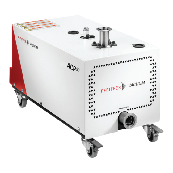
- Page 1 OPERATING INSTRUCTIONS Translation of the Original ACP 90 Multi-stage Roots pump, air cooled...
- Page 2 These operating instructions describe all models and variants of your product. Note that your product may not be equipped with all features described in this document. Pfeiffer Vacuum constantly adapts its products to the latest state of the art without prior notice. Please take into account that online operating instructions can deviate from the printed operating instructions supplied with your product.
-
Page 3: Table Of Contents
Table of contents Table of contents About this manual Validity 1.1.1 Applicable documents 1.1.2 Products concerned Target group Conventions 1.3.1 Instructions in the text 1.3.2 Pictographs 1.3.3 Labels Safety General safety information Safety instructions Precautions Intended use Foreseeable misuse Transportation and Storage Receipt of the product Handling Storage... - Page 4 Extended Immobilization Recommissioning Disposal Malfunctions Faults history The pump runs incorrectly The pump does not work Service solutions by Pfeiffer Vacuum Technical data and dimensions 11.1 General 11.2 Technical characteristics 11.3 Environmental characteristics 11.4 Nitrogen characteristics 11.5 Electrical characteristics 11.6 Dimensions...
- Page 5 List of tables List of tables Tbl. 1: Setting of the rotation speed Tbl. 2: Wiring the serial link on RJ45 connector Tbl. 3: Serial link connection settings Tbl. 4: Variable reading Tbl. 5: Response to the variable reading Tbl. 6: Variable writing Tbl.
- Page 6 Logic output wiring Fig. 5: Wiring the serial link on RJ45 connector Fig. 6: Dimensions (mm) ACP 90 (version SD / version G) Fig. 7: Position of center of gravity (mm) Fig. 8: Dimensions (mm) ACP 90 with casters option...
-
Page 7: About This Manual
Keep the manual for future consultation. 1.1 Validity These operating instructions are a customer document of Pfeiffer Vacuum. The operating instructions describe the functions of the named product and provide the most important information for the safe use of the device. The description is written in accordance with the valid directives. The information in these operating instructions refers to the product's current development status. -
Page 8: Conventions
About this manual 1.3 Conventions 1.3.1 Instructions in the text Usage instructions in the document follow a general structure that is complete in itself. The required ac- tion is indicated by an individual step or multi-part action steps. Individual action step A horizontal, solid triangle indicates the only step in an action. ►... -
Page 9: Safety Label Locations
About this manual This label warns users about the risk of crushing or cutting due to moving parts: keep a safe distance and/or keep your hands away from the moving MOVING PARTS PRESENT parts. Moving parts can crush and cut. Keep hands or feet away from moving parts. -
Page 10: Safety
Safety 2 Safety 2.1 General safety information The following 4 risk levels and 1 information level are taken into account in this document. DANGER Immediately pending danger Indicates an immediately pending danger that will result in death or serious injury if not observed. ►... - Page 11 Safety WARNING Danger of electrocution by contact during maintenance or overhaul There is an electric shock hazard in case of contact with a product powered on and not electrically isolated. ► Before carrying out any work, stop the pump. ► Disconnect the power cable from the mains. ►...
-
Page 12: Precautions
Safety 2.3 Precautions Duty to provide information on potential dangers The product holder or user is obliged to make all operating personnel aware of dangers posed by this product. Every person who is involved in the installation, operation or maintenance of the product must read, understand and adhere to the safety-related parts of this document. -
Page 13: Transportation And Storage
Transportation and Storage 3 Transportation and Storage 3.1 Receipt of the product Condition of the delivery ● Check that the product has not been damaged during transport. ● If the product is damaged, take the necessary measures with the carrier and notify the manufacturer. -
Page 14: Storage
2. Move the pump to position it on the installation. 3. Lock the casters to immobilize the pump. 3.3 Storage Pfeiffer Vacuum recommends storing the products in their original transport packaging. Storing a new pump 1. Keep the pump wrapped in its protective envelope. -
Page 15: Product Description
(see chapter “Electrical Characteristics”). In order to satisfy most applications in the 90 m /h range, the ACP 90 is available in 2 versions. Standard SD version The pump is designed for clean (dust-free) and non-corrosive gas pumping applications. Standard pumps are equipped with a gas ballast device to improve pumping of light gases and avoid vapor con- densation inside the pump. -
Page 16: Human/Machine Interface
Product description 4.2 Human/Machine Interface 1 ON/OFF manual gas ballast (SD version) Serial link connector (RS PORT) 2 Continuous gas ballast (SD version) Remote control connector (REMOTE PORT) 3 Gas ballast closed with a plug (SD version) Indicator light (MAINTENANCE) 4 Inert gas purge connection (G version) CPC Earth 5 Pump inlet Power supply connection... - Page 17 Product description Description Functions Display A four-digit monitor displays the following, depending on the operating modes. Running mode ● Operating status information (for example: frequency, current or voltage) ● “L-AL” to signal an alert Programming mode ● Menus, function codes and their values Alarm mode ●...
-
Page 18: Installation
Installation 5 Installation 5.1 Installation The pump needs to operate in the horizontal position resting on its feet, the pumping axis must be verti- cal, and the pump inlet must be on top. 1. Determine where the pump will be located. 2. Handle the pump using a hoist. 3. -
Page 19: Connection On The Pump Inlet Side
The purge consists of injecting an inert gas into the pump. In this manual, the inert gas will be called 'nitrogen', as it is the most commonly used gas. For more information on the type of purge gas, contact our Pfeiffer Vacuum service center. 19/52... -
Page 20: Check That The Installation Is Leak Tight
Installation DANGER Danger of death by explosion when pumping gases containing pyrophoric/flammable materi- There is a risk of explosion if pyrophoric materials above the LEL are sent to the pump. ► Ensure there is a sufficient flow of nitrogen to lower the concentration below the LEL. ►... -
Page 21: Customer Electrical Installation Protection Measures
Installation NOTICE Risk of electromagnetic disturbance Voltages and currents can induce a multitude of electromagnetic fields and interference signals. In- stallations that do not comply with the EMC regulations can interfere with other equipment and the environment in general. ► Use shielded cables and connections for the interfaces in interference-prone environments. Electromagnetic compatibility The product complies with industrial environment immunity and emission standards. -
Page 22: Connecting The Single-Phase Power Supply
Installation 5.4.2 Connecting the single-phase power supply 70 mm 60 mm 1 Power supply Electrical cabinet 2 CPC Earth connection Earth stud Preparation and connection The power supply is the responsability of the customer. It shall have suitable protection against ground- ing faults and the earth wire is longer than the conductor wires (see chapter “Electrical Characteristics”). -
Page 23: Connecting The Three-Phase Power Supply
Installation 5.4.3 Connecting the three-phase power supply 70 mm 60 mm 1 Power supply Electrical cabinet 2 CPC Earth connection Earth stud Preparation and connection The power supply is the responsability of the customer. It shall have suitable protection against ground- ing faults and the earth wire is longer than the conductor wires (see chapter “Electrical Characteristics”). -
Page 24: Cover Plug Wiring
Installation ● remote control of following functions: start, stop of the pump, ● set the rotation speed, ● remote pump status through auxiliary dry contacts. The remote control connector wiring is the customer's responsibility. 5.5.1 Cover plug wiring Fig. 2: Cover plug wiring The cover plug, supplied with the pump, allows automatic starting of the pump in LOCAL mode (see chapter “LOCAL mode operation with auto-start”). -
Page 25: Logic Output Wiring
Installation Contact Rotation speed 3600 2400 Tbl. 1: Setting of the rotation speed 5.5.4 Logic output wiring Fig. 4: Logic output wiring A Internal wiring Wiring from customer’s side Contact Function (2-6) Isolation valve control Contact opened as soon as a ‘STOP’ order is sent to the pump. Contact closed 2 seconds after sending a ‘RUN’... -
Page 26: Wiring The Serial Link
Installation 5.6.1 Wiring the serial link D0– Fig. 5: Wiring the serial link on RJ45 connector Not connected Not connected Not connected Differential data (RS-485) Differential data (RS-485) Ready to send Not connected Signal ground Tbl. 2: Wiring the serial link on RJ45 connector Transmission speed 9600 Bauds Parity... -
Page 27: List Of Variables
Installation Pump ad- Function Variable ad- Number of Number of Value to en- CRC16 dress code dress words bytes AA AA BB BB ZZ ZZ CC CC Tbl. 6: Variable writing Pump address Function code Variable address Number of words CRC16 AA AA BB BB... -
Page 28: Operation
● Do not drain the pump: this operation is carried out during pump overhaul by our serv- ice centers. Safety data sheets You can obtain the safety data sheets for operating fluids from Pfeiffer Vacuum on request, or from the Pfeiffer Vacuum Download Center. -
Page 29: Matrix Gas/Applications
Operation 5. Check that the ambient temperature is well within the permitted operating range. 6. Check the exhaust line during pumping to prevent the risks related to excess overpressure. 6.2 Matrix gas/applications You are advised to use the appropriate pump version according to the applications and the nature of the gases pumped and apply the usual precautions to guarantee the reliability and safety of the procedure. -
Page 30: Local Mode Operation With Auto-Start
Operation ● LOCAL ─ With automatic start-up: the pump starts automatically when it is switched on. ─ No automatic start-up: the pump is managed by the RUN/STOP keys on the frequency con- verter control pad. The pump runs independently of the equipment onto which it has been in- tegrated. -
Page 31: Local Mode Operation Without Auto-Start
Operation 6.3.2 LOCAL mode operation without auto-start Starting the pump The cover plug is not on the remote control connector. 1. Power on the pump. – The fan starts. – The frequency converter display shows 0.00, the KEYPAD CONTROL, Hz and A indicators are on. -
Page 32: Operation In Serial Link Mode
Operation Influence of rotation speed on pump performances Pump performances are guaranteed for a nominal speed of 112 Hz. Changing the rotation speed affects the pumping speed and the ultimate pressure of the pump. At low speed, it is the customer's responsibility to find the correct settings according to the pump and the process. -
Page 33: Gas Ballast Operation
Operation Shutting down the pump 1. Isolate the pump in the pumping line (isolation valve at pump inlet, closed) and let it to run for 1 hour with gas ballast or purge open 2. Send a ’STOP’ pump order via the serial link. –... - Page 34 Operation When the neutral gas supply is connected to a purge connection: 1. Start the purge according to the recommended flow rate value (see chapter “Technical character- istics”). Recommendations See chapter “Matrix gas/applications”. 34/52...
-
Page 35: Maintenance
Maintenance 7 Maintenance 7.1 Maintenance safety instructions DANGER Risk to health posed by residual traces of process gases inside the pump Process gases are toxic and hazardous to health. They can cause poisoning and be fatal. Before dis- connecting the pump, any remaining traces of process gases must be eliminated. ►... -
Page 36: Operating Time
(see chapter “List of variables”, page 27) 7.3 Maintenance frequency Operation Frequency Pump overhaul by the Pfeiffer Vacuum service center 24,000 hours or 4 years The MAINTENANCE indicator, at the rear of the pump, lights up when the 24,000 hours threshold is reached. -
Page 37: On-Site Maintenance
Any other maintenance operation must be carried out by our service center (see chapter “Service solutions by Pfeiffer Vacuum”, page 42). ► Clean the outer surfaces of the product using a clean, lint-free cloth and a product that will not damage the screen-printed surfaces and adhesive labels. -
Page 38: Preparing The Pump For Shipping
● Connect the cover plug (delivered with the pump) to the remote connector. Product transport and shipping For product transport and shipping, pack it in the original packaging and follow the instructions from the Service procedure (see chapter “Service solutions by Pfeiffer Vacuum”, page 42). 38/52... -
Page 39: Decommissioning
The manufacturer shall only be required to take back equipment that is complete and unmodified, using Pfeiffer Vacuum SAS original spare parts, sold by Pfeiffer Vacuum and including all assemblies and sub-assemblies. This obligation does not cover the shipping cost to a reclamation facility or services provided, for which the customer will be invoiced. -
Page 40: Malfunctions
Malfunctions 9 Malfunctions 9.1 Faults history For a fault diagnosis, it is necessary to know the last faults that occurred on the pump. The last 4 alarms are recorded. This history is not cleared when the power is turned off. It is possible to read the alarms on the frequency converter display or via the serial link. Reading on display The frequency converter displays the last 4 alarms. -
Page 41: The Pump Does Not Work
Malfunctions Symptom Cause Remedy Bad ultimate pressure Gas ballast ● Check if the gas ballast is open. Warning: if the application re- quires it, the gas ballast must remain open at the expense of the limit pressure! Purge (if present) ●... -
Page 42: Service Solutions By Pfeiffer Vacuum
We are always focused on perfecting our core competence – servicing of vacuum components. Once you have purchased a product from Pfeiffer Vacuum, our service is far from over. This is often exactly where service begins. Obviously, in proven Pfeiffer Vacuum quality. - Page 43 Service solutions by Pfeiffer Vacuum 5. Prepare the product for transport in accordance with the provisions in the contamination declaration. a) Neutralize the product with nitrogen or dry air. b) Seal all openings with blind flanges, so that they are airtight.
-
Page 44: Technical Data And Dimensions
Technical data and dimensions 11 Technical data and dimensions 11.1 General Basic principles for the Technical Data of Pfeiffer Vacuum dry compact multi-stage Roots pumps: ● ISO 21360; 2007: “Vacuum technology - Standard methods for measuring vacuum-pump perform- ance - General description”... -
Page 45: Environmental Characteristics
Technical data and dimensions Characteristics ACP 90 SD ACP 90 G Full load current (200-240 V 1-phase) 16.4 A Full load current (200-240 V 3-phase) 13.2 A Full load current (380-480 V 3-phase) 8.2 A Fan flow 430 m Weight 75 kg 1) In accordance with IEC/UL/CSA regulations, the pumps can withstand a voltage variation of ±... -
Page 46: Electrical Characteristics
Technical data and dimensions 11.5 Electrical characteristics Circuit breaker short circuit cut-off capacity 10 kA GFI (or RCD) type B, differential circuit breaker compatible with TT electrical networks 30 mA 1) for TN and IT networks, use appropriate protection measures Tbl. 14: Electrical network protection Mains power supply Single-Phase... -
Page 47: Dimensions
Technical data and dimensions 11.6 Dimensions Exh. Exh. Fig. 6: Dimensions (mm) ACP 90 (version SD / version G) A 1/4 BSPP purge connection for G version Fig. 7: Position of center of gravity (mm) Center of gravity 47/52... -
Page 48: Dimensions (Mm) Acp 90 With Casters Option
Technical data and dimensions Exh. Exh. Fig. 8: Dimensions (mm) ACP 90 with casters option A 1/4 BSPP purge connection for G version 48/52... -
Page 50: Declaration Of Conformity
EN IEC 61000-6-2: 2019 EN IEC 61000-6-4: 2019 The manufacturer's authorized representative in the United Kingdom and the authorized agent for compiling the technical documentation is Pfeiffer Vacuum Ltd, 16 Plover Close, In- terchange Park, MK169PS Newport Pagnell. Signature: Pfeiffer Vacuum SAS... -
Page 51: Ec Declaration Of Conformity
Declaration for product(s) of the type: Multi-stage Roots Pump, air cooled ACP 90 SD - ACP 90 G We hereby declare that the listed product satisfies all relevant provisions of the following European Directives. Machinery 2006/42/EC (Annex II, no. 1 A)
Need help?
Do you have a question about the ACP 90 and is the answer not in the manual?
Questions and answers