Table of Contents
Advertisement
Advertisement
Table of Contents

Related Manuals for Eliwell ICPlus 902


Summary of Contents for Eliwell ICPlus 902
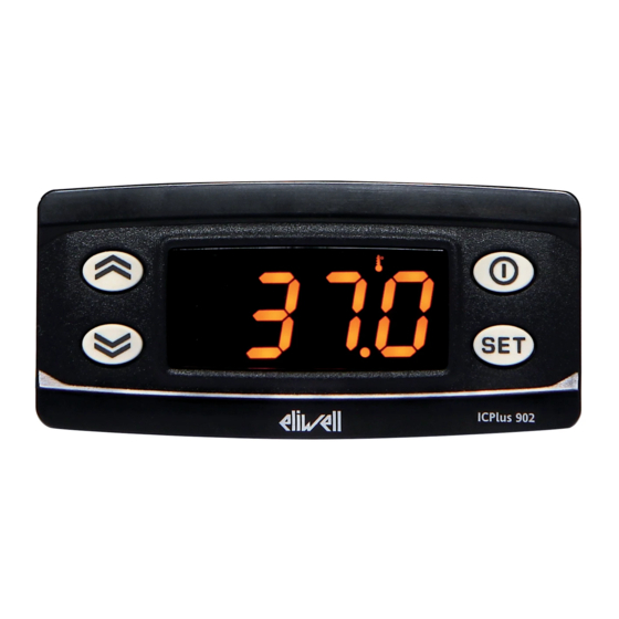
- Page 1 ICPlus 902 Electronic controller with 1 intervention point...
-
Page 2: User Interface
USER INTERFACE ICPlus 902 KEYS STAND-BY (ESC) Press and release Press and release Scroll menu items Returns to the previous menu level Increases values Confirms parameter value Press for at least 5 sec Press for at least 5 sec Function can be configured by the user (H31) - Page 3 ICONs Decimal Point Temperature Permanently on: decimal point Permanently on: displays a temperature Flashing: Soft Start active Flashing: reduced set active, displays a temperature or no unit of Off: otherwise measure selected Pressure Humidity Permanently on: displays a pressure Permanently on: displays a humidity Flashing: reduced set active and displays Flashing:...
- Page 4 NTC/PTC MODEL CONNECTIONS INPUT/OUTPUT CHARACTERISTICS NTC: -50...110°C (-58...230°F) NTC/PTC - 12V, 12-24V PTC: -50...140°C (-58...302°F) Display range: OUT1 on display with 3½ digits + sign 1 NTC or 1 PTC Analogue input (selectable by parameter H00) 9 10 11 TTL for connection to Copy Card or Supply Serial Televis/Modbus remote control systems...
- Page 5 NTC/PTC MODEL (with 2HP relay) CONNECTIONS INPUT/OUTPUT CHARACTERISTICS NTC: -50...110°C (-58...230°F) NTC/PTC - 12V (2 Hp) PTC: -50...140°C (-58...302°F) Display range: OUT1 on display with 3½ digits + sign 1 NTC or 1 PTC Analogue input (selectable by parameter H00) 9 10 11 TTL for connection to Copy Card or Supply...
- Page 6 V/I MODEL CONNECTIONS INPUT/OUTPUT CHARACTERISTICS -199...199 (ndt = n) V/I - 12V, 12-24V -199.9...199.9 (ndt = y) Display range: OUT1 -1999...1999 (ndt = int) on display with 3½ digits + sign 1 V/I (0-1V, 0-5V, 0-10V, 0...20mA, 4...20mA) 9 10 11 12 (selectable by parameter H00) −...
- Page 7 PT100/Tcj-Tck MODEL CONNECTIONS INPUT/OUTPUT CHARACTERISTICS PT100/Tcj-Tck - 12V, 12-24V PT100: -150...650°C TcJ: -40...750°C OUT1 Display range: TcK: -40...1350°C on display with 3½ digits + sign 10 11 12 1 PT100 or 1 TcJ / Tck Analogue input Supply (selectable by parameter H00) −...
-
Page 8: Mounting Dimensions
PT100/Tcj-Tck MODELs 0.5% for whole scale + 1 digit ACCURACY: PT100: 0.2% from -150 to 300°C RESOLUTION: 0.1°C (0.1°F) from -199.9°C up to 199.9°C; 1°C (1°F) beyond ACCURACY: 0.4% for whole scale + 1 digit TcJ: RESOLUTION: 0.1°C (0.1°F) from -199.9°C up to 199.9°C; 1°C (1°F) beyond 0.5% for whole scale + 1 digit ACCURACY: Tck:... - Page 9 EWPA-EWHS PROBE CONFIGURATION EWHS 284 2 wires EWHS 304/314 3 wires 9 10 11 12 9 10 11 12 Probe Probe RH/T blue GND (only EWHS314) brown EWHS 314 4 wires (V-I model) EWPA 007/030 2 wires / Transducer ICPlus 1 ICPlus 2 9 10 11 12 9 10 11 12...
-
Page 10: Using The Copy Card
USING THE COPY CARD The Copy Card is connected to the serial port (TTL) and allows rapid programming of the instrument parameters. Access Installer parameters by entering ‘PA2’ , scroll through the folders using until folder FPr appears. Select it using , scroll through the parameters using , then select the function using (eg. -
Page 11: Accessing And Using The Menus
ACCESSING AND USING THE MENUs The resources are organized into 2 menus which are accessed as follows: • ‘Machine Status’ menu: press and release the key. • ‘Programming’ menu: hold down the key for 5 seconds. Either do not press any keys for 15 seconds (timeout) or press the key once, to confirm the last value displayed and return to the previous screen. -
Page 12: Machine Status Menu
MACHINE STATUS MENU Access the Machine Status menu by pressing and releasing the key. If no alarms are active, the ‘SEt’ label appears. Use the keys to scroll through all the folders in the menu: - AL: alarms folder (only visible if an alarm is active); - SP1: Setpoint 1 setting folder;... - Page 13 DIAGNOSTICS Alarms are always indicated by the alarm icon and the buzzer. To switch off the buzzer, press and release any key; the corresponding icon will continue to flash. N.B.: If alarm exclusion times have been set (see ‘AL’ folder in the parameters table) the alarm will not be signalled. ALARMS Label Fault...
- Page 14 TELEVIS SYSTEM The Televis remote control systems can be connected using the TTL serial port (TTL-RS485 BusAdapter 130 or 150 interface ICPlus module must be used). To configure the instrument to do this, you need to access the Add folder and use the dEA and FAA parameters. RS485 IMPORTANT! CHECK THE AVAILABILITY OF MODELS COMPATIBLE WITH REMOTE SUPERVISION SYSTEMS.
- Page 15 TECHNICAL DATA (EN 60730-2-9) Classification: operation (not safety) device for incorporation Mounting: panel mounting with 71x29 mm (+0.2/-0.1 mm) drilling template Type of action: Pollution class: Material class: IIIa Overvoltage category: Rated impulse voltage: 2500V Temperature: Operating: –5 … +55 °C - Storage: –30 … +85 °C •...
-
Page 16: Further Information
• climate range A • measurement class 1 in the range from -25°C to 15°C (*) (* exclusively using Eliwell probes) NOTE: The technical specifications given in this document regarding measurement (range, accuracy, resolution, etc.) refer to the instrument and not to any accessories provided, such as the probes. This means, for example, that the error introduced... -
Page 17: Parameters Table
PARAMETERS TABLE PAR. DESCRIPTION MODEL RANGE VALUE M.U. LEVEL NTC/PTC °C/°F Temperature control setpoint SP1. The SEtpoint is visible from the PT100-Tc LS1...HS1 °C/°F machine status menu and not from the programming menu. CONTROLLER 1 (folder ‘rE1’) This sets the controller 1 operating mode. flag Inst H (0) = Hot;... - Page 18 PAR. DESCRIPTION MODEL RANGE VALUE M.U. LEVEL Delay time after switching off. The indicated time must elapse between 0...250 Inst deactivation of the controller 1 relay and the next switch-on. 0 = not active. Delay between switch-ons. The indicated time must elapse between two 0...250 Inst consecutive switch-ons of regulator 1.
- Page 19 PAR. DESCRIPTION MODEL RANGE VALUE M.U. LEVEL DISPLAY (folder ‘diS’) LOCk. Setpoint edit lock. The parameter programming menu can still be accessed, and the settings changed, which means also that the status of this flag User/Inst parameter can be changed so as to unlock the keypad. n (0)= no; y (1) = yes. Password 1.
- Page 20 PAR. DESCRIPTION MODEL RANGE VALUE M.U. LEVEL CONFIGURATION (folder ‘CnF’) If one or more parameters are changed, the controller MUST be switched off and switched on again. Probe type selection. NTC/PTC Ptc/ntC flag • NTC/PTC: Ptc (0) = PTC, ntC (1) = NTC PT100-Tc Jtc/Htc/Pt1 •...
- Page 21 PAR. DESCRIPTION MODEL RANGE VALUE M.U. LEVEL H33 Configuration of ESC key. Same as H31. 0...7 Inst rEL firmware version. Device software release: read-only parameter. User/Inst tAb Parameters table. Reserved: read-only parameter. User COPY CARD (folder ‘FPr’) UL Upload. Transfer of programming parameters from instrument to Copy Card. Inst Download.
-
Page 22: Electrical Connections
ELECTRICAL CONNECTIONs Attention! Make sure the machine is switched off before working on the electrical connections. The instrument is equipped with screw or disconnectable terminal blocks for connecting electrical cables with a max. diameter of 2.5 mm (one wire per terminal for power connections): for the terminal ratings, see the label on the instrument. Do not exceed the maximum permissible current;... -
Page 23: Liability And Residual Risks
• installation/use on panels not complying with current standards and regulations. DISCLAIMER This document is the exclusive property of ELIWELL CONTROLS SRL and may not be reproduced or circulated unless expressly authorised by ELIWELL CONTROLS SRL itself. Every care has been taken in preparing this document; nevertheless ELIWELL CONTROLS SRL cannot accept liability for any damage resulting from its use. - Page 24 Technical helpline: +39 0437 986 300 E-mail: techsuppeliwell@invensys.com Sales Telephone: +39 0437 986 100 (Italy) +39 0437 986 200 (other countries) cod. 9IS44315-1 • ICPlus 902 • EN • rel. 09/13 E-mail: saleseliwell@invensys.com © Eliwell Controls s.r.l. 2013 • Tutti i diritti riservati.
Need help?
Do you have a question about the ICPlus 902 and is the answer not in the manual?
Questions and answers