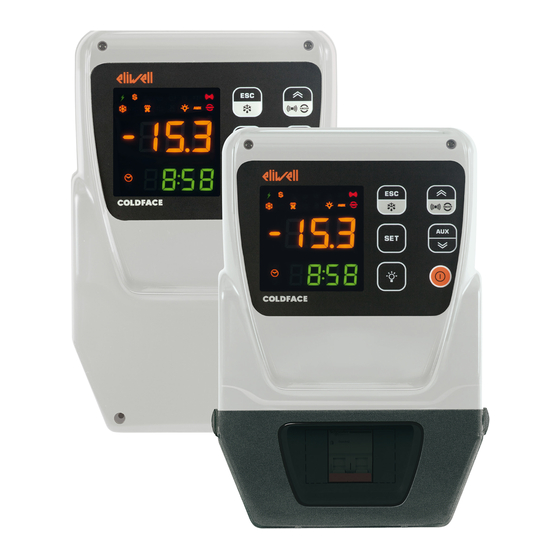
Eliwell EWRC 300 NT Quick Start Manual
Controllers for static and ventilated cold rooms
Hide thumbs
Also See for EWRC 300 NT:
- User manual (89 pages) ,
- Quick start manual (16 pages) ,
- User manual (107 pages)
Table of Contents
Advertisement
Quick Links
Advertisement
Table of Contents

Related Manuals for Eliwell EWRC 300 NT


Summary of Contents for Eliwell EWRC 300 NT
- Page 1 EWRC 300/500/5000 NT Controllers for static and ventilated cold rooms QUICK START...
- Page 2 The electrical panel (equipment) must be installed and repaired only by qualified staff. Eliwell accepts no responsibility for any consequences resulting from the use of this material. A qualified person is someone who has specific skills and knowledge regarding the structure and the operation of electrical equipment and who has received safety training on how to avoid the inherent dangers.
-
Page 3: Navigation Diagram
This summary document contains basic information about the standard EWRC 300/500/5000 NT models. For further information and different configurations, refer to the complete user manual cod. 9MA*0258 which is available to download free of charge from www.eliwell.com. NAVIGATION DIAGRAM Turns light... - Page 4 Drill the wall fixing holes on the back of the 343 / 13,5 panel, in the areas marked on the back. 171,5/ 6,75 mm / in 360 / 14,17 Fix the back of the panel to the wall using four screws (not supplied) suited to the wall thickness. NOTE: apply TDI20 screw caps (not provided) on 300/500 models.
-
Page 5: Electrical Connections
DANGER RISK OF ELECTRIC SHOCK, EXPLOSION OR EXPOSURE TO ACCESSIBLE PARTS The final application must disallow access to parts at hazardous voltage, as the instrument offers no intrinsic protection against this risk. Failure to follow these instructions will resultin death or serious injury. DIN rail-mounted models with window only. - Page 6 EWRC 300/500/5000 NT Yellow cable UNICARD COPY CARD DISPLAY RS485 OPTIONAL EWRC 500NT/ 5000 NT only ELIWELL ELIWELL OUT1 OUT2 OUT3 OUT4 OUT5 20 21 PB1 PB2 DI2 DI1 230 Vac PB3/DI3 MODELS WITH DOOR AND INTERNAL CIRCUIT BREAKER EWRC 500 NT BREAKER | EWRC 500 NT 4-DIN...
- Page 7 For EWRC NT 500 models with plastic knockout removed and no thermal-magnetic breaker installed: the end user is responsible for ensuring that open parts of the box cannot be accessed. DANGER RISK OF ELECTRIC SHOCK, EXPLOSION OR EXPOSURE TO ACCESSIBLE PARTS Prevent access to parts at hazardous voltages, as the instrument offers no protection against this risk.
- Page 8 colour description amber not used TIME amber access in case of time display or editing DATA amber access in case of date display or editing ALARMS Alarms LED 7 LED 8 Colour Buzzer Buzzer ALARM See “ALARMS TABLE” page 13 PANIC LEAK DETECTOR PANIC + LEAK DETECTOR...
-
Page 9: User Interface
USER INTERFACE How to modify the SetPoint • Press and release the SET key. The upper display will show SEt, the lower display will indicate the current SetPoint value • Press and release the SET key once more. The upper display will show SEt blinking •... - Page 10 PAR. DESCRIPTION M.U. RANGE DEFAULT Delayed start. The parameter indicates that a protection is active on the general compressor relay actuations. At least the indicated time must elapse between the request and the actual activation of the 0 ... 255 compressor relay.
- Page 11 PAR. DESCRIPTION M.U. RANGE DEFAULT dAO Temperature alarm exclusion time after defrost. 0 ... 250 Delay preceding temperature alarm signal. 0 ... 250 This parameter refers to high/low temperature alarms LAL and HAL only. DISPLAY parameters (diS) LOCk. Setpoint edit lock. The parameter programming menu can still be accessed, and the settings changed, which means also that the status of this parameter can be changed so as to unlock the keypad.
-
Page 12: Operation In Default Configuration
OPERATION IN DEFAULT CONFIGURATION The instrument is configured for negative cold. For positive cold, disable the evaporator probe Pb2 (set H42=n) and set relay OUT3 (parameter H23=6) to prevent continuous ventilation. COMPRESSOR The compressor is active if the cold room temperature measured by Pb1 exceeds the value of SEt + differential diF. -
Page 13: Alarms And Troubleshooting
FOR MORE INFORMATION READ the manual, code 9MA*0258 ALARMS TABLE This section lists alarms associated with the default configuration of the instrument. For a description of alarms relating to custom configurations, refer to the user manual or contact Eliwell Technical Support. Label Cause Effects Problem solving •... - Page 14 This section lists alarms associated with the default configuration of the instrument. For a description of alarms relating to custom configurations, refer to the user manual or contact Eliwell Technical Support. Label Cause Effects Problem solving End of defrost cycle due to time- out rather than due to defrost end •...
-
Page 15: Electrical Specifications
DESCRIPTION EWRC 500 BREAKER Circuit breaker Two-pole (2P) ELECTRICAL SPECIFICATIONS DESCRIPTION Rated voltage (Un) 230 Vac Rated operating voltage (Ue) 230 Vac Rated insulation voltage (Ui) 230 Vac Conditioned short circuit current (Icc) < 4.5 kA Rated frequency (fn): 50/60 Hz EWRC 500 BREAKER: Rated impulse withstand voltage (Uimp) 4 kV... -
Page 16: Liability And Residual Risks
- application: air - climate range A - measurement class 1 in the range -25 °C to 15 °C (-13 °F to 59 °F) (only when using Eliwell probes) Permitted use This equipment is used to control cold rooms in commercial refrigeration sectors.
Need help?
Do you have a question about the EWRC 300 NT and is the answer not in the manual?
Questions and answers