
Related Manuals for Eliwell ECH 200BD "Adaptive"


Summary of Contents for Eliwell ECH 200BD "Adaptive"
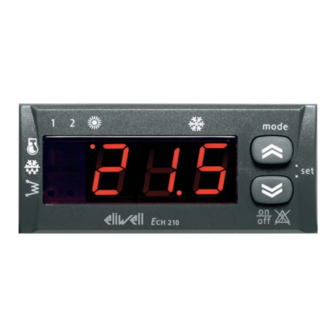
- Page 1 ECH 200BD "Adaptive" Electronic Controller for mono and bi- compressor Chillers with Adaptive Algorithm <IMG INFO> 396,8...
-
Page 2: Table Of Contents
SUMMARY Summary................................... 2 How to use this manual ............................5 Introduction ................................6 Models available....................................6 Installation ................................8 Connection diagrams ..................................8 Configuration of analogue inputs ..............................9 Configuration of digital inputs..............................10 Configuration of outputs ................................10 4.4.1 Relays................................................... - Page 3 Dynamic set point ..................................31 Switching from digital input ................................ 33 Load control..................................... 33 8.5.1 Compressor control – regulation algorithm....................................33 8.5.2 Condensation fan control ..........................................34 8.5.3 Reversing valve control ........................................... 36 8.5.4 Hydraulic pump control..........................................36 8.5.5 Anti-freeze/supplementary electrical heater control ................................
- Page 4 18.2 Copy Card......................................72 18.3 filter......................................72 18.4 Param Manager....................................72 18.4.1 PCInterface interface module ........................................73 18.5 Sonde......................................... 73 ECH 200 BD 4/76...
-
Page 5: How To Use This Manual
HOW TO USE THIS MANUAL This manual is designed to permit quick, easy reference with the following features: References column: References A column to the left of the text contains references to subjects discussed in the text to help you locate the information you need quickly and easily. -
Page 6: Introduction
INTRODUCTION Ech 200 is a compact device that permits control of air conditioning units of the following types: air-air • air-water • • water-water condensing units • single-circuit, with 1 or 2 compressors (steps). It is possible to control condensation fan speed proportionately for currents of up to 2 A without using external devices. - Page 7 Model ECH 210 BD ECH 215 BD Base parameters Circuits tabel Compressors (in chiller) Application Compressors (in heat pump) Stages Relays (2A 230 V~) Triac (2A 230 V~) Input/output Digital input Analog output Analog input Srew connectors • • Remote keyboard •...
-
Page 8: Installation
INSTALLATION Before proceeding with any operation, first make sure that you have connected up the power supply to the device through an appropriate external current transformer. Always follow these rules when connecting boards to one another and to the application: Never apply loads which exceed the limits set forth in these specifications to outputs;... -
Page 9: Configuration Of Analogue Inputs
Connection to probe AI3 configured as 4..20mA C 12AC GND AI4 12AC 12DC TC Line alarm output E: relay 1 B: LC filter F: relay 2 C: CF control G: relay 3 D: TK/relay 5 (only for 215 BD) H: relay 4 Instrument configuration is determined by the values of the parameters associated with inputs and outputs. -
Page 10: Configuration Of Digital Inputs
If input AI3 is defined as a 4...20 mA input, the scale bottom value of the pressure input is also signfiicant: H09, maximum input value; sets the corresponding value to a current of 20 mA Configuration of digital inputs There are 5 voltage-free digital inputs, which will henceforth be identified as ID1…ID5. -
Page 11: Relays
Labels 12~ ALL GND GND IA3 IA2 IA1 SERIAL KEYB 12~ 12= ID3 ID2 ID1 RELAYS 2(2)A 250V~ TRIAC(TK) 2A 250V~ NO1 NO2 NO3 NO4 <IMG INFO> Model Ech 210 BD 12~ ALL GND GND IA3 IA2 IA1 SERIAL KEYB 12~ 12= ID3 ID2 ID1 RELAYS 2(2)A 250V~... -
Page 12: Alarm
4.4.3 Alarm ALL - 12-24 V~ output for alarm, maximum current 500 mA. For models Ech 2xx BD the following parameters are available: Pa H56 = determines the polarity of the alarm output: • 0 = output is active (closed contact) when an alarm is active and when the machine is switched off. -
Page 13: Physical Quantities And Units Of Measurement
REMOTE KEYBOARD 24 25 26 REAR VIEW SERIAL KEYB CONN A CONN B <IMG INFO> REMOTE KEYBOARD: Remote keyboard REAR VIEW: Rear view 24: blue 25: white 26: black Physical quantities and units of measurement 4.5.1 Temperature- or pressure-based operation Parameter Pa H49 may be used to select two different types of machine: operated on the basis of temperature or of... -
Page 14: Serial Outputs
Eliwell interface module • • channel for serial communication with a standard Eliwell keyboard. Power supply 12 VDC (2400, e, 8, 1). 4.6.1 Copy card device Copy Card is a device that, if connected to the TTL serial port, allows to quickly program the instrument parameters. -
Page 15: User Interface
USER INTERFACE The interface on the front panel of the instrument can be used to carry out all the operations connected to the use of the instrument, and in particular to: Set operating mode • • Respond to alarm situations Keyboard IMG INFO •... -
Page 16: Led
5.2.3 compressor 1. • ON if compressor 1 is active OFF if compressor 1 is off • BLINK safety timing is in progress • Compressor 2 (or capacity step) ON if compressor (capacity step) is on • • OFF if compressor (capacity step) is off BLINK safety timing is in progress... - Page 17 REMOTE KEYBOARD 24 25 26 REAR VIEW SERIAL KEYB CONN A CONN B <IMG INFO> REMOTE KEYBOARD: Remote keyboard REAR VIEW: rear view of the control module ECH 200 BD 17/76...
-
Page 18: Parameter Programming - Menu Levels
The terminals of the remote keyboard are associated with the following colours: blue • • black • Be cautious when connecting these terminals because they are reversed against the connector’s terminals. Parameter programming – Menu levels Device parameters may be modified using a Personal Computer (with the required software, interface module and cables), or using the keyboard. - Page 19 The structure is set up as shown in the diagram below: Menu structure Level 0 Level 1 Level 2 Level 3 Level 4 Control Probe Set point Label Set Cooling Set Cooling Value Current Alarm Label Set Heating Set Heating Value Analogue Inputs Input Code t01...t04...
-
Page 20: Visibility Of Parameters And Sub-Menus
5.4.1 Visibility of parameters and sub-menus With a personal computer, interface key (copy card), suitable cables and the “Param Manager” software, it is possible to restrict the visibility and modification of parameters and entire submenus. A “visibility value” may be assigned to each parameter, as described below: Label Value Meaning... -
Page 21: System Configuration
SYSTEM CONFIGURATION In this section we will look at how to configure parameters for various loads on the basis of the type of installation to be controlled. Compressors Ech 200 BD can control systems consisting of one cooling circuit with 1 or 2 compressors. If there is a capacity step, it will be considered as a compressor. -
Page 22: Condensation Fan
If the system includes 2 compressors (or capacity steps) there are intervals of time which must pass between turning on of On-on and off-off Timing the 2 compressors (Pa C06) and turning off of the 2 compressors (Pa C07). An amount of time determined by parameter diagram for 2 Pa D11 (compressor on delay during defrosting) must pass between turning on a compressor and a capacity step. -
Page 23: Drv Module
Every time the external fan is started up, power is supplied to the exchanger fan at maximum voltage, and the fan operates Pick-up at maximum speed, for an amount of time equal to Pa F02 seconds; after this time the fan operates at the speed set by the regulator. -
Page 24: Internal Anti-Freeze/Supplementary Electrical Heaters
OPERATION IN RESPONSE TO REQUEST: Operation in The pump comes on in response to a request from the regulation algorithm. • response to The compressor comes on following a delay P02) after the time the pump comes on. • request •... -
Page 25: Supplementary Electrical Heaters
Pa r03 Heating mode configuration off during heating On during heating (depending on anti-freeze electrical heater control) Pa r04 Configuration of electrical heater control controlled on the basis of AI1 Controlled on the basis of AI2 probe in heating mode (refer to connection diagrams) -
Page 26: Adaptive
ADAPTIVE ECH 200BD is a special model of the ECH 200 line that features extremely versatile characteristics and features, particularly suited for small plants. These are: • Adaptive function Fan control in Defrosting mode • Antifreeze function with heat pump, depending on water pump and heat pump. Adaptive function Chillers are generally equipped with water accumulation tanks. -
Page 27: Set Point Regression (For Et≥Mt)
Examples: set+Int SET 1 SET 2 Comp. IMG INFO Cycle 0: Cooling Mode • point: SET(COO) Hysteresis: SET(COO) + C03 • Cycle 1: • Set point for cycle 1: SET(1) = SET (COO) – AO(1) Hysteresis for cycle 1: SET(1) + C03 + AO(1) = SET(COO) - AO(1) + C03 + AO(1) = SET(COO) + C03 •... -
Page 28: Protection In Cooling Mode
Set+Ist set ef f ettiv o C omp. O FF 7.1.4 Protection in Cooling mode If the output temperature is AI2 < C09 during a generic cycle n, the controller performs the following operations: Switches the compressor(s) off. • This adjustment can be considered a pre-threshold of the anti-freeze alarm (the cycle ends without generating alarms) if adaptive function... -
Page 29: Fan Control In Defrosting Mode
SET(1) = SET(COO) – AO(1) = 12 –1.7 = 10.3 Fan control in Defrosting mode During the defrosting phase, the condensing pressure may sometimes reach alarm levels before the heat exchanger has defrosted all the ice. To prevent this condition from tripping the high pressure alarm, the unit starts fans at minimum speed if the pressure/temperature read by probe AI3 is above value F22. -
Page 30: Temperature Control Functions
TEMPERATURE CONTROL FUNCTIONS Once Ech 200 has been configured, loads may be controlled on the basis of temperature and pressure conditions detected by probes and temperature control functions which may be defined using the appropriate parameters. There are 4 possible operating modes: Operating modes... -
Page 31: Setting Set Points
Mode Pa H29 Cooling Heating Ext Temp Pa H30 H29: Heating mode set point H30: Mode selection differential Ext temp: outdoor temperature Mode may be changed from the keyboard for temperatures which fall within the mode selection differential (determined by parameter H30). If this is not done: •... - Page 32 Positive Offset (H32>0 or H33>0) Modification depending on Offset current input with positive offset Max offset 4 mA 20 mA I: current Negative Offset (H32<0 or H33<0) Modification depending on Offset current input with negative offset 4 mA 20 mA Max offset I: current Modification...
-
Page 33: Switching From Digital Input
Negative Offset Modification depending on Pa H34 (cooling) o Pa H35 (heating) outdoor temperature with negative offset Tem p Delta < 0 Delta > 0 IMG INFO H34: outdoor temperature set point during cooling H35: outdoor temperature set point during heating Ext Temp: outdoor temperature Switching from digital input... -
Page 34: Condensation Fan Control
H05= 3, the compressor will be turned off and on depending on the status of input AI1. H06= 2, the compressor will be turned off and on depending on the status of input AI2. If a digital input is configured as a second step request (H18 or H19 or H20 or H21= 6), the response will depend on this input. - Page 35 The fan control unit may have a minimum speed, a maximum speed, and a “silent” speed (for silent operation, for instance Silent speed during the night), as well as a proportional band within these values. The fan will always be off if: •...
-
Page 36: Reversing Valve Control
Outdoor fan in HEAT mode Fan control in heat mode: Speed (%) Pa F20 diagram Pa F19 Pa F16 Pa F17 Pa F15 Pa F11 Temp/Press Pa F11 Pa F18 Pa F10 Speed: fan speed Temp: temperature Press: pressure Control is not active if: defrosting is in progress •... -
Page 37: External Anti-Freeze Electrical Heater Control
Diagram illustrating anti-freeze/supplementary electrical heater control Diagram Power Pa r07 (heating) o Pa r08 (cooling) Temp (IA1/IA2/IA3) Pa r11 IMG INFO Power: power Temp: temperature 8.5.6 External anti-freeze electrical heater control Control is based on probe AI3 with a set point which may be set using parameter Pa r12 and a... -
Page 38: Functions
FUNCTIONS Recording hours of operation The device stores the number of hours of operation of the following in permanent memory: hydraulic pump • compressors • It is precise to within one minute. Hours of operation may be displayed by entering the appropriate menu with the label Ohr (refer to menu... -
Page 39: Defrost End
If the machine is configured with 2 compressors, both compressors (steps) will be on during defrosting. This will not be the case if a thermal switch alarm has been given for one of the compressors. Compressor safety times are ignored during the defrost cycle. Start defrosting and end... -
Page 40: Power Failure
Temp: temperature Power failure In the event of a power failure, when the power is restored the control will return to the status it had before the power went out. defrosting is underway, it will be cancelled. All timing in progress when the power goes out will be cancelled and started again. -
Page 41: Diagnostics
DIAGNOSTICS “Ech 200” can perform full systems diagnostics and signal a series of alarms. Alarms Alarm trigger and reset modes are set using parameters Pa A01 – A26. For some alarms the signal will not be given for a certain amount of time, determined by a parameter. For some alarms the number of... - Page 42 CODE SIGNAL DESCRIPTION BLOCCO UTENZE BY PASS RESET Table of alarms COMPRESSOR 1 COMPRESSOR 2 EXTERNAL INTERNAL PUMP ELECTRICAL ELECTRICAL HEATER 1 HEATER 2 Remote Off Triggered by the digital input configured as “Remote ON-OFF ” (refer to digital inputs) High pressure Triggered by digital Always manually...
- Page 43 CODE SIGNAL DESCRIPTION BLOCCO UTENZE BY PASS RESET COMPRESSOR 1 COMPRESSOR 2 EXTERNAL INTERNAL PUMP ELECTRICAL ELECTRICAL HEATER 1 HEATER 2 manually reset; Probe AI2 fault Triggered if probe AI2, configured as an analogue input, shorts or is cut off or probe limits are exceeded (-50°C..
- Page 44 CODE SIGNAL DESCRIPTION BLOCCO UTENZE BY PASS RESET COMPRESSOR 1 COMPRESSOR 2 EXTERNAL INTERNAL PUMP ELECTRICAL ELECTRICAL HEATER 1 HEATER 2 AI4, configured as an analogue input, shorts or is cut off or probe limits are exceeded (-50°C.. 100°C). Anti-freeze alarm Active if probe AI3 is Goes off if...
-
Page 45: Table Of Digital Alarms
The tables below list alarms by type (digital or analogue). Digital alarms 10.1.1 TABLE OF DIGITAL ALARMS: Alarm name Bypass trigger event Bypass time Trigger Deactivation alarm duration duration events/hour High pressure alarm None absent absent absent Manual reset Low pressure alarm A compressor coming Pa A01... -
Page 46: Parameters
PARAMETERS Parameters make the ”Ech 200” a fully configurable device. They may be modified through: • instrument keyboard • copy card • personal computer (with a suitable connection and “Param manager” software) 11.1 Description of parameters We will now look at parameters in detail, divided by category. - Page 47 5= Compressor 2 thermal switch • • 6= Request for second compressor (step) Configuration of AI4 if configured as a digital input H08=2) Pa H21 0= Compressor thermal switch • • 1= Fan thermal switch 2= Flow switch • 3= Remote Heat/Cool •...
-
Page 48: Compressor Parameters (Cp)
2= 2 compressors (or 2 steps) • Enable pressure / temperature-based operation Pa H49 parameters Pa H07=0 (probe Al3 absent) and Pa F01 = 3 (functioning in response to request from • compressor) are forced. • temperature-based operation; parameters Pa H07,Pa F01 are forced to: H07= 1 (probe Al3 temperature), F01= 3 (functioning in response to request from compressor). -
Page 49: Alarm Parameters (All)
Minimum value of proportional fan control during cooling. Expressed as a percentage of the maximum permitted voltage, from 0 to 100%,. Maximum silent speed during cooling Pa F07 Maximum value of proportional fan control during cooling. Expressed as a percentage of the maximum permitted voltage, from 0 to 100%,. -
Page 50: Anti-Freeze/Boiler Parameters (Fro)
Not used Pa A14 Not used Pa A15 Not used Pa A16 Not used Pa A17 Not used Pa A18 Not used Pa A19 Machine out of coolant differential Pa A20 If the difference between the absolute value of Al2 and is lower than this parameter when in heating and higher when in cooling, the machine out of coolant timer will start. -
Page 51: Defrost Parameters (Dfr)
Boiler off differential Pa r14 Boiler off differential. If outdoor temperature exceeds Pa r14+Pa r13, the boiler will be turned off and the heat pump will be turned on. Supplementary electrical heater control Pa r15 If this parameter =1 the electrical heaters have the double function of anti-freeze electrical heaters and supplementary heaters Otherwise r15=0) the electrical heaters have only the anti-freeze function... - Page 52 Pa H28 Presence of heat pumpt 0 ÷ 1 Flag Pa H29 Heating mode set point 0 ÷ 255 °C Pa H30 Mode selection differential 0 ÷ 25.5 °C Pa H31 Enable dynamic set point 0 ÷ 1 Flag Pa H32 Dynamic set point offset in cooling mode...
- Page 53 Pa F20 Maximum fan speed temperature/pressure set point during -500 ÷ 800 °C/10–kPa*10 heating Pa F21 Internal fan step differential 0 ÷ 25.5 °C Pa F22 Internal fan step hysteresis 0 ÷ 25.5 °C Pa F23 Not used Pa F24 Not used Pa F25 Preventilation in...
- Page 54 Pa d05 Maximum defrost time 0 ÷ 255 Minutes Pa d06 Compressor-reversing valve wait time 0 ÷ 255 Seconds Pa d07 Drip time 0 ÷ 255 Seconds Pa d08 Temperature at which defrost starts if H49= 1 -50.0 ÷ 80.0 °C/10 Pa d09 Temperature at which...
-
Page 55: Technical Features
TECHNICAL FEATURES 12.1 Technical information Tipical Min. Max. Power supply tension 12V~ 10V~ 14V~ Power supply frequency 50Hz/60Hz Power Isolation class Use environment temperature 25°C -10°C 60°C Use environment humidity (non-condensing) Stocking environment temperature 25°C -20°C 85°C Stocking environment humidity (non-condensing) 12.2 Electromagnetic characteristic Digital exits 120/240 V... - Page 56 ECH 200 BD 56/76...
-
Page 57: Use Of The Device
USE OF THE DEVICE 13.1 Permitted use This product is used to control single circuit chillers and heat pumps. To ensure safety, the controller must be installed and operated in accordance with the instructions supplied, and access to high voltage components must be prevented under regular operating conditions. The device shall be properly protected against water and dust and shall be accessible by using a tool only. -
Page 58: Responsibility And Residual Risks
RESPONSIBILITY AND RESIDUAL RISKS Eliwell & Controlli srl. shall not be held liable for any damage incurred as a result of: installation/use other than those intended, and, in particular, failure to comply with the safety instructions specified • by applicable regulations and/or provided in this document;... -
Page 59: Disclaimer
DISCLAIMER This manual and its contents remain the sole property of Eliwell & Controlli s.r.l. and shall not be reproduced or distributed without authorization. Although great care has been exercised in the preparation of this document, Eliwell & Controlli s.r.l., its employees or its vendors, cannot accept any liability whatsoever connected with its use Eliwell &... -
Page 60: Examples Of Air Conditioning Circuits
EXAMPLES OF AIR CONDITIONING CIRCUITS The following chapter reports the main air-conditioning diagrams in their standard configuration. Obviously the manufacturer can decide to set the system in customed way. 16.1 Air-water chiller 1 compressor COND FS a ST a ST c TS a AFR a ST b... -
Page 61: Air-Water Chiller 2 Compressor
16.2 Air-water chiller 2 compressor COND FS a ST a ST c TS a AFR a ST b WP a TS b COMP a TS c COMP b HPS a LPS a <IMG INFO> SYMBOL ELEMENT CONNECTION COND condenser evaporator AFR a primary circuit anti-freeze resistance HPS a... -
Page 62: Water-Water Chiller 1 Compressor
16.3 Water-water Chiller 1 compressor HPS a LPS a TS a COMP a WP a ST b ST a COND AFR a AFR b ST c FS a SYMBOL ELEMENT CONNECTION COND condenser evaporator AFR a secondary circuit anti-freeze resistance NO5 (TK) AFR b primary circuit anti-freeze resistance... -
Page 63: Water-Water Chiller 2 Compressor
16.4 Water-water Chiller 2 compressor TS b COMP b HPS a LPS a TS a COMP a WP a ST b ST a COND AFR b AFR a ST c FS a IMG INFO SYMBOL ELEMENT CONNECTION COND condenser evaporator AFR a secondary circuit anti-freeze resistance NO5 (TK) -
Page 64: Air-Water Heat Pump 1 Compressor
16.5 Air-water heat pump 1 compressor ST a FS a TS a ST c COND AFR a ST b WP a TS b COMP a HPS a LPS a <IMG INFO> SYMBOL ELEMENT CONNECTION COND condenser evaporator AFR a primary circuit anti-freeze resistance HPS a high pressure switch LPS a... -
Page 65: Air-Water Heat Pump 2 Compressors
16.6 Air-water heat pump 2 compressors ST a FS a TS a ST c COND AFR a ST b WP a TS b COMP a TS c COMP b HPS a LPS a SYMBOL ELEMENT CONNECTION COND condenser evaporator AFR a primary circuit anti-freeze resistance HPS a high pressure switch... -
Page 66: Water-Water Heat Pump 1 Compressor
16.7 Water-water heat pump 1 compressor COND WP a AFR a ST b AFR b ST a ST c FS a TS a COMP a HPS a LPS a SYMBOL ELEMENT CONNECTION COND condenser evaporator AFR a secondary circuit anti-freeze resistance NO5 (TK) AFR b primary circuit anti-freeze resistance... -
Page 67: Water-Water Heat Pump 2 Compressors
16.8 Water-water heat pump 2 compressors COND WP a AFR a ST b AFR b ST a ST c FS a TS a COMP a TS b COMP b HPS a LPS a SYMBOL ELEMENT CONNECTION COND condenser evaporator AFR a secondary circuit anti-freeze resistance NO5 (TK) AFR b... -
Page 68: Glossary
GLOSSARY Multiple inputs with an OR relationship to one another are equivalent to a single input with the following status: Logical OR active, if at least one input is active; • Inactive if no input is active • “Scroll up” a menu means listing the various parameters from the bottom up (Pa08 ->... - Page 69 • panel drilling 29x71 mm; • integrated fan speed control up to 2A maximum without CF additional module. • MODBUS communication protocol • Antifreeze function with heat pump • Adaptive Function • Defrosting • The same as ECH 210BD except for: Ech 215 BD MW320040 5 internal...
-
Page 70: Cf Modules
18.1 CF Modules CF series instruments are optional modules that if connected to the main control systems allow the adjustment of fans with current from 2 A to 10 A. They have an “open board” form and are available in several models: •... -
Page 71: Cf Modules: Mechanical Assembly
Connection diagram (max 500 Watt) 32 31 30 29 28 27 26 25 24 23 22 21 N6 N5 CF-05 CF-REL 33 34 35 36 N4 N3 N2 N1 F4 F3 F2 F1 (max 1.500 Watt) (max 2.200 Watt) 32 31 30 29 28 27 26 25 24 23 22 21 N6 N5 32 31 30 29 28 27 26 25 24 23 22 21 N6 N5... - Page 72 Module dimensions fl 4.0 fl 4.0 CF-05 CF-15 CF-REL CF-22 72.0 85.0 85.0 90.0 90.0 <IMG INFO> 18.2 Copy Card Copy Card photo <IMG INFO> 226,7 119,3 99,25 212,25 111,75 This device is used to upload and download the device parameter map. copy Card <IMG INFO>...
-
Page 73: Pcinterface Interface Module
18.4.1 PCInterface interface module This device enables the controller to interface with the PC. For information on how to connect the device, see the Param Manager Manual. For information on the technical specifications of PCI2150, see the instruction sheet. PCI2150 The PC must be connected with the interface module, and the interface module with the device, with no power on to any of the devices, and in compliance with current safety regulations. - Page 74 ANALITIC INDEX On-on timing ..............21 4-20 mA or 0-10 V output..........12 Timing................22 Compressors..............21 Actual time..............26 Condensation fan ............22 ADAPTIVE ............... 26 Condensation fan control..........34 Adaptive function ............26 Cool mode..............35 regulator..............26 Heat mode..............35 Adaptive offsets .............. 26 Configuration of analogue inputs ........
- Page 75 Modification depending on current input with Led..................16 negative offset ............32 List of alarms ..............41 Modification depending on current input with Load control ..............33 positive offset ............32 Loads .................68 Modification depending on outdoor temperature Logical OR ................68 with negative offset..........33 Manual reset..............68 Modification depending on outdoor temperature...
- Page 76 Water-water heat pump 1 compressor .....66 SYSTEM CONFIGURATION........... 21 Water-water heat pump 2 compressors ....67 Eliwell & Controlli s.r.l. Via dell’Industria, 15 Zona Industriale Paludi 32010 Pieve d’Alpago (BL) ITALY Telephone +39 0437 986111 Facsimile +39 0437 989066 Internet http://www.eliwell.it...
Need help?
Do you have a question about the ECH 200BD "Adaptive" and is the answer not in the manual?
Questions and answers