Table of Contents
Advertisement
Quick Links
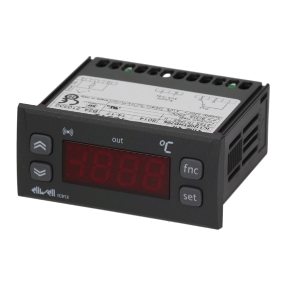
IC 912
Pt100 Tc / P R V-I I-V
single stage electronic controller
UP
KEYS
Scrolls through the menu items
Increases the values
Relay OUT
LEDs
ON for relay on (energized);blinking for
delay, protection or enabling blocked.
Press the 'set' button and release it to access the machine status
menu.
In normal conditions, the labels for the two Set point values are
found in the menu.
set
set
To access the Programming menu, hold the "set" button down
for more than 5 seconds.
set
At each level in both menus, when the "fnc" button is pressed or the 15 second time out elapses, you are taken back to the higher
Access to parameter handling can be limited by using a password.
The password can be enabled by setting the PA1 parameter in the
'diS' folder. The password is enabled if the value of the PA1 para-
meter is not 0.
set
The Copy Card is an accessory connected to the TTL serial port
used for quick programming of the unit parameters (upload and
download parameter map to one or more units of the same
type). Upload (UL label), download (dL label) and copy card for-
matting (Fr label) operations are performed in the following way:
set
set
set
set
DOWN
Scrolls through the menu items
Decreases the values
SETTING THE SET POINT - MACHINE STATUS MENU
set
PROGRAMMING MENU
• When the 'set' button is pressed, the
first folder in the menu is displayed.
(e.g.: "rE1" folder)
• By using the 'UP' and 'DOWN' buttons,
you can scroll through all the folders in
the programming menu
display level and the last value on the display is stored.
• To enter the Programming menu hold
the "set" button down for more than 5
seconds.
If specified, the PASSWORD will be
requested
• The 'FPr' folder contains the command
needed to use the Copy Card. Press 'set'
to access the functions.
• Use the 'UP' and 'DOWN' buttons to dis-
play the required function. Press the
'set' to perform uploading (or down-
loading).
• If the operation is successful 'y' will be
displayed, if it is not, 'n' will be dis-
played.
fnc
fnc
ESC function (quit)
Allarme
ON for active alarm; blinking for
silenced alarm
Once the 'SP1' label has been displayed, press the "set" button to
display the Set point 1 value.
The Set point value appears on the display. To change the Set
point value, use the "UP" and "DOWN" buttons within 15 sec-
onds.
If you press the "set" button again, when the fnc button is
pressed or 15 seconds elapse, the last value displayed will be
stored and the "SP1" label will reappear on the display.
set
set
pressed (or the 15 second time out elapses) the new value is
stored and the label of the corresponding parameter will be dis-
played.
PASSWORD
set
If the password is not entered correctly, the device will display
the 'PA1' label again and the step will have to be repeated.
COPY CARD
Download from reset
Connect the copy card when the instrument is OFF. The program-
ming parameters are downloaded when the device is switched
on. At the end of the lamp test, the following messages are dis-
played for about 5 seconds:
• dLY label if copy operation is successful
• DLn label if operation fails
NOTE:
• After downloading, the instrument will work with the parame-
ter map settings that have just been downloaded.
• see "FPr folder" in Parameter Table and Description of parame-
ters
set
set
Accesses the Set point and the Menus
Confirms the commands
At start-up the instrument performs a Lamp Test for 5
seconds. Afterwards, only for IC 912 Pt100, the label 'Lod'
(Loading) will appear for 10 seconds.
• By pressing the "set" button for the
selected folder (in this example, 'CnF')
the first parameter is displayed. Use
the "UP" and "DOWN" buttons to
select the required parameter.
• Press "set" to display the selected para-
meter value and use the "UP" and
"DOWN" buttons to change it.
Once the "set" button has been
• If the PA1 password is enabled (not 0)
you will be asked to enter it. Do this by
selecting the correct value using the UP
and DOWN buttons and confirm by
pressing the 'set' button.
DOWNLOAD
UPLOAD
Advertisement
Table of Contents

Related Manuals for Eliwell IC 912 Series


Summary of Contents for Eliwell IC 912 Series
- Page 1 IC 912 Pt100 Tc / P R V-I I-V single stage electronic controller DOWN KEYS Scrolls through the menu items Scrolls through the menu items ESC function (quit) Accesses the Set point and the Menus Increases the values Decreases the values Confirms the commands Relay OUT Allarme...
- Page 2 ALARMS Label Alarm Cause Effects Resolving problems Probe 1(control) • measuring of values outside the nominal reading “E1” label appears on display; • check the probe wiring range Controller enabled as indicated by the On1 and faulty • replace the probe •...
- Page 3 TECHNICAL DATA IC 912 P/R/V-I/I-V IC 912 Pt100/TC Front protection IP65 IP65 Casing resin plastic casing PC+ABS UL94 V-0, polycarbonate resin plastic casing PC+ABS UL94 V-0, polycarbonate front polycarbonate front, thermoplastic resin buttons front polycarbonate front, thermoplastic resin buttons front panel 74x32 mm, depth 59mm (terminals excluded) front panel 74x32 mm, depth 59mm (terminals excluded)a Dimensions panel-mounted with drilling template 71x29mm (+0.2/-0.1 mm)
- Page 4 The same applies to any person or company involved in preparing and shock, water or dust when assembled; writing this document. Eliwell reserves the right to make any changes or - use on boards which allow dangerous parts to be accessed without the use improvements without prior notice and at any time.
Need help?
Do you have a question about the IC 912 Series and is the answer not in the manual?
Questions and answers