Advertisement
EWDR 983-985/CS (LX)
EWDR 985/CSK (LX)
electronic controllers for ventilated refrigeration units
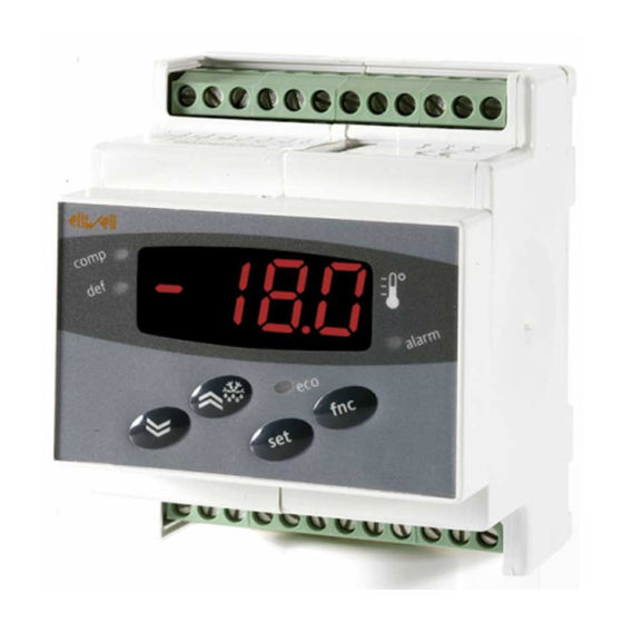
USER INTERFACE
The user interface has a 6 LED display to
indicate alarm status and five buttons for
controlling instrument status and pro-
gramming.
BUTTONS AND LEDS
UP
Increase in value of
parameter Menu scrolling
and activation of defrost
function
(Parameter programmable
H31)
DOWN
Decrease in value of
parameter
Menu scrolling and activation
of associated function
(Parameter programmable
H32)
set
Access to different levels of
menu Alarm display, set
point, probes and rtc
Access to programming of
parameters
fnc
Exit current level of
menu Confirmation of value of
parameter
(Parameter programmable
H33)
aux
Activation of associated
function using parameter
H34
LED
Description
Indication
Reduced set point
Lights up when
inserted LED
set point is
displayed*, blinking
* EWDR983/985 /CS (LX) only
when reduced set
point is inserted
LED
'on' with compressor
LED on. Blinking
for delay, protection
or activation blocked
defrost LED
'on' during defrosting
Blinking when
activated manually
or by digital input
fan LED
permanently on when
fans are operating
alarm LED
'on' if alarm is present.
Blinking for silenced
alarm
auxiliary LED
'on' for active output
decimal point
'on' to indicate of
voltage when on
stand-by and display
'off'
SIGNAL LED
The status of the external devices, func-
tions and controllers is described by the
device LEDs.
DISPLAY
This is used to display the inputs, the set
point, the parameters and related values,
alarms, functions and the status of the
device.
DESCRIPTION OF MENU
Access to both menus is controlled by
the 'set' button. If it is pressed and
immediately released, the 'machine sta-
tus menu' is displayed. Hold the same
button down for 5 seconds to access the
'parameter programming menu'.
When one of the two menus has been
accessed, you can navigate between the
level 1 folders using the 'UP' and 'DOWN'
buttons. The folders are opened by
pressing the 'set' button once. You can
now scroll through the contents of each
folder, modify it or use its functions.
You can exit each level of both menus in
three ways: using the 'fnc' button, if a
new value is confirmed by pressing the
'set' button or, when the time-out has
elapsed (15 seconds inactivity on the
device).
MACHINE STATUS MENU
The 'machine status menu' contains the
folders and basic information on the
device:
-AL: alarm folder
-SEt: Set point setting folder
-rtc: Real Time Clock folder(if present)
-Pb1: 'probe 1 value' folder
-Pb2: 'probe 2 value' folder
-Pb3: 'probe 3 value' folder
If no alarms are present, the "SEt" label
is displayed. From here, you can scroll
down the other menu items using the
UP' and 'DOWN' buttons. Each folder
can be accessed by pressing the 'set'
button once.
Values are modified using the 'UP' and
'DOWN' buttons and the 'set' button
that confirms the selected value and
takes you back to the higher level.
Setting the set point
Access the 'machine status menu'. If no
alarms are present, the "SEt" label is dis-
played. By pressing and immediately
releasing the 'set' button, the set point
value can be set using the UP' and
'DOWN' buttons. Press and release the
'set' button again or press the 'fnc' but-
ton to go back to the main menu level.
The set point setting folder is also closed
when the time-out elapses.
Alarm on
If an alarm condition exists when the
Machine Status menu is accessed the
"ALfolder label appears.
Real Time Clock (/C models)
By pressing the "set" button when the
"rtc" label appears, the label d00 (days)
is displayed. Use the "UP" and "DOWN"
buttons to set days. If you do not use
the buttons for over 2 seconds or if you
press "set" you switch to the hours (h00)
and minutes ('00) folders: use the "UP"
and "DOWN" buttons to set the hours
and minutes respectively. If you do not
use the keyboard for over 15 seconds
(time-out) or if you press the "fnc" but-
ton once, the last value shown on the
display is confirmed and you go back to
the previous screen mask.
NOTE: Always use the "set" button to
confirm the hours/minutes/days set-
ting.
NOTE2: We recommend considering
the first day d00 as SUNDAY.
PARAMETER PROGRAMMING MENU
Access the menu by pressing the 'set'
button for at least 5 seconds. The menu
structure enables all parameter folders
to be divided into two levels. All the
level 1 folders can be accessed by enter-
ing the password 'PA1'.
Scroll down the level 1 folders using the
'UP' and 'DOWN' buttons. Press and
release the 'set' button next to the
selected label to access the parameters.
Scroll through the labels in the folder
using the 'UP' and 'DOWN' buttons,
press 'set' to display the current value of
the selected parameter, use the 'UP' and
'DOWN' buttons and set the required
value by pressing 'set'. To access the
level 2 folders in the 'Cnf' folder, select
the 'PA2' label, enter the password 'PA2'
and confirm with the 'set' button. All the
parameters that cannot be changed at
level 1 are in this level.
NOTE: Level 1 parameters will only be
displayed if you quit the 'parameter
programming menu' and repeat the
steps for manipulation of level 1 folders.
The steps to follow for manipulation of
level 2 parameters are the same as those
described for the level 1 structure.
N N O O T T E E : It is strongly recommended
that the instrument is switched off
and on again each time parameter
Advertisement
Table of Contents

Related Manuals for Eliwell EWDR 983/CS


Summary of Contents for Eliwell EWDR 983/CS
- Page 1 EWDR 983-985/CS (LX) EWDR 985/CSK (LX) electronic controllers for ventilated refrigeration units USER INTERFACE SIGNAL LED The set point setting folder is also closed The status of the external devices, func- when the time-out elapses. The user interface has a 6 LED display to tions and controllers is described by the Alarm on indicate alarm status and five buttons for...
-
Page 2: Advanced Functions
configuration is changed in order to REMOTE CONTROL SYSTEMS The configuration of these parameters prevent malfunctioning of the config- (/CS LX - /CSK LX models only) controls the status of the light relay by uration and/or ongoing timings. Televis remote control systems can be using the digital input as well as the nor- connected using the RS 485 serial input. -
Page 3: Mechanical Assembly
EXTERNAL ALARM MINIMUM AND MAXIMUM TEMPERA- per terminal block for power It is set if the digital input is enabled TURE ALARM connections): for terminal capacity, see with the delay specified by parameter If an alarm condition occurs and alarm the label on the instrument. - Page 4 PAR. DESCRIPTION RANGE DEFAULT VALUE LEVEL U.M. Set point with range falling between the minimum LSE...HSE °C/°F LSE set point and the maximum HSE set point. The value of the set point is in the machine status menu When the compressor stops when it reaches the 0.1...30.0 °C/°F set point value, it restarts at a value corresponding...
- Page 5 PAR. DESCRIPTION RANGE DEFAULT VALUE* LEVEL** U.M. End of defrost temperature (determined by evapo- -50.0...150 °C/°F rator probe) End of defrost temperature (determined from -50.0...150 °C/°F probe on 2nd evaporator) Determines when instrument starts up if the flag defrosting cycle must be activated (if the tempera- ture on the evaporator allows this) y=defrosting activated at start-up n=defrosting not activated at start-up...
- Page 6 PAR. DESCRIPTION RANGE DEFAULT VALUE* LEVEL** U.M. High and low temperature alarm delay after dis- 0...10 hours abling digital input (door closed) Time out after alarm signal when digital input is 0...250 disabled (door open) tAO (5) Temperature alarm delay time 0...250 Alarm for defrosting ended due to time out.
- Page 7 PAR. DESCRIPTION RANGE DEFAULT VALUE* LEVEL** U.M. Keyboard locked. Parameters can still be pro- flag grammed. n= keyboard not locked y= keyboard locked Contains the password for level 1 parameters. 0...250 Enabled if not 0 Contains the password for level 2 parameters. 0...250 Enabled if not 0 Display with decimal point.
- Page 8 PAR. DESCRIPTION RANGE DEFAULT VALUE* LEVEL** U.M. H12 (8) Configuration of digital inputs/polarity -8...8 Same as H11 Digital output configurability: 0= disabled 1= compressor 2= defrosting 3 = fans 4 = alarm 5= auxiliary 6= stand-by 7= light 8= buzzer 9 = defrosting on 2nd evaporator EWDR 983 H21 Digital output configurability C...
-
Page 9: Machine Status Menu
DISCLAIMER Eliwell shall not be liable for any damages deriving from: This document is the exclusive property of Eliwell and cannot be repro- - installation/use other than that prescribed and, in particular, which does duced and circulated unless expressly authorized by Eliwell. -
Page 10: Programming Menu
PROGRAMMING MENU press for 5 sec PA10 set PA1 value level 1 par level 2 par level 1 par level 2 par level 1 par level 2 par level 2 par level 1 par scroll parameters change par value level 2 par level 1 par 985/CSK level 2 par... - Page 11 Sales +39 0437 986 100 (Italy) • +39 0437 986 200 (other countries) • E-mail saleseliwell@invensyscontrols.com Technical helpline +39 0437 986 300 • E-mail techsuppeliwell@invensyscontrols.com www.eliwell.it © Eliwell Controls s.r.l. 2008 All rights reserved. cod. 9IS43068 - GB - rel. 3/08...
- Page 12 WIRING DIAGRAM EWDR 985/CSK (LX) - LINK TERMINALS Probe input 1 (room probe) Probe input 2 (evaporator probe) Probe input 3 (display or 2nd evaporator probe) RS 485 LINK Digital input 1 - GND Digital input 2 Link (8= +; 9= -) 1 2 3 4 5 6 7 8 9 10 11 12 10-12...
Need help?
Do you have a question about the EWDR 983/CS and is the answer not in the manual?
Questions and answers