Table of Contents
Advertisement
cod. 9IS44048
GB
rel. 4/06
USER INTERFACE
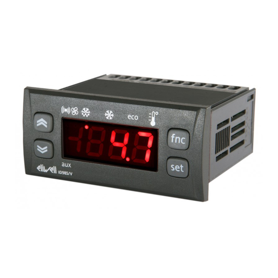
The user has a display and four buttons
for controlling instrument status and pro-
gramming.
At start-up the instrument performs a
Lamp Test; the display and LEDs flash for a
few seconds to check that they are work-
ing correctly. The instrument has two main
menus: the Machine Status menu and the
Programming menu.
ACCESSING AND USING MENUS
The resources are arranged in a menu that
can be accessed by pressing and quickly
releasing the "set" button (Machine Status
menu) or holding down the "set" button
for more than 5 seconds (Programming
menu). To access the contents of each
folder indicated by the relevant label, just
press the "set" button once.
You can now scroll through the contents
of each folder, modify it or use its func-
tions.
If you do not use the keyboard for over 15
seconds (time-out) or if you press the
"fnc" button once, the last value shown on
the display is confirmed and you are taken
back to the previous screen mask.
UP button
Scrolls through the menu items
Increases values
Activates manual defrosting
(see H31 parameter)
DOWN button
Scrolls through the menu items
Decreases the values
Parameter programmable
(see H32 parameter)
Position
Associated function
Set point/Reduced set point ON for parameter programming level 2
Compressor or relay 1
Defrosting
Alarm
Fans
aux
aux
ID 985
electronic controllers for "ventilated" refrigeration units
MACHINE STATUS MENU
(See Machine Status Menu Diagram)
To access the Machine Status menu, press
the "set" button and quickly release it.
If no alarms are present, the label "SEt"
appears. By using the "UP" and "DOWN"
buttons you can scroll through the other
folders in the menu:
-AL: alarm folder (if alarms present, except
for faulty probes/probe errors and COH);
-SEt: Set point setting folder.
-Pb1: probe 1 value folder;
-Pb2: probe 2 value folder;
-Pb3: probe 3 value folder (if present);
Set setting
Access the "Machine Status" menu, press
the "set" button and quickly release it. The
"Set" folder label appears. To display the
Set point value, press the "set" button
again.
The Set point value appears on the display.
To change the Set point value, use the
"UP" and "DOWN" buttons within 15 sec-
onds. If the parameter is LOC = y the Set
point cannot be changed.
BUTTONS AND DISPLAY
aux
ID985
LEDs
Status
blinking when reduced set point is entered
(set point ON for setting set point)
ON for compressor on; blinking
for protection delay or enabling blocked
ON when defrosting in progress; blinking when activated
manually or by digital input
ON for active alarm; blinking for silenced alarm
ON when fan is on
ON when auxiliary output is operating
Alarm on
If an alarm condition exists when the
Machine Status menu is accessed the "AL"
folder label appears (see section on
"Diagnostics").
NOTE: Always use the "set" button to
confirm the hours/minutes/days setting.
NOTE2: We recommend considering the
first day d00 as SUNDAY.
PROGRAMMING MENU
(See Programming Menu Diagram)
1) Displaying level 1 parameters
To access the Programming menu, hold
the "set" button for more than 5 seconds.
If specified, the level 1 access PASSWORD
will be requested (see parameter "PA1")
and (if the password is correct) the label
of the first folder will appear. If the pass-
word is incorrect, the display will show the
PA1 label again.
When the instrument is on stand-by, para-
meter programming can be accessed with
the display both on and off.
Use the "UP" and "DOWN" buttons to
scroll through the other folders; the fold-
ers will only display level 1 parameters.
NOTE: at this point level 2 parameters
are NOT visible even if NOT password-
protected.
fnc button
ESC function (quit)
fnc
Parameter programmable
(see H33 parameter
fnc
set
Set button
Accesses Set point
set
Accesses the Menus
Confirms the commands
Displays the alarms (if active)
Stores hours/min
2) Displaying level 2 parameters
Go to the "CnF" folder in the
Programming Menu and scroll down the
parameters until you reach the PA2 label.
By pressing and releasing the "set" button
you will enter the level 2 parameters and
the label of the first folder in the pro-
gramming menu will appear.
Level 2 parameters can be protected by a
second password (see "PA2" parameter in
"diS" folder, not to be confused with PA2
label in the "CnF" folder). If specified, level
2 parameters are hidden from the user;
when accessing the "CnF" folder the level
2 access PASSWORD will be requested and
(if the correct password is entered) the
Advertisement
Table of Contents

Subscribe to Our Youtube Channel
Related Manuals for Eliwell ID 985


Summary of Contents for Eliwell ID 985
- Page 1 ID 985 electronic controllers for “ventilated” refrigeration units cod. 9IS44048 rel. 4/06 USER INTERFACE MACHINE STATUS MENU Alarm on (See Machine Status Menu Diagram) If an alarm condition exists when the The user has a display and four buttons To access the Machine Status menu, press Machine Status menu is accessed the “AL”...
- Page 2 Start of defrosting consensus programming of the unit parameters If two evaporators are used, defrosting Digital output configurability/polarity 1 (upload and download parameter map to starts in three different ways that are H21...H25 Digital output configurability 1...5 ID 985 2/10...
- Page 3 This alarm condition can minimum pressure switch input switch be viewed in the “AL” folder with the input (number) labels “AH3-AL3”. Minimum/maximum pressure switch error count time (minutes) When you set parameter PbA=4, probe 3 ID 985 3/10...
- Page 4 TECHNICAL DATA is deactivated. OPEN DOOR ALARM ID 985 If a door is open, the Open Door alarm is Front protection: IP65. signalled in response to a delay defined by Casing: PC+ABS UL94 V-0 resin plastic the tdO parameter.
- Page 5 NOTE: At level 1 the folders will only display all the level 1 parameters. At level 2 the folders will only display all the level 2 parameters. The level marked 1-2 allows the parameter to be displayed at both levels. 5/10 ID 985...
- Page 6 NOTE: At level 1 the folders will only display all the level 1 parameters. At level 2 the folders will only display all the level 2 parameters. The level marked 1-2 allows the parameter to be displayed at both levels. ID 985 6/10...
- Page 7 NOTE: At level 1 the folders will only display all the level 1 parameters. At level 2 the folders will only display all the level 2 parameters. The level marked 1-2 allows the parameter to be displayed at both levels. ID 985 7/10...
- Page 8 NOTE: At level 1 the folders will only display all the level 1 parameters. At level 2 the folders will only display all the level 2 parameters. The level marked 1-2 allows the parameter to be displayed at both levels. ID 985 8/10...
- Page 9 1 par level 2 par PARAMETERS level 1 folders level 2 folders level 1 par level 2 par level 1 par level 2 par level 1 level 2 par level 2 par level 2 par level 2 ID 985 9/10...
- Page 10 N.O. relay output (A) see H22 (defrosting default) 12 - 14 N.C. relay output (A) see H22 (defrosting default) This document is the exclusive property of Eliwell Controls S.r.L. and cannot be 15 - 16 N.O. relay output (B) see H21 (compressor default) reproduced and circulated unless expressly authorized by Eliwell Controls S.r.L..
Need help?
Do you have a question about the ID 985 and is the answer not in the manual?
Questions and answers