Advertisement
Quick Links
cod. 9IS43022
GB
rel. 5/05
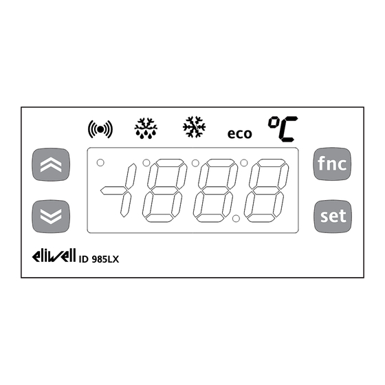
USER INTERFACE
The user has a display and four buttons
for controlling instrument status and pro-
gramming.
BUTTONS AND MENUS
UP Button
Scrolls through the menu items
Increases the values
Activates manual defrosting
(see H31 parameter)
DOWN
Scrolls through the menu items
button
Decreases the values
Parameter programmable
(see H32 parameter)
fnc button
ESC function (quit)
fnc
Parameter programmable
(see H33 parameter)
Set point button
Accesses the set point
Accesses the Menus
set
Confirms the commands
Displays the alarms (if active)
Stores hours/min
eco
ID 985LX
At start-up the instrument performs a
Lamp Test; the display and LEDs flash for a
few seconds to check that they are work-
ing correctly. The instrument has two main
menus: the Machine Status menu and the
Programming menu.
LEDS
Position
Associated function
eco
Set point/Reduced set point ON for parameter programming level 2
(set point
Compressor or relay 1
Defrosting
Alarm
Fans
aux
aux
o
decimal point
ID 983-985 LX (/C/CK) HACCP
electronic controllers for "ventilated" refrigerating units
ACCESSING AND USING MENUS
The resources are arranged in a menu that
can be accessed by pressing and quickly
releasing the "set" button (Machine Status
menu) or holding down the "set" button
for more than 5 seconds (Programming
menu).
To access the contents of each folder
indicated by the relevant label, just press
the "set" button once. You can now scroll
through the contents of each folder, mod-
ify it or use its functions. If you do not use
the keyboard for over 15 seconds (time-
out) or press the "fnc" button once, the
last value shown on the display is con-
firmed and you are taken back to the pre-
vious screen mask.
MACHINE STATUS MENU
(See Machine Status Menu Diagram)
To access the Machine Status menu, press
the "set" button and quickly release it. If
no alarms are present, the label "SEt"
appears.
By using the "UP" and "DOWN" buttons
f nc
you can scroll through the other folders in
the menu:
-AL: alarm folder (if alarms present, except
set
for faulty probes/probe errors;
-SEt: Setpoint setting folder.
-rtc (/C, /CK models): real time clock fold-
er;
-Pb1: probe 1 value folder;
-Pb2: probe 2 value folder;
-Pb3: probe 3 value folder (if present);
Set setting
Access the "Machine Status" menu, press
the "set" button and quickly release it. The
"Set" folder label appears.
Status
blinking when reduced set point is entered
(ON for setting set point)
ON for compressor on; blinking
for protection delay or enabling blocked
ON when defrosting in progress; blinking when activated
manually or by digital input
ON for active alarm; blinking for silenced alarm
ON when fan is on
ON when auxiliary output is operating
ON when instrument is on stand-by
To display the Set point value, press the
"set" button again.
The Set point value appears on the display.
To change the Set point value, use the
"UP" and "DOWN" buttons within 15 sec-
onds. If the parameter is LOC = y the Set
point cannot be changed.
Real Time Clock (/C /CK models)
By pressing the "set" button when the
"rtc" label appears, the label d00 (days) is
displayed.
Use the "UP" and "DOWN" buttons to set
days.
If you do not use the buttons for over 2
seconds or press "set", you switch to the
hours (h00) and minutes ('00) folders: use
the "UP" and "DOWN" buttons to set the
hours and minutes respectively. If you do
not use the keyboard for over 15 seconds
(time-out) or press the "fnc" button once,
the last value shown on the display is con-
firmed and you are taken back to the pre-
vious screen mask.
NOTE: Always use the "set" button to
confirm the hours/minutes/days set-
ting.
NOTE2: We recommend considering the
first day d00 as SUNDAY.
Alarm on
If an alarm condition exists when the
Machine Status menu is accessed the "AL"
folder label appears (see section on
"Diagnostics").
Displaying probes
If you press the "set" button when the
corresponding label appears, the value of
the probe associated with it is displayed.
PROGRAMMING MENU
(See Programming Menu Diagram)
1) Displaying level 1 parameters
To access the Programming menu, hold
the "set" button for more than 5 seconds.
If specified, the level 1 access PASSWORD
will be requested (see parameter "PA1")
and (if the password is correct) the label
of the first folder will appear. If the pass-
word is incorrect, the display will show the
PA1 label again.
Use the "UP" and "DOWN" buttons to
scroll through the other folders; the fold-
ers will only display level 1 parameters.
NOTE: at this point level 2 parameters
are NOT visible even if NOT password-
protected.
2) Displaying level 2 parameters
Go to the "CnF" folder in the
Programming Menu and scroll down the
parameters until you reach the PA2 label.
By pressing and releasing the "set" button
Advertisement


Need help?
Do you have a question about the ID 983LX HACCP and is the answer not in the manual?
Questions and answers