Table of Contents
Advertisement
Quick Links
Advertisement
Table of Contents

Related Manuals for Eliwell FREE Panel EVP 3300/C


Summary of Contents for Eliwell FREE Panel EVP 3300/C
- Page 1 Panel Panel Mount Programmable Controller Installation Manual...
-
Page 2: Table Of Contents
CONTENTS Introduction ................................3 General description ..................................3 1.1.1 Specifications: ..............................................4 Models and Features ..................................4 Mechanical Installation ............................5 Electrical connections ............................6 General warnings....................................6 3.1.1 Power supply ............................................... 6 3.1.2 Analogue Inputs-Probes........................................... 6 3.1.3 Serial connections.............................................. 6 Wiring diagrams.................................... -
Page 3: Introduction
General description The FREE Panel (EVP) is a fully programmable panel mounting solution with LCD display made by Eliwell, suitable for managing a wide range of HVAC/R and many other applications, from the simplest to the most complex. The EVP be used as a system controller, with gateway functions;... -
Page 4: Specifications
1.1.1 Specifications: FREE Panel EVP 3300/C is equipped with serial CAN, RS485 and ETHERNET, 3 inputs (1 on-board NTC + 1 remote configurable NTC/DI +1 remote current/voltage configurable). FREE Panel EVP 3500/C/R is equipped with serial CAN, RS485 and ETHERNET, 3 inputs (1 on-board humidity module + 1 on-board NTC + 1 remote configurable NTC/DI) . -
Page 5: Mechanical Installation
MECHANICAL INSTALLATION IMPORTANT! Always make sure the device is switched OFF before touching connections. All operations must be carried out by qualified personnel. Do not mount devices in extremely damp and/or dirt-laden areas; they are designed for use in places with ordinary or normal levels of contamination. -
Page 6: Electrical Connections
Pressure probes Signal leads (temperature/pressure probes, digital inputs, RS-485/CAN-BUS serials and the electronic supply) must be routed separately from power cables. Use probes supplied by Eliwell. Contact Eliwell sales department for parts availability. 3.1.3 Serial connections On-board as standard On-board... - Page 7 RS485 RS485 INSTALLING THE RS-485 NETWORK NOTE 1 Use a shielded and "twisted pair" cable with two 0.5mm conductors, plus braiding (ideally Belden cable model 8762 with PVC sleeve, 2 conductors plus braid, 20 AWG, nominal capacity between conductors 89pF/m, nominal capacity between conductor and shielding 161pF/m).
-
Page 8: Wiring Diagrams
Wiring diagrams EVP3300/C CAN: max distance depending on baud rate POWER WARNING RS485 WHILE CABLING POWER RS485 FREE EVOLUTION Remote Probes EVD ● EVC 24 Va/c 48 Vc RS485 Remote +12V External Probes Power Supply Digital GS H L POWER - GS AI2 AI3 G Ethernet... -
Page 9: Analogue Inputs
Analogue inputs Inputs be configured as specified in the table below. Values Parameter Description Probe Type of input configured Cfg_AI1 analogue probe as voltage- probe (NK103) free digital (103AT-2) input Probe Type of input configured Cfg_AI2 analogue probe as voltage- probe (NK103) free digital... -
Page 10: Connections
Connections 3.4.1 Example: RS485 connection (Field) 1 FREE Panel EVP Max 127 FREE Evolution EVE expansion modules connected in RS485 EVP is in Modbus RTU Master mode EVEs are in Modbus RTU Slave mode 485 GS 485 GS 485 - 485 - 485 +... -
Page 11: Example: Rs485 Connection With Free Smart Network
3.4.3 Example: RS485 connection with FREE Smart network 1 FREE Panel EVP Max 127 FREE Evolution EVD/EVC or FREE Smart or Eliwell and/or third-party instruments equipped with RS485 serial EVP is in Modbus RTU Master mode All devices equipped with... -
Page 12: Canopen Network Connection Example
3.4.4 CANopen network connection example 1 FREE Panel EVP Max 10 FREE Evolution EVD/EVC network – see CAN connection example (Field) HMI menu be equipped with its own menu (named Network menu) In this case EVP is programmed with the network menu, which read variables present in the Evolution controller network operate from the terminal of the individual controllers and download up to 10 remote menus from the respective... - Page 13 The FREE Panel product is also designated FREE WEB Ethernet connection also allows communication using HTTP protocol, i.e. access to a Web Server contained in FREE Evolution. FREE WEB FREE WEB FREE Studio allows the creation and management of web pages internally of FREE WEB, i.e.
-
Page 14: Technical Data
TECHNICAL DATA General Technical Data Standard Min. Max. Supply voltage* 24V~/c ±20% 48Vc ±20% Power supply frequency 50Hz/60Hz Power consumption Insulation class Ambient operating temperature 25°C -10°C +55°C Ambient operating temperature of EVK1000 terminal 25°C -5°C +55°C Ambient operating humidity (non-condensing) Storage temperature 25°C -20°C... -
Page 15: Display
Disclaimer This document is the exclusive property of Eliwell Controls srl and may not be reproduced or circulated unless expressly authorized by Eliwell Controls srl itself. Every care has been taken in preparing this document; however, Eliwell Controls srl cannot accept liability for any damage resulting from its use. -
Page 16: User Interface
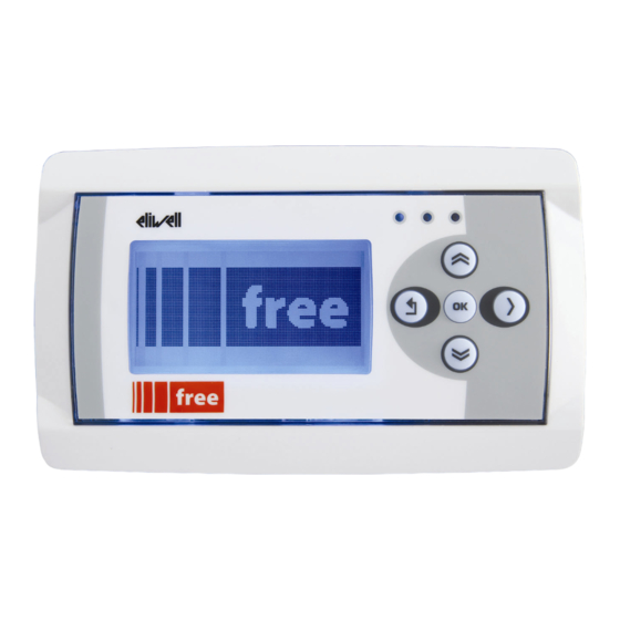
USER INTERFACE The interface, comprising the front cover of the controller, allows you to perform all operations needed to use the device. <IMG INFO> Keys and LEDs The LEDs be programmed from the IEC application. The keys be programmed from the IEC application. By default, the device displays a short menu containing the following default settings. -
Page 17: First Power On
First power on When the instrument is powered up for the first time, a few summary pages are displayed showing system status (SYSTEM INFO) SYSTEM INFO BIOS DATE BOOT EEPROM NOR FLASH NAND FLASH SDRAM BATRAM The system will also search for the PLC application and the local menu… If present, the menu will appear on the display PLC searching... -
Page 18: Hmi Management
5.3.2 HMI Management Remote Interface paragraph 5.3.3 Probe values Shows input values (read only) EVP has 3 inputs. Example EVP3500/C/RH Probes values Probes values Probes values Internal NTC External NTC Humidity sensor 27.3 - - - - - - - - - - - - - - 43.38 °C, °F °C, °F... -
Page 19: Com Setting
To move from one page to the next press the UP and DOWN keys After selecting the desired menu move the cursor onto to view the menu Launch remote page Please Wait If OK the display will show the selected menu (IEC application) If the menu is not present, the following screen appears Warning Upload failed... -
Page 20: Parameters
PARAMETERS User-parameterization renders the FREE Panel EVP fully configurable. Parameters can be changed using: Keys on the EVP front panel PC and FREE Studio software The following sections provide a detailed analysis of each parameter, divided into categories (folders). Table of parameters The following table contains all the device configuration parameters... - Page 21 parameters Map code ACKNOWLEDGEMENT Par_TAB 15716 WORD 0 … 65535 num. Note: read/write parameter Model Code ACKNOWLEDGEMENT Par_POLI 15717 WORD 0 … 65535 1025 num. Note: read/write parameter Parameter changed Flag indicating change to default settings. ACKNOWLEDGEMENT Par_PARMOD 15719 BOOL ...
- Page 22 Temperature unit of measure ANALOGUE Temp_UM 15725 WORD 0 = °C; 0 ... 1 num. INPUTS 1 = °F Type of analogue input Ai1 ANALOGUE 0= NTC (NK103) Cfg_AI1 15726 WORD 0 ... 2 num. INPUTS 1= DI ...
- Page 23 On-board RS485 serial address RS485 Addr_RS485_OB 15774 WORD The actual address is determined by the sum of this value + 0 ... 255 num. ON BOARD the value of the dip switch. On-board RS485 protocol selection RS485 Proto_RS485_OB 15775 WORD 2 = uNET 2 ...
- Page 24 ON BOARD ETHERNET WEB SERVER FUNCTIONALITY: For more details refer to document 9IS24252_Web_ApplicationNotes parameters necessary for the configuration of ports and protocols are these: HTTP and TFTP ports FREE WEB allows the use of HTTP and TFTP servers HTTP HyperText Transfer Protocol. An HTTP server generally listens on port 80 using TCP protocol.
- Page 25 DNS system System for the conversion of host names, or network nodes, to IP addresses Used by FREE Studio to send text e-mails (strings) value value Primary DNS server PriDNS_1_ETH SecDNS_1_ETH Secondary DNS server (part 1) (part 1) Primary DNS server PriDNS_2_ETH SecDNS_2_ETH Secondary DNS server (part 2)
- Page 26 ETHERNET DefGtwy_1_ETH 15802 WORD Default Gateway (part 1) 0 … 255 num. ON BOARD ETHERNET DefGtwy_2_ETH 15803 WORD Default Gateway (part 2) 0 … 255 num. ON BOARD ETHERNET DefGtwy_3_ETH 15804 WORD Default Gateway (part 3) 0 … 255 num. ON BOARD ETHERNET DefGtwy_4_ETH...
- Page 27 ETHERNET PriDNS_1_ETH 15810 WORD RW Primary DNS server (part 1) 0 … 255 num. ON BOARD ETHERNET PriDNS_2_ETH 15811 WORD RW Primary DNS server (part 2) 0 … 255 num. ON BOARD ETHERNET PriDNS_3_ETH 15812 WORD RW Primary DNS server (part 3) 0 …...
- Page 28 Display language 0 = Italian 1 = English Display Hmi_Language 15819 WORD 0 … 65535 num. 2 = French 3 = German 4 = Spanish LCD Contrast Display Par_ContrLCD 15723 WORD 0 … 64 Num. Allows adjustment of the LCD display contrast.
- Page 29 HMI Management Hmi_Language 15989 WORD 0 … 65535 num. Current HMI 0= HMI remote 1 1= HMI remote 2 2= HMI remote 3 3= HMI remote 4 4= HMI remote 5 HMI Management HmiList_Current 15820 WORD 5= HMI remote 6 0 …...
- Page 30 HMI remote 3 HmiList_ID_3 15823 WORD RW HMI remote 3 navigation ID list 0 ... 254 num. HMI remote 3 navigation resource type 1=RTU (RS485 Modbus RTU) HMI remote 3 HmiList_Res_3 15835 WORD 1 … 3 num. 2=TCP (Modbus TCP) 3=CAN (CANopen) HMI remote 3 navigation resource address for CAN, RTU and TCP...
- Page 31 HMI remote 6 HmiList_ID_6 15826 WORD RW HMI remote 6 navigation ID list 0 ... 254 num. HMI remote 6 navigation resource type 1=RTU (RS485 Modbus RTU) HMI remote 6 HmiList_Res_6 15838 WORD 1 … 3 num. 2=TCP (Modbus TCP) 3=CAN (CANopen) HMI remote 6 navigation resource address for CAN, RTH and TCP...
- Page 32 HMI remote 9 HmiList_ID_9 15829 WORD RW HMI remote 9 navigation ID list 0 ... 254 num. HMI remote 9 navigation resource type 1=RTU (RS485 Modbus RTU) HMI remote 9 HmiList_Res_9 15841 WORD 1 … 3 num. 2=TCP (Modbus TCP) 3=CAN (CANopen) HMI remote 9 navigation resource address for CAN, RTU and TCP...
-
Page 34: Models And Accessories
Accessories for Wall Mounting Contact the Eliwell Sales Department for wall-mounting accessories. Make 4 holes of diameter 4.2mm in the wall at the specified spacing, to fix the backplate. Alternatively use the two side slots, one at the bottom and one at the top, under the corresponding break-open removable doors, preventing the opening of holes in walls with recessed-wall wiring. -
Page 35: Accessories
Name Code Description Notes USB/485 MINI KIT converter SAR0RA00X701 + USB cable Converters and cables EVA00USCA0000 USB/CAN converter Contact Eliwell Cable Ethernet cable Sales Department 230V~/24V 25VA transformer Note: cable must be no longer TF111202 than 10m Transformer 230V~/24V 35VA... - Page 36 Range from -0.5/7bar to 0/50 bar EN-IT-ES-DE-FR-RU Depending on model IMG INFO Documentation / Code Description Notes Contact Eliwell Contact Eliwell Sales Software Tools Sales Department FREE Studio Department IMG INFO VAL00033K Demo case Demo Case FREE Evolution IMG INFO...
- Page 38 ANALITIC INDEX I/O features ..............14 Improper Use..............15 Accessories............... 35 INTRODUCTION..............3 Analogue inputs ..............9 Analogue Inputs-Probes ..........6 Keys and LEDs..............16 BIOS parameters ............17 Language................18 BRIDGE ................13 Mechanical dimensions ..........15 CAN..................6 MECHANICAL INSTALLATION ........5 CAN connection example (Field)........ 10 Models................34 CANopen network connection example....
- Page 39 Facsimile +39 0437 989 066 Sales: +39 0437 986 100 (Italy) +39 0437 986 200 (other countries) saleseliwell@invensys.com Technical helpline: +39 0437 986 250 E-mail eliwell.freeway@invensys.com www.eliwell.com FREE Panel 2012/05/ Cod: 9MA10046 © Eliwell Controls s.r.l. 2011-12 All rights reserved.
Need help?
Do you have a question about the FREE Panel EVP 3300/C and is the answer not in the manual?
Questions and answers