
Related Manuals for Panasonic AW-360B10


Summary of Contents for Panasonic AW-360B10
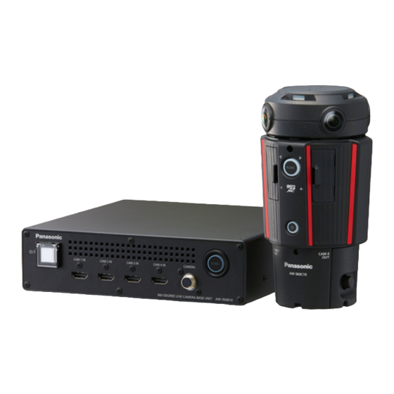
- Page 1 Operating Instructions 360-degree Live Camera Base Unit AW-360B10 Model No. Before operating this product, please read the instructions carefully and save this manual for future use. ENGLISH W0917HK1018 -FJ DVQP1395YA...
- Page 2 Svenska Besök följande webbplats för senaste säkerhetsinformation och viktiga meddelanden om produkten. http://pro-av.panasonic.net/en/manual/index.html Manufactured by: Panasonic Corporation, Osaka, Japan Importer’s name and address of pursuant to EU rules: Panasonic Marketing Europe GmbH Panasonic Testing Centre Winsbergring 15, 22525 Hamburg, Germany...
- Page 3 ≥ microSD Memory Card, microSDHC Memory Card and microSDXC Memory Card are referred to as the “microSD card”. ≥ The unit “360-degree Live Camera Base Unit (AW-360B10)” is referred to as the “Base Unit”. ≥ The optional “360-degree Live Camera Head (AW-360C10)” is referred to as the “Camera Head”.
-
Page 4: Read This First
Read this first! Information for Your Safety WARNING: AVERTISSEMENT: To reduce the risk of fire, electric shock or product Afin de réduire les risques d’incendie, de chocs damage, électriques ou d’endommagement du produit, ≥ Do not expose this unit to rain, moisture, dripping ≥... -
Page 5: Important Safety Instructions
∫ IMPORTANT SAFETY INSTRUCTIONS ∫ Directives importantes Read these operating instructions carefully before using Avant d’utiliser l’appareil, lire attentivement les instructions the unit. Follow the safety instructions on the unit and the qui suivent. Se conformer tout particulièrement aux applicable safety instructions listed below. Keep these avertissements inscrits sur l’appareil et aux consignes de operating instructions handy for future reference. - Page 6 Declaration of Conformity Model Number: AW-360B10 Trade Name: Panasonic Responsible Party: Panasonic Corporation of North America Two Riverfront Plaza Newark NJ07102 Support contact: 1-800-524-1448 This device complies with Part 15 of the FCC Rules. Operation is subject to the following two conditions: (1) This device may not cause harmful interference, and (2) this device must accept any interference received, including interference that may cause undesired operation.
- Page 7 For more information about collection and recycling, please contact your local municipality, dealer or supplier. Penalties may be applicable for incorrect disposal of this waste, in accordance with national legislation. Інформація для покупця Виробник: Panasonic Corporation Панасонік Корпорейшн Адреса виробника: Kadoma, Osaka, Japan Кадома, Осака, Японія Країна походження: Japan Японія...
-
Page 8: Table Of Contents
Contents Read this first! ............4 Maintenance Information for Your Safety........4 Preparation Warning Indications ..........54 Messages ..............55 Troubleshooting ............56 Operating precautions ..........9 Repairing microSD cards Accessories .............. 14 in the Camera Head ..........60 Optional accessories ..........14 What you can do with this system ...... -
Page 9: Preparation
When connecting to the dedicated Camera Head (AW-360C10) ≥ Always use a genuine Panasonic Camera head option cable (AG-C20003G (3 m (9.8 feet)): optional). ≥ Always use a genuine Panasonic HDMI Cable (AW-CAH103G: optional). When connecting to a network ≥... - Page 10 Do not extend the optional cables to be used. Do not spray insecticides or volatile chemicals onto the unit. ≥ If the unit is sprayed with such chemicals, its body may be marred and the surface finish may peel off. ≥...
-
Page 11: Disclaimer Of Warranty
This unit (AW-360B10) is compatible only to the dedicated camera head AW-360C10. It will not operate if any other model is connected. The camera head AW-360C10 will not operate when connected to any base unit other than this unit (AW-360B10). ∫ Regarding system frequencies It is possible to switch the system frequency (59.94 Hz/50.00 Hz) with this unit by changing the setup for outputting... - Page 12 ∫ Network security As you will use the unit connected to a network, your attention is called to the following security risks. Leakage or theft of information through the unit Use of the unit for illegal operations by persons with malicious intent Interference with or stoppage of the unit by persons with malicious intent It is your responsibility to take precautions such as those described below to protect yourself against the above network security risks.
- Page 13 Be careful about the possibility of theft or loss of the unit, and be careful not to leave the unit unattended. Please note that Panasonic does not accept any responsibility for the compromise, manipulation, and loss of information caused by these events.
-
Page 14: Accessories
Preparation Accessories Check the accessories before using this unit. Cable strap (k2) ≥ To purchase extra accessories, contact your dealer. ≥ After removing the product from its container, dispose of the packing materials in an appropriate manner. Preparation Optional accessories Some optional accessories may not be available in some countries. -
Page 15: What You Can Do With This System
Preparation What you can do with this system This unit is the Base Unit of the 360-degree Live Camera. The 360-degree Live Camera comes with the following features. ≥ It is possible to combine images recorded with four camera units together by using real-time stitching technology capable of CAM4 minimizing time lag. - Page 16 Cross-platform operation using a web browser Operate the web browser of the PC connected via wired LAN or the iPad connected via a wireless access point to configure various settings of the unit. Cross-platform operation is made possible by the use of a web browser. ...
-
Page 17: Names And Functions Of Main Parts
Preparation Names and Functions of Main Parts Power button [ 21)/ ≥ The function lamp lights while a card is being Status indicator accessed. For example, it will light when you format a ≥ The status indicator normally lights or flashes in green. card on the Camera Head. - Page 18 Air Inlet (cooling fan) Verify the pin positions of the output Maintenance port [MAINTENANCE] connector of the DC power supply and the ≥ This port is used for maintenance of the unit. (Not unit’s DC IN terminal, and be sure to normally used) connect with the correct polarities.
-
Page 19: Connecting This Unit To The Camera Head
Preparation Connecting this unit to the Camera Head ≥ Be sure to turn off this unit before attaching or removing the camera head option cable and HDMI Cables. A Type D terminal C Camera head option cable B Type A terminal D HDMI Cable (k4) Attaching the Camera head option cable (optional) - Page 20 Insert the Type D connector 2 of each of the HDMI Cables into one of the video output terminals 3 (illustrated example: CAM1 OUT terminal) of the Camera Head. ≥ Insert the HDMI Cables to all of the CAM1 OUT-CAM4 OUT terminals. ...
-
Page 21: Turning The Unit On/Off
Preparation Turning the unit on/off Connect a DC power source to the DC input terminal 18) of the unit. ≥ The unit will turn on and the status indicators of the unit and the Camera Head will light in green. ≥... -
Page 22: Shooting
Shooting Before Shooting ≥ When shooting, make sure your footing is stable and there is no danger of colliding with another person or object. ≥ Do not block the air inlet or air outlet of the cooling fan with your hands, etc. 17, 18) ≥... -
Page 23: Web Screen Operations
≥ For the most recent information on compatible operating systems and web browsers, visit the support desk at the following web site. http://pro-av.panasonic.net/ ≥ The operation procedures and screen shots in this document is explained with Windows 10 and Google Chrome. -
Page 24: Displaying The Web Screen
Web screen operations Displaying the web screen Operate the web browser of the PC connected via wired LAN or the iPad connected via a wireless access point to configure various settings of the unit. ... - Page 25 Displaying the web screen The instructions provided in this document are based on the screen for Windows (Google Chrome), but the same procedures apply to Mac (Safari) and iPad * There may be differences in some parts of the screen displays. Open the web browser.
-
Page 26: User Authentication
User authentication To prevent infringement of privacy and personality rights, information leaks, and other issues concerning unauthorized access by third parties, change the settings of the user authentication function from their factory defaults upon installation. Getting started: ≥ Operate the PC connected to the unit to display the web screen of the unit 24). -
Page 27: About The Main Screen
Web screen operations About the main screen The instructions provided in this document are based on the screen for Windows (Google Chrome). ≥ The displayed items may differ depending on various factors such as the operating system of the PC and the usage environment. -
Page 28: Stitching Adjustment
Web screen operations Stitching adjustment Specify the automatic parallax correction setting (the setting for automatically adjusting image stitching seams) and if necessary, adjust the area displayed by each camera unit. The area displayed by each camera unit can be adjusted only when the Automatic Parallax Correction Mode is set to [Off]. - Page 29 Adjust the image stitching seams of each camera unit Click the stitching adjustment button 1. Select [Off] from the pull-down menu 2. Click the main area 3 to select the camera unit to be adjusted.
-
Page 30: Making Adjustments On The Advanced Adjustment Screen
Making adjustments on the advanced adjustment screen Use the pull-down menu 1 to change the mode to [Off]. Click the advanced adjustment tab 2. Click the item to be set, and enter values. [PAN] Moves the image horizontally. -
Page 31: Exposure (Gain/Shutter Speed) Adjustment
Web screen operations Exposure (gain/shutter speed) adjustment Adjust the exposure (gain and shutter speed). In Master Camera Mode, it is possible to apply the setup of the master camera to all areas of the 360-degree video through coordinated exposure control. This mode can only be set on the advanced adjustment screen. ≥... -
Page 32: Making Adjustments On The Advanced Adjustment Screen (Master Camera Mode)
Making adjustments on the advanced adjustment screen (Master Camera Mode) Click the advanced adjustment tab 1. (When [Master] is displayed) Click [Master] 2 to switch to the Master Camera Mode. Click the item to be set. [CAM1] Use the pull-down menu to change the master camera. -
Page 33: Making Adjustments On The Advanced Adjustment Screen (Detail Mode)
Making adjustments on the advanced adjustment screen (Detail Mode) Click the advanced adjustment tab 1. (When [Detail] is displayed) Click [Detail] 2 to switch to Detail Mode. Click the item to be set. [Auto] Use the pull-down menu to change the mode. -
Page 34: White Balance
Web screen operations White Balance Adjust the White Balance. In Master Camera Mode, it is possible to apply the setup of the master camera to all areas of the 360-degree video through coordinated White Balance control. The setup can only be configured on the advanced adjustment screen. It is possible to fine-adjust the White Balance on the advanced adjustment screen. -
Page 35: Making Adjustments On The Advanced Adjustment Screen (Master Camera Mode)
Making adjustments on the advanced adjustment screen (Master Camera Mode) Click the advanced adjustment tab 1. (When [Master] is displayed) Click [Master] 2 to switch to the Master Camera Mode. Click the item to be set. [CAM1] Use the pull-down menu to change the master camera. -
Page 36: Making Adjustments On The Advanced Adjustment Screen (Detail Mode)
Making adjustments on the advanced adjustment screen (Detail Mode) Click the advanced adjustment tab 1. (When [Detail] is displayed) Click [Detail] 2 to switch to Detail Mode. Click the item to be set. [Auto] Use the pull-down menu to change the mode. -
Page 37: Saving/Loading The Image Quality Setup Information
Web screen operations Saving/loading the image quality setup information A maximum of 10 items of image quality setup information can be saved. It is also possible to load saved setup information. ≥ The following types of setup information can be saved/loaded. j Exposure adjustment j White balance j The settings of [Upside-down] on the system setup screen ([System Mode]) -
Page 38: Loading Image Quality Setup Information
Loading image quality setup information Click the load image quality setup button 1. Click the setup information to be loaded 2. ≥ Select [Default] 3 to return the image quality settings to the factory defaults. Click the [Load] button 4 to load the setup information. -
Page 39: Settings Screen
Web screen operations Settings screen Configure the unit's settings other than those of picture quality. Click the settings button 1. Click the tab to be set in 2 to display the setup screen corresponding to the tab. [General] Displays the basic setup screen. -
Page 40: Basic Setup Screen [General]
Basic setup screen [General] Configure the unit's basic settings such as device name and user authentication. 1 Camera Name Input the name of the camera here. When the [OK] button is clicked, the input name appears in the camera title display area. Factory settings: Panasonic360 ≥... - Page 41 4 Protect Configure the user authorization settings for the personal computers and iPad that can access the unit. Click the [Setting] button to display the user authentication setup screen. ≥ Log in again after changing the settings. ∫ User authentication setup screen User ID The user name is input here.
-
Page 42: Image Output Setup Screen [Video Output]
Image output setup screen [Video Output] Configure the settings for outputting images to the external device through the HDMI Cables. VIDEO OUT 1 Output Mode Changes the output resolution of images that are output to the external device through the HDMI Cables. The available setting values vary depending on the [Capture Mode] setting. -
Page 43: System Setup Screen [System Mode]
Audio Out 3 L CH/R CH CAM4 CAM1 Sets the Camera Head's built-in microphones (MC1-MC4) to be used as L CH/R CH devices that output audio through the HDMI Cables. Setting value: L CH/R CH (OFF, MC1, MC2, MC3, MC4) Factory settings: L CH (MC2)/R CH (MC3) ≥... -
Page 44: Network Setup Screen [Networks]
The IP address that was automatically assigned with DHCP can be viewed using the “Easy IP Setup Software”. (Windows only) The software can be downloaded from the support website below. http://pro-av.panasonic.net/ ≥ The network settings of the unit cannot be configured with the “Easy IP Setup Software”. - Page 45 4 Default gateway Input the unit’s default gateway if the DHCP function is not going to be used. Factory settings: 192.168.0.1 ≥ Multiple IP addresses cannot be used for the default gateway even when the DHCP function is used. For details on the DHCP server settings, consult your network administrator.
- Page 46 : Protocol This sets the method to connect to the unit. Setting value: http Only HTTP connection is possible. Only HTTPS connection is possible. https ≥ If you select [https], the unit cannot be connected from an iPad. Factory settings: http ≥...
- Page 47 Accessing the unit from the PC by HTTPS Launch the web browser in your personal computer. Enter the IP address of the unit in the address bar of the web browser. ≥ Example of input: https://192.168.0.10/ If the port number is set to a value other than [443] ([Port]: ≥...
- Page 48 ∫ Mac Click [Show Certificate]. ≥ If you click [Continue], this message may not appear again and, as a result, you may not be able to access the unit. To display the message again, try the following operations and access the address again. j If the certificate of the unit is stored in [Keychain Access] in [Utilities], delete it.
-
Page 49: Camera Setup Screen [Camera]
Camera setup screen [Camera] Adjust the area displayed by each camera unit. ≥ Select the camera unit in 1 and set the items 2-4. ≥ If you change any setting of 2 [Offset], 3 [ZOOM] or 4 [Posture On The Camera] or if you click the [Default] button of 5 [Default Data Set], the automatic parallax correction setting ([Parallax Correction]: 50) will change to [Off]. -
Page 50: Stitching Setup Screen [Stitching]
Stitching setup screen [Stitching] Configure the stitching settings for combining images into 360-degree video. 1 Picture Shift Rearranges the camera unit images of the 360-degree video. Setting value: 0 to 3 Factory settings: 0 ≥ If you set [Upside-down] 43) to [ON], the camera unit positions will be rearranged in reversed left-right order. -
Page 51: Memory Card Format Screen [Sd Card Format]
Memory card format screen [SD Card Format] Format a microSD card in the Camera Head. To update the firmware of the Camera Head, format a microSD card on the unit. ≥ Please be aware that if a medium is formatted, then all the data recorded on the medium will be erased and cannot be restored. -
Page 52: Product Information Screen [Product Info.]
Product information screen [Product Info.] Product information, such as the firmware versions of this unit and the Camera Head, are displayed. Camera Head 1 Firmware Version (CAM1-CAM4) Displays the firmware version of the Camera Head. ∫ To update the firmware of the Camera Head Download the update file available from the support website, and save it on a microSD card. -
Page 53: Hour Meter Screen [Hour Meter]
Firmware update information For the most current information regarding the update, confirm at the following support site. http://pro-av.panasonic.net/ ≥ Updating is not possible with illegal firmware files. ≥ It takes about 40 minutes to update the firmware of the unit. Use a DC power source with enough charge. Do not operate the unit while a firmware update is in progress. -
Page 54: Warning Indications
Maintenance Warning Indications If a problem is detected immediately after the unit is turned on or while you are operating it, the status indicators of the unit and the Camera Head and a web screen indication report the problem. Status indicator The status indicator of the unit flashes in red. -
Page 55: Messages
The status indicators of the unit and the Camera Head light up in Status indicator red. The message [Fan Error in Camera Head. Turn Power Off.] is Web screen indication displayed. Camera Head The cooling The cooling fan of the Camera Head has stopped due to an error in fan has the fan. -
Page 56: Troubleshooting
Maintenance Troubleshooting ∫ It is not a malfunction in following cases ≥ Object seems to be warped slightly when the object moves across the image Object seems to be warped. very fast, but this is because the Camera Head is using MOS for the image sensor. - Page 57 Problem Check points The pictures are too light or ≥ Set the [Mode] for exposure adjustment to [Auto]. too dark When fine lines or cyclical ≥ This phenomenon occurs because the pixels are arranged systematically on patterns are shot, flickering each image sensor.
- Page 58 “Easy IP Setup Software”. The software can be downloaded from I don't know the IP address. the support website below. http://pro-av.panasonic.net/ j The network settings of the unit cannot be configured with the “Easy IP Setup Software”. ≥ Connect the LAN cable with Category 5 or above to the IP control LAN connector.
- Page 59 Problem Check points ≥ Images are not displayed on the web screen if the unit is not outputting them to the external device through the HDMI Cables. Verify that the unit and the external device are connected correctly with the HDMI Cables. ≥...
-
Page 60: Repairing Microsd Cards In The Camera Head
Problem Check points ≥ Convergence of transmission lines or some other factor may be making it The images break up impossible for the video information to be transmitted properly, causing the images to break up. Consult with the network administrator. The screen goes dark when the ≥... -
Page 61: Appearance
Specification Appearance Unit: mm [inch] 75 [2-15/16] 26.5 [1-1/32] Air inlet 10.4 [13/32] 6-M3 Depth 5 [3/16] 11 [7/16] 11 [7/16] 11 [7/16] 194 [7-5/8] 194 [7-5/8] 194 [7-5/8] 6.5 [1/4] 0.8 [1/32] 0.8 [1/32] 0.8 [1/32] 210 [8-9/32] 210 [8-9/32] 210 [8-9/32] 0.8 [1/32] 0.8 [1/32]... -
Page 62: Specification
Specification Specification 360-degree Live Camera Base Unit General Digital video System Frequency: Power: 59.94 Hz ([Capture Mode] = [NTSC])/ DC ( ) 12 V (11.5 V ˗ 17 V) 50.00 Hz ([Capture Mode] = [PAL]) Power consumption: The setting can be changed in [Capture Mode] When the special camera head (AW-360C10) is Video signal for external output: connected;... - Page 63 External terminal CAMERA terminal (These terminals connect to the dedicated Camera Head AW-360C10): 20-pin dedicated interface LAN: IP control LAN connector (RJ-45) With straight cable/crossover cable automatic recognition function DC IN 12 V: DC 12 V (11.4 V - 12.6 V) EIAJ Type4 Network section Video compression format: Motion JPEG...
- Page 64 Web Site: http://www.panasonic.com © Panasonic Corporation 2017...
Need help?
Do you have a question about the AW-360B10 and is the answer not in the manual?
Questions and answers