Table of Contents
Advertisement
Quick Links
Advertisement
Table of Contents

Related Manuals for CYP OR-IR88


Summary of Contents for CYP OR-IR88
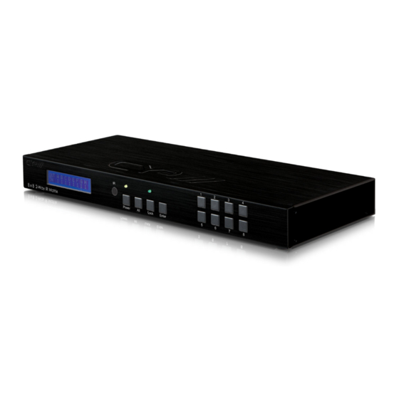
- Page 1 OR-IR88 8 x 8 Bi-Directional Infra Red Matrix Switcher OPERATION MANUAL...
-
Page 2: Safety Precautions
Safety Precautions Please read all instructions before attempting to unpack or install or operate this equipment, and before connecting the power supply. Please keep the following in mind as you unpack and install this equipment: Always follow basic safety precautions to reduce the risk of fire, electrical shock and injury to persons. -
Page 3: Table Of Contents
Table of Contents Introduction…………………………………………………..………. Applications……………………..…………………………....…. Package Contents…………………………..…………….....… System Requirements……...…………………..….…………..……. Features……………………………………………..……..……… Specifications..………………………………………...………...…. Hardware Description………………...……..….....…… Front Panel ................Rear Panel …………………………………………..…….… IR Cable Pin Definitions………………...……..….....…… Remote Control …….………....…………..…..…..…... 9.1 IR Custom Code................9.2 Discrete IR codes for 8x8 HDMI matrix (IR3)......10. RS-232 Protocols.................. 10.1 Pin Assignment................ -
Page 4: Introduction
1. Introduction The Bidirectional Infrared 8 by 8 IR Matrix is designed to work with HDMI matrix together and allow the IR function to control your source devices from beside your display/source. Using the original remote, you can control DVD/Blu-ray players, satellite and set-top-boxes and with a cross matrix design this device gives anyone the ability to send infrared signals from place to place. -
Page 5: Specifications
6. Specifications IR Frequency 30KHz to 50KHz Source Ports 8 x independent IR Blasters; 8 x independent IR Receivers; 1 x All IR blaster control; 1 x All IR receiver control; TV ports 8 x independent IR Receiver; 8 x independent IR Blaster; 1 x All IR blaster control;... -
Page 6: Hardware Description
7. Hardware Description The following sections describe the hardware components of the unit. 7.1 Front Panel 8x8 IR Matrix Power Lock Enter SOURCE RS232 LCM monitor: This screen will display the IR's source and TV selection DC 5V RS232 MAIN setting. -
Page 7: Rear Panel
8x8 IR Matrix Power Lock Enter 7.2 Rear panel SOURCE RS232 DC 5V RS232 MAIN RS-232 AUX: This slot is where you connect the D-Sub 9pin with the desire device for sending the RS-232 control signal. RS-232 MAIN: This slot is where you connect the D-Sub 9pin from the PC/NB ②... -
Page 8: Ir Cable Pin Definitions
8. IR Cable Pin Definitions IR Receiver IR Blaster ① Power 5V ① IR signal ② IR blaster signal ② Power 5V ③ NC ③ Grounding ① ② ③ ① ② ③ Note: Both the IR Receiver & Blaster can support a frequency of 30~50KHz. -
Page 9: Remote Control
9. Remote Control This remote control can be set with multipal format according to the dipswitch setting. There are total of four dipswitches with mainly two kinds of settings. When dipswitches are all set to ON/ ↑ the remote control is able to control all outputs and all inputs. For example, when output A wish to select input 5. -
Page 10: Rs-232 Protocols
10. RS-232 Protocols 10.1 Pin Assignment IR88 Remote Control Console Assignment Assignment Baud Rate: 9600bps Data bit: 8 bits Parity: None Stop bit: 1 Flow Control: None... -
Page 11: Commands
10.2 Commands COMMAND ACTION POWER 00 Power Off (standby) POWER 01 Power On PORT 11 Output A select Input1 PORT 12 Output A select Input2 PORT 13 Output A select Input3 PORT 14 Output A select Input4 PORT 15 Output A select Input5 PORT 16 Output A select Input6 PORT 17... - Page 12 PORT 47 Output D select Input7 PORT 48 Output D select Input8 PORT 51 Output E select Input1 PORT 52 Output E select Input2 PORT 53 Output E select Input3 PORT 54 Output E select Input4 PORT 55 Output E select Input5 PORT 56 Output E select Input6 PORT 57...
-
Page 13: Connection And Installation
11. Connection and Installation PU-1109RX CAT-6 100m PU-1109TX PU-1109RX PU-1109RX PU-1109RX... - Page 14 OR-IR88 ° ° A B C D E F G H 1 2 3 4 5 6 7 8 IR Cable HDMI Cable HDMI Cable OR-HD88S IR Cable...
-
Page 15: Acronyms
Acronyms Acronym Complete Term Infrared 20110704 MPM-CMIR-882... - Page 16 www.cypeurope.com...
Need help?
Do you have a question about the OR-IR88 and is the answer not in the manual?
Questions and answers