Table of Contents
Advertisement
Quick Links
Advertisement
Table of Contents

Related Manuals for CYP OR-44-4K22


Summary of Contents for CYP OR-44-4K22
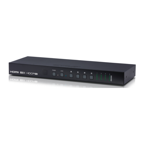
- Page 1 OR-44-4K22 4 x 4 HDMI Matrix Switcher (4K, HDCP2.2, HDMI2.0) OPERATION MANUAL...
- Page 3 DISCLAIMERS The information in this manual has been carefully checked and is believed to be accurate. CYP (UK) Ltd assumes no responsibility for any infringements of patents or other rights of third parties which may result from its use. CYP (UK) Ltd assumes no responsibility for any inaccuracies that may be contained in this document.
-
Page 4: Safety Precautions
SAFETY PRECAUTIONS Please read all instructions before attempting to unpack, install or operate this equipment and before connecting the power supply. Please keep the following in mind as you unpack and install this equipment: • Always follow basic safety precautions to reduce the risk of fire, electrical shock and injury to persons. -
Page 5: Table Of Contents
CONTENTS 1. Introduction ...........6 2. Applications ...........6 3. Package Contents ........6 4. System Requirements ......7 5. Features ..........7 6. Operation Controls and Functions ..8 6.1 Front Panel ........... 8 6.2 Rear Panel ............. 9 6.3 Remote Control ........10 6.4 IR Pin Definitions ........11 6.5 RS-232 Protocols ........11 6.6 Telnet and RS-232 Commands ....12 6.7 Telnet Control ..........15... -
Page 6: Introduction
1. INTRODUCTION This 4x4 4K UHD Matrix provides a high level of audio and video performance with support for resolutions up to 4K@60Hz (YUV 4:4:4, 8-bit) and pass-through support of digital audio formats including LPCM 7.1 (with sampling rates up to 192kHz), bitstream, and HD bitstream. The 4 HDMI inputs and 4 HDMI outputs support fully matrixed switching. -
Page 7: System Requirements
4. SYSTEM REQUIREMENTS HDMI source equipment such as media players, video game consoles or set-top boxes. HDMI receiving equipment such as HDTVs, monitors or audio amplifiers. The use of “Premium High Speed HDMI” cables is highly recommended. 5. FEATURES HDMI inputs and outputs with 18Gbps (600MHz) 4K UHD support DVI 1.0 compliant with the use of an HDMI-DVI adaptor HDCP 1.4 and 2.2 compliant Supports HD resolutions up to 3840x2160@60 Hz (YUV 4:4:4, 8-bit) &... -
Page 8: Operation Controls And Functions
6. OPERATION CONTROLS AND FUNCTIONS 6.1 Front Panel POWER LOCK IR Window: Accepts IR signals from the included IR remote for control of this unit only. Power Button & LED: Press this button to power the unit on (green LED) or place it into stand-by mode (red LED). LOCK&... -
Page 9: Rear Panel
6.2 Rear Panel OUTPUT INPUT POWER IR IN RS232 CONTROL DC 24V SERVICE INPUT 1~4: Connect to HDMI source equipment such as media players, game consoles or set-top boxes. DVI sources are supported with the use of an HDMI to DVI adapter. OUTPUT A~D: Connect to HDMI TVs, monitors or amplifiers for digital video and audio output. -
Page 10: Remote Control
6.3 Remote Control POWER: Press this button to POWER power the unit on or place it into stand-by mode. OUTPUT OUTPUT A: Press the number of the input (1~4) to display OUTPUT on Output A. OUTPUT B: Press the number OUTPUT of the input (1~4) to display on Output B. -
Page 11: Ir Pin Definitions
6.4 IR Pin Definitions IR Extender IR Signal Power Grounding 6.5 RS-232 Protocols MATRIX REMOTE CONTROLLER Definition Definition ► ◄ Baud Rate: 115200bps Data bit: 8 bits Parity: None Flow Control: None Stop Bit: 1... -
Page 12: Telnet And Rs-232 Commands
6.6 Telnet and RS-232 Commands COMMAND DESCRIPTION DESCRIPTION OF PARAMETER Switch Output A N=1~4 to Input N Switch Output B N=1~4 to Input N Switch Output C N=1~4 to Input N Switch Output D N=1~4 to Input N Switch All Output N=1~4 to Input N AB….. - Page 13 COMMAND DESCRIPTION DESCRIPTION OF PARAMETER PRESET N Preset the store I/ N=1~4 O Position N Name N N1 Name port N as N=1~4 N1=ABCDEFGH(Max Length=8) Show Unit NONE Firmware Version EM N N1 Setting port N N=1~4 EDID Mode to N1 N1= 1-FHD2CH, 2-FHDMCH, 3-4KUHD2CH,...
- Page 14 COMMAND DESCRIPTION DESCRIPTION OF PARAMETER USBISP Update FW by USB NONE HELP Display all NONE available commands and its description Display all NONE available commands QUIT Quit Telnet NONE Note: Commands will not be executed unless followed by a carriage return. Commands are not case-sensitive.
-
Page 15: Telnet Control
6.7 Telnet Control the PC/Laptop are connected to the same active networks. To access Telnet in Windows 7, click on the “Start” menu and type “cmd” in the search field, then press “Enter”. Under Windows XP go to the “Start” menu, click on “Run”, type “cmd” then press “Enter”. -
Page 16: Webgui Control
This will connect us to the unit we wish to control. Type “help” to list the available commands. 6.8 WebGUI Control All primary functions of this unit are controllable via the built in WebGUI. This control is presented across 3 separate tabs, including Switch, EDID Settings, and System Settings. - Page 17 Connect the unit and your PC/Laptop to the same active network and execute the Device Discovery software. Click on “Find Devices on Network” and a list of devices connected to the local network will show up indicating their current IP address. By clicking on one of the listed devices you will be presented with the network details of that particular device.
- Page 18 • Log in to the WebGUI To access the WebGUI, open a web browser on a PC/Laptop that is connected to an active network and type the unit’s IP address into the web address entry bar. Log into the unit by entering the appropriate user name and password. Note: The default user name and password are “admin”.
- Page 19 change their colour to orange. The new route will become active immediately and the routing information displayed on the buttons will change accordingly. If you need to route an input to multiple outputs, please select all of the appropri- ate output buttons before selecting the input port. Renaming I/O: All inputs and outputs can be renamed as required.
- Page 20 Presets: This matrix can store up to 4 routing presets. Presets can be utilized to store mul- tiple different routing states in advance for rapid, hassle-free, recall. Preset Set: Once you have the matrix set the way you like, you can click the “store”...
- Page 21 4 presets. The preset will load immediately upon pressing the preset’s button. • EDID Settings Tab This matrix provides the option of six built in EDIDs, four sink sourced EDIDs and four user uploaded EDIDs that can be assigned to each input port individually. The names of the four user uploaded EDIDs can changed if desired.
- Page 22 EDID Selection: The EDID Settings section allows for the assignment of an EDID to each individual input port. Select the preferred EDID from each dropdown menu. The EDID will be changed immediately. Note: In some rare cases it is possible for custom or external EDIDs to cause compat- ibility issues with certain sources.
- Page 23 EDID Upload: To upload a custom EDID, please click the “Choose File” button below the User EDID that you would like to change. A file selection window will appear, allowing you to locate and upload your preferred EDID file from your local PC. The EDID should be in the *.bin file format.
-
Page 24: System Settings
System Settings • This page provides system configuration options including turning the power on/ off, changing the login password, changing the network settings, resetting the system to factory defaults, and updating the firmware. Web User Settings: To change the login password for the unit, enter the username as “admin”, type the current password in the “Old Password”... - Page 25 Network: The unit’s IP mode (DHCP or Static IP), IP address, netmask, and gateway can be set here. When the unit is set to “DHCP” mode, it will automatically attempt to obtain proper configuration information from the local DHCP server. If no DHCP server is available, or the user wishes to configure the network settings manually, please set the unit to “Static IP”...
-
Page 26: Connection Diagram
7. CONNECTION DIAGRAM Blu-ray/PS4 Player Blu-ray/PS4 Player Blu-ray/PS4 Player Blu-ray/PS4 Player OUTPUT INPUT POWER IR IN RS232 CONTROL DC 24V SERVICE Projector 6GHDMI TV/Display... -
Page 27: Specifications
8. SPECIFICATIONS 8.1 Technical Specifications Video Bandwidth 600MHz/18Gbps Input Ports 4× HDMI 1× IR 1× RS-232 1× Mini USB(Service) 1× RJ45(Control) Output Ports 4× HDMI Supported Resolutions 480i~1080p@24/50/60Hz 4K up to 4096×2160@60Hz (YUV 4:4:4, 8-bit) VGA~WUXGA IR Frequency 30~50 kHz Baud Rate 115200 bps Power Supply... -
Page 28: Timing
8.2 Timing DVI and HDMI Supported Resolutions (Hz) Input Output 640x480@60/72/75/85 720x400@85 800x600@56/60/72/75/85 1024x768@60/70/75/85 1152x864@75 1280x720@60 1280x768@60/75/85 1280x800@60 1280x960@60 1280x1024@60 1360x768@60 ... - Page 29 DVI and HDMI Supported Resolutions (Hz) Input Output 1920x1080i@50/59.94/60 1920x1080p@23.97/24/25/29.97/30/50/ 59.94/60 3840x2160@24/25/30/50/60 4096x2160@24/25/30/50/60 ...
- Page 32 CYP (UK) Ltd., Unit 7, Shepperton Business Park, Govett Avenue, Shepperton, Middlesex, TW17 8BA Tel: +44 (0) 20 3137 9180 | Fax: +44 (0) 20 3137 6279 Email: sales@cypeurope.com www.cypeurope.com v1.00...
Need help?
Do you have a question about the OR-44-4K22 and is the answer not in the manual?
Questions and answers