Table of Contents
Advertisement
Advertisement
Table of Contents

Related Manuals for RadioLink RC4GS


Summary of Contents for RadioLink RC4GS
- Page 1 RC4GS Digital 4 Channels Proportional RC System Instruction Manual CE FCC ROHS...
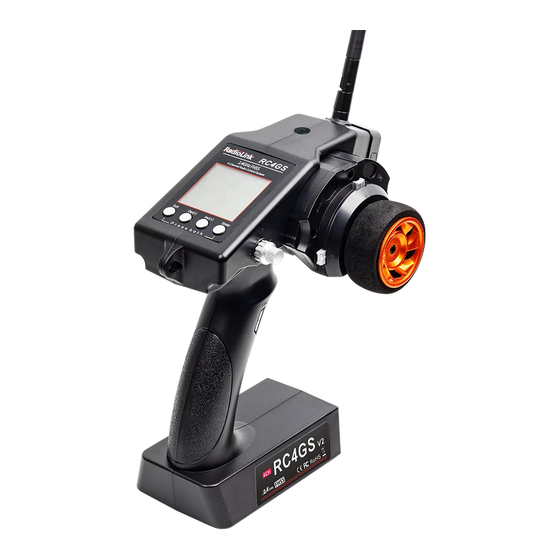
- Page 2 INTRODUCTION Thank you for choosing Radiolink 2.4 GHz 4CH pistol grip radio -- RC4GS. RC4GS is default 4 channels transmitter and comes with receiver R6FG with gyro integrated and HV supported servo. RC4GS, working with FHSS spread spectrum and 67 channels pseudo frequency sequence hopping, both transmitter and receiver use industrial chips to ensure superior anti-interference ability using the same frequency band, different frequency band and anti-sparks interference ability.
- Page 3 Important Safety Notice: The following two symbols will appear in this manual(please pay attention to the paragraph with this two symbols labeled): Prohibition Testing and confirmation Do not use in bad weather such as rainy or thundering to ensure the safety of you and others. Forbid to use this product in the crowd and the place against national law! You need to turn the throttle channel (CH3) and inch switch to the lowest before you use.
-
Page 4: Table Of Contents
3.2.1 Receiver Installation and Binding ....................6 3.2.2 Working Mode ..........................3.2.3 How to Turn On Gyro Function ..................... 7 4. RC4GS Functions ............................... 8 4.1 Display When Power Switch Turned On ..................... 8 4.2 Language Select "LANGUAGE" ....................... 9 4.3 Model Select "MODEL"... -
Page 5: Pistol Grip Control System
3. Pistol Grip Control System RC4GS, transmitter with chip STM32F103RB, receiver R6FG/R6F with 32 bits industrial chip, 12ms only from transmitter to the receiver, thus provide control synchronous and performance perfect. The same FHSS spread spectrum and 67 channels pseudo random frequency sequence hopping of AT9S makes RC4GS have superior anti-interference ability both at the same frequency band and different frequency bands. -
Page 6: Receiver
RF power: <20dbm Low Voltage alert: Yes (lower than 4.6V) , can be set when using 2-4S LiPo battery Receiver: R6FG, R6F, R8EF, R8FM 3.2 Receiver RC4GS comes with R6FG, 2.4GHz 6 channels receiver, gyro integrated and HV servo supported. -
Page 7: Receiver Installation And Binding
Specification (1) Frequency: 2.4GHz ISM band (2400MHz~2483.5MHz) (2) Size: 35*20*13mm (3) Channel: 6 (4) Model: cars/boats (5) Modulation mode: GFSK (6) Spread spectrum: FHSS (7) 10 modes memory storage (8) Antenna length: 200mm (9) Control distance: more than 400 meters (10) LCD screen: 128*64 resolution, LCD back light (11) -
Page 8: Working Mode
R6FG with two indicate LEDs, while green LED is on, it indicates normal working mode. While both green and red LEDs are on, it indicates gyro function working mode. 3.2.2 Working Mode R6FG has two working modes: normal working mode and gyro function working mode. Normal Working Mode Green LED, gyro will not working. - Page 9 When the gyro is enabled, pull the throttle trigger and then release (make sure the car stops running), turn the car right or left without changing steering wheel, if the servo will not follow with, it shows gyro is set backward. Press the binding switch one time for less than 1 second, the LED flashes red once;...
-
Page 10: Rc4Gs Functions
4. RC4GS Functions 4.1 Display When Power Switch Turned On LCD Screen When you power on the transmitter, LCD screen shows Model Name, Transmitter Name, Battery Voltage, Steering Trim, Throttle Trim. Model Name The system can store the data for 10 models, model name will show on the LCD when you power on the transmitter. -
Page 11: Model Select "Model
(4) (4) Press “Enter” button, the desired language is selected and return to the initial screen automatically. 4.3 Model Select "MODEL" RC4GS can store model memories for ten models. Use this function to call a new model. (1) Access the function menu (By pressing “Exit” and“Enter buttons simultaneously and holding them down for one second), press“Enter”key once, the Model select function will... -
Page 12: Steering Exp "Stexp
4C-DWN: 4th channel (down) Steering EPA Throttle EPA ST-LFT:0%~120% ST- TH-FWD:0%~120% RGT:0%~120% Initial TH-BRK:0%~120% value: 100% Initial value: 100% Aux Servo EPA Aux Servo EPA 4C- 3C- LFT:0%~120% UP:0%~120% 3C-RGT:0%~120% 4C-DWN:0% Initial value: 100% ~120% Initial value: 100% End point adjustment (1) Access the function menu (By pressing “Exit”... -
Page 13: Steering Speed "Stspd
Steering operation curve adjustment (1) Access the function menu (By pressing “Exit” and “Enter ”buttons simultaneously and holding them down for one second), press “Inc(+)” button three times to chose EAP function. (2) Press “Enter” button to get into STEXP function interface, press “Enter”key and the initial value of the rate will blink, then you can press“Dec(-) ”... - Page 14 The curve can be divided into: Five dots throttle curve adjustment, Single point adjustment, Exponential curve adjustment, and braking index curve adjustment. To elevation point, we can select(Exponential curve/Single point curve/Five points curve). Curve point adjustment (select five points 1-5) (1) Press "Enter"...
-
Page 15: Throttle Speed "Thspd
RATE: -100 ~ 0 ~ +100 1. Enter the function menu and use “Dec(-)” or “Inc(+)” button to access THEXP function, then select the “FWD-EXP” function. 2. Press “Dec(-)” or “Inc(+)” button to select RATE for adjustment, set the most comfortable value you want. - Page 16 MODE: Speed type selection ALL: Speed adjustment Adjustment range 0~100 (each direction) At 100, there is no delay (1) Enter the function menu and use “Dec(-)” or “Inc(+) ” button to access THSPD function. (2) Press “Enter” button to get into THSPD function interface. (3) If initial MODE setup item is SPEED1, {if initial MODE setup item is SPEED2 or OFF, you need to select SPEED1 by pressing “Dec(-)”or“Inc(+)”...
-
Page 17: Function "A.b.s
(4) Press “Enter” key to confirm "LOW" "HIGH" or “TGP1” setup item, and the value of your selected setup item will blink. Use “Dec(-)” or “Inc(+)” button to adjust the value. (Note: In the interface of adjusting the value, return to the initial value (the initial value of LOW and HIGH is “100”, the initial value of TGP1 is “30”) by pressing “Dec(-)”... - Page 18 operation. -DTY (Cycle duty ratio): Sets the proportion of the time the brakes are applied and the time the brakes are released by pulse operation. The ratio can be set to +3 ~ 0~-3 in 7steps. -STM (Steering mixing): Sets ABS operation ON/OFF according to the steering operation range. A.B.S function adjustment Enter the function menu and use “Dec(-)”...
- Page 19 Select setting item "CYC" by pressing “Dec(-)” or “Inc(+)” button, then press “Enter” key and the initial value of“CYC”will blink. Use“Dec(-)”or“Inc(+)” button to adjust the pulse speed (cycle). (Note: In the interface of adjusting the value, return to the initial value "5" by pressing “Dec(-)” and “Inc(+)”...
-
Page 20: Throttle Acceleration "Accel
initial value of “STM” will blink. Use “Dec(-)” or “Inc(+)” button to adjust the steering mixing range. (Note: In the interface of adjusting the value, return to the initial value "OFF" by pressing “Dec(-)” and “Inc(+)” buttons simultaneously for about 1 second.) Press“Enter”button, the adjusted value stops blinking, now the value has been set. -
Page 21: Idle-Up "Idlup
"0%": No acceleration "100%": Maximum acceleration (Approximately1/2of the forward side steering angle) Forward acceleration amount (FWRD) 0%~100% Initial value: 0% (2) Brake side acceleration amount adjustment Press “Dec(-)” or “Inc(+)” button to select “ BRAK ”, press“Enter”key to confirm and the initial value of “BRAK”... -
Page 22: Sub-Trim "Subtr
4.12 Sub-trim "SUBTR" Servo center position adjustment Use this function to adjust the neutral position of the steering, throttle and channel 3 servos. Channel ST: Steering TH: Throttle CH3: Channel3 CH4: Channel4 Sub-trim ST: -100~0~+100 TH: -100~0~+100 CH3: -100~0~+100 CH4: -100~0~ +100 Initial value : (1) Enter the function menu and use “Dec(-)”or “Inc(+)”... -
Page 23: Steering Dual Rate/Throttle Dual Rate "D/R
(2) Press “Enter” button to get into REV function interface. (3) Use “Dec(-)” or “Inc(+)” button to select ST channel, press “Enter”key, and the “NOR” will blink. (4) Press “Enter” key, the “NOR” stops blinking, Use “Dec(-)”or“Inc(+)”button to reverse the ST servo operation direction. -
Page 24: Programmable Mixes "Pmix
Setup Item RATE: Brake amount Brake amount (RATE) 0%~100% Initial value: 100% (1) Enter the function menu and use “Dec(-)” or “Inc(+)”button to access ATL function. (2) Press “Enter” button to get into ATL function interface. (3) Press “Enter” key, and the initial value of RATE will blink. Use “Dec(-)”or “Inc(+)” button to adjust the value. - Page 25 Channel selection (SLV) ST, TH, CH3, CH4 Initial value: ST Select setup item "SLV" by pressing “Dec(-)” or “Inc(+)” button, press “Enter” button, the initial slave channel will blink. Use“Dec(-)” or “Inc(+” ) button to select the slave channel you wish to adjust, press “Enter”...
-
Page 26: Channel 3 Position "Aux
Press “Enter” button, the adjusted value stops blinking, now the value has been set. 4.18 Model Name "NAME" RC4GS stores model memories for ten models. Each model memory can be named separately according to user’s requirement. Factory default name: MODEL1 (1) Enter the function menu and use “Dec(-)”... -
Page 27: Gyro Sensitivity
The transmitter’s low voltage alarm adjustable, it depends on what kind of battery, the 4.6V is may cause the battery over discharge and damage the battery. So you can set transmitter’s warning voltage when you use different battery. There are four options you can choose: Li2S-7.2V Li3-10.8V Ni4S-4.6V ALARM: adjustable 4.0V to 16.0V... -
Page 28: Reset Function "Reset
CH4: -100~+100 Initial value: 0 (1) Enter the menu, use “Dec (-)” and “Inc (+)” to select options to set. (2) Press the button key “Enter” to enter menu. (3) Use “Dec (-)” and “Inc (+)” to select SERVO, then press “Enter”. Now the initial value of SERVO will start flashing, use handle to change the value.
Need help?
Do you have a question about the RC4GS and is the answer not in the manual?
Questions and answers