
Related Manuals for RadioLink T7F-2.4Ghz


Summary of Contents for RadioLink T7F-2.4Ghz
- Page 1 T7F-2.4GH INSTRUCTION MANUAL for RadioLink T7F-2.4GHz 7-channel,FHSS for Airplanes/Helicopters...
-
Page 2: Table Of Contents
TABLE OF CONTENTS ntroduction………………………………………....................………..…….…..….…3 Contents and specifications …………………………………………………..................…3 Glossary…………………………………………………………....................……..……3 Introduction to the T7F-2.4GHz system………………………………………………………......…..…..….…4 Transmitter controls and descriptions …………………………………………………………......…..…...…..….4 Radio installation……………………………………………………………………………………......………….….6 Receiver and servo connections……………………………………………………………………........…..…..8 LCD and Programming controls……………………………………………………………………........…...……9 Programming the T7F-2.4GHz radio …………………………………………………………………........….11 MODL Model select function ……………………………………………………………………......………..….11 MODL Model select function ………………………………………………...………………......……..…….11 REST Data reset function………………………………………………………………….……….......….….11... -
Page 3: Introduction
“non-computer” radio. Although this is a beginner or sport system with the requirements of those flyers in mind, in order to make the best use of your RadioLink T7F-2.4GHz and to operate it safely, you must carefully read all of the instructions. -
Page 4: Introduction To The T7F-2.4Ghz System
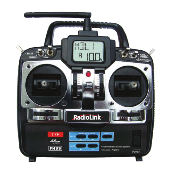
HELI mode: Dual rate (D/R), Idle up, Throttle hold, and Gyro sense can be operated by switch. Two different gyro senses can be set with RadioLink GY100 Gyro on gyro function of this transmitter. Programming features include servo reversing and E.P.A on all channels, dual rates, exponentials, throttle curve, pitch curve, throttle hold, and pit to rudder mixing(REVO). - Page 5 You can connect the sense adjust connector to channel 5 of the receiver to operate the gyro, which has two different senses. Also if you use the RadioLink GY100 Gyro, two different gyro sense settings on the gyro function in this transmitter can be called by this switch.
-
Page 6: Radio Installation
RADIO INSTALLATION Follow these guidelines to properly mount the servos, receiver and battery Make certain the alignment tab on the battery, switch and servo connectors is oriented correctly and “keys” into the corresponding notch in the receiver or connectors before plugging them in. When unplugging connectors, never pull on the wires. - Page 7 Receiver's Antenna Installation: To obtain the best results of function, please refer to the following instructions; 1. The antenna must be kept as straight as possible. Otherwise it will reduce the effective range. 2. Larger models can have large metal objects that can attenuate the RF signal. In this case the antenna should be placed at both sides of the model.
-
Page 8: Receiver And Servo Connections
RECEIVER AND SERVO CONNECTIONS Connect the servos to the receiver to perform the functions indicated: Function Receiver Output Aircraft(ACRO) Helicopter(HELI) Channel Aileron-or-right flaperon-or-right eleven(for Aileron tailless models) Elevator-or-left ruddervator(for V-Tail models) Elevator –or-left elevon( for tailless models) Throttle Throttle Rudder-or-right ruddervator(for V-Tail models) Rudder Retractable landing gear Gyro sensitivity... -
Page 9: Lcd And Programming Controls
Model name The RadioLink T7F-2.4GHz stores model memories for six models. This means all the data (control throws, trims, end points, etc.) for up to six different models can be stored in the transmitter and activated at any time (depending upon which model you choose to fly that day). - Page 10 Transmitter battery voltage Battery ” i con In addition to the model type, the LCD screen also displays the transmitter battery voltage. When the voltage goes below approximately 8.5 Volts the “battery” icon will flash and the lowbattery alarm will continuously beep until the transmitter is turned off. When the low- battery alarm sounds, land immediately your model before losing control.
-
Page 11: Programming The T7F-2.4Ghz Radio
PROGRAMMING THE T7F-2.4GHz RADIO Anytime you wish to view or change any of the current settings in the transmitter, the programming mode must first be entered by, of course, turning on the power, then by pressing the MODE“▲”and“▼” keys simultaneously and holding them down for one second. -
Page 12: Acro/Heli Model Type Select Function
ACRO/HELI Model type select function The Model type select function is used to select the ACRO or HELI mode of model type. ACRO: Powered aircraft memory type (with multiple wing and tail configurations. See Wing mixing type selection for further information,p16) HELI: Helicopter memory type (with two helicopter swashplate type. -
Page 13: D/R Dual Rate And Exponential Settings
Dual Rates / Exponential Settings The aileron, elevator and rudder dual rates on the T7F are simultaneously activated by the dual rate switch. The amount of travel decrease for each control may be set between 0% and 100% of the values set for the end points.(explained in End Point Adjustment on page 13). -
Page 14: Trim Trim Settings
The EPA function is designed to “fine tune” the servo throws in cases where changing the pushrod hookup will not achieve the correct throw. The pushrods should first be connected to the servo arms and control horns so that the correct, or near correct control surface throw will be achieved. -
Page 15: N-Th Normal Throttle Curve
PMIX1/2 Programmable Mixer 1/2 (ACRO only) Unlike the “wing mixing” function (explained later) where the channels to be mixed are factory-set, the T7F-2.4GHz also contains two programmable mix where you, the pilot determine the channels to be mixed. This could be used to correct unwanted flight tendencies (by mixing rudder to aileron, or aileron to rudder for example). -
Page 16: Flpr Flaperon Mixing
5.Press the SELECT key once to display the flashing % sign. Use the DATA “+” key to set the percentage of mixing from -100% to +100% (depending on the direction and distance you wish the slave servo to move). 6.Press SELECT key four times to call the screen for selecting the on/off switch. Then select the switch by pushing DATA “+”... -
Page 17: V-Tl V-Tail Mixing
4. If you need to set aileron differential, press the SELECT key to display the flashing “%” sign. Use the DATA “+” key to set the percentage of aileron differential from -100% to +100% (The “-” direction indicates decreasing amount of movement toward the upward from the aileron surface, while “+”... -
Page 18: Elvn Elevon Mixing
To activate V-tail mixing: 1. Connect the left ruddervator servo to channel 2 (elevator) in the receiver and connect the right ruddervator servo to channel 4 (rudder) in the receiver. 2. Enter the programming mode. Access the “V-TL” screen with the MODE“▲”or“▼” key. You cannot set “V-tail”... -
Page 19: Aux Auxiliary Function
2. Enter the programming mode. Access the “ELVN” screen with the MODE“▲”or“▼” key. You cannot set “Elevon” mixing when “Flaperon” or “V-TL” mixing has already been set. In order to enable “Elevon” mixing, you first need to cancel both “Flaperon” and “V-tail” mixing. 3. -
Page 20: N-Th Normal Throttle Curve
N-TH Normal throttle curve function (HELI only) Used to set throttle curve for normal flight. 5-point throttle curve is utilized to best match the blade collective pitch to the engine RPM for consistent load on the engine. Throttle curve can be adjusted from 0-100% each point. This normal throttle curve creates a basic curve for hovering. -
Page 21: I-Pi Idle-Up Pitch Curve Function
3. Use SELECT key to select the desired curve point. Point 1 is shown initially, which is the throttle stick's all the way downward (slow) position. Point 5 is the throttle stick's all the way upward (hi) position. 4. Press DATA “+” or “-” key to set the servo position. 5. -
Page 22: Revo Pitch - Rudder Mixing Function
Heading-Hold SMM: 21st Century gyro technology. Computer chip technology. Expensive, easier set up, higher durability. Significant decrease in temperature sensitivity. Many include frame rate settings to allow faster response when using specialized digital servos. Examples: RadioLink GY-100: Simpler set up. Ideal for learning aerobatics through 3D... -
Page 23: Swsh Swashplate Types Selection & Swash Afr
Flip the gyro (CH5) switch up and down. This will cause the arrow on the display to point up and down corresponding to the switch position. Press DATA “+” or “-” key to set the gyro gains for both switch up and down position. Gyro gain can be adjust from -100% to +100% Example of sensitivity setting with RadioLink GY-100 Relationship Sensitivity... -
Page 24: Aux Auxiliary Function
To select the swashplate types: 1. Enter the programming mode and use the MODE“▲”or“▼” key to access the “SWSH” function. 2. To select swashplate type press the DATA “+” or “-” key for about two seconds. When you are changing swashplate type to 1-S or 3-S, the 1-S or 3-S on the display flashes slow, becomes rapid,... -
Page 25: Flow Chart (Acro)
FLOW CHART ACRO MODE FUNCTIONS Stick Mode 7-Channel Radio Control System To change the Stick Mode, hold the MODE“▲”and“▼” keys down To enter or leave Programming Press MODE “▲” key to scroll to simultaneously,then turn on the Mode,press MODE“▲”and“▼” previous function menu. transmitter. -
Page 26: Flow Chart (Heli)
FLOW CHART HELI MODE FUNCTIONS Stick Mode 7-Channel Radio Control System To change the Stick Mode, hold the To enter or leave Programming MODE“▲”and“▼” keys down Press MODE “▲” key to scroll to Mode,press MODE“▲”and“▼” simultaneously,then turn on the previous function menu. keys simultaneously for one transmitter. -
Page 27: Othert7F-2.4Ghz Functions
OTHER T7F-2.4GHz FUNCTIONS Trainer switch To utilize the trainer function, the appropriate trainer cord (available separately) and a second RadioLink transmitter (usually provided by your flight instructor or R/C club) will be required. When two radios are connected with the trainer cord, they are both capable of operating the model, but it's usually best for the instructor to hold the radio that has been setup for the plane to be flown (as it is already programmed to fly the model). -
Page 28: Flight Preparation
If a mode is selected that moves the throttle control to the right stick, the throttle detent mechanism will have to be moved as well. Please visit our website (http://www. radiolink.com.cn/doce/download-default.html) and download the file of Manual for changing Mode for 6CH radio for operation details. -
Page 29: Model Data Recording Sheets (Acro)
MODEL DATA RECORDING SHEET (ACRO) (Make copies before using) Model name: Model No. 1• 2 • 3 • 4 • 5 • 6 Model Type: ACRO MENU FUNCTION CH 1 CH 2 CH 3 CH 4 CH 5 CH 6 REVR •... -
Page 30: Model Data Recording Sheets (Heli)
MODEL DATA RECORDING SHEET (HELI) (Make copies before using) Model name: Model No. 1• 2 • 3 • 4 • 5 • 6 Model Type: HELI MENU FUNCTION CH 1 CH 2 CH 3 CH 4 CH 5 CH 6 Servo Reverse REVR •...
Need help?
Do you have a question about the T7F-2.4Ghz and is the answer not in the manual?
Questions and answers