Table of Contents
Advertisement
RadioLink Electronic Ltd
www.radiolink.com
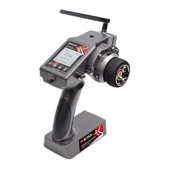
RC6GS
V3
Digital 7-Channel Proportional RC System
Instruction Manual
Adaptable to RC Cars/Boats/Robot
CE FCC RoHS
* Please be kindly noted that this manual will be updated regularly and please visit RadioLink official website
www.radiolink.com to download the latest version.
Advertisement
Table of Contents

Related Manuals for RadioLink RC6GS V3


Summary of Contents for RadioLink RC6GS V3
- Page 1 RC6GS Digital 7-Channel Proportional RC System Instruction Manual Adaptable to RC Cars/Boats/Robot CE FCC RoHS * Please be kindly noted that this manual will be updated regularly and please visit RadioLink official website www.radiolink.com to download the latest version.
- Page 2 RadioLink Electronic Ltd www.radiolink.com Thank you for choosing RadioLink 2.4 GHz 7 channels radio -- RC6GS V3. To fully enjoy the benefits of this product and ensure safety, please read the manual carefully and set up the device as instructed steps.
- Page 3 (2) Changes or modifications not expressly approved by the party responsible for compliance could void the user's authority to operate the equipment. Packing list Items RC6GS V3 Transmitter R7FG Receiver XT60 Model Battery Voltage Telemetry Cable Lanyard...
-
Page 4: Table Of Contents
RadioLink Electronic Ltd www.radiolink.com CONTENTS I. RC6GS V3 Remote Control System ........................5 1.1 Transmitter ..............................5 1.2 Receiver R7FG(Standard Pack) ....................... 6 1.2.1 R7FG Specification ..........................6 1.2.2 Receiver Installation and Binding ......................7 1.2.3 Working Mode ............................7 1.2.4 Gyro Setup .............................8 1.2.5 Signal/RSSI Real-time Return ....................... - Page 5 3.5 Dual Rate Function on RC6GS V3 ......................39 3.6 EPA Function on RC6GS V3 ........................39 3.7 Set Different ALARM for 30 Different Models on RC6GS V3 ..............39 3.8 ID Seed Function on RC6GS V3 ......................39 3.9 Cruise Control Function on RC6GS V3 ....................39 3.10 Head Track Function on RC6GS V3 .....................39...
-
Page 6: Rc6Gs V3 Remote Control System
The same FHSS spread spectrum and 67 channels pseudo random frequency sequence hopping of AT9S Pro makes RC6GS V3 have superior anti-interference ability both at the same frequency band and different frequency bands. Control distance is up to 600 meters. -
Page 7: Receiver R7Fg(Standard Pack)
Compatible Receiver: R7FG(Standard), R8FG, R6FG,R6F, R8EF, R8F, R4FGM,R4F Battery Tray Dimension: 89*59*25mm (3.5”*2.32”*0.98") 1.2 Receiver R7FG(Standard Pack) RC6GS V3, come with R7FG, 2.4GHz 7 channels receiver, splash-proof, gyro integrated and high voltage servo supported. 1.2.1 R7FG Specification Size: 35*22*13 mm(1.37*0.86*0.5") ... -
Page 8: Receiver Installation And Binding
Note 1. The binding between your R7FG and RC6GS V3 is already complete by default. Just need to make sure there is the solid light of R7FG and the signal tower in the transmitter. 2. NO gyro by default as factory setting. Since integrated gyro in R7FG will self-check, it is very imporant to remain R7FG still when powering it on. -
Page 9: Gyro Setup
RadioLink Electronic Ltd www.radiolink.com R7FG Working Mode Gyro + SBUS Working Mode PWM Mode SBUS Mode Gyro mode Note Mode Telemetry Port of Model Battery Voltage ( + - ) Telemetry TELEMETRY port is only for 2S-8S battery voltage telemetry. The port cannot be used to power the receiver. -
Page 10: Signal/Rssi Real-Time Return
Note: The 'RATE: RPM' and 'T: NULL' telemetry functions are still under development. If there are new developments, we will announce them to the RadioLink official website as soon as possible. 1.2.6 Telemetry of Model Battery and Receiver Voltage Besides the return of RSSI, receiver voltage, model battery voltage (maximum up to 8S lithium battery) can also be returned in real time. -
Page 11: Rc6Gs V3 Functions
RadioLink Electronic Ltd www.radiolink.com II. RC6GS V3 Functions 2.1 Display on LCD Screen Basic Operation... - Page 12 RadioLink Electronic Ltd www.radiolink.com When you power on the transmitter, LCD screen shows Model Name, Transmitter Name, Transmitter Voltage, Steering Trim, Throttle Trim, Model Voltage, Subsidiary Model ID, Returned Signal. Note The Subsidiary ID won’t display until the function is activated in the menu ID SEED.
-
Page 13: Language "Language
(4) Press “Enter” button, the desired language is selected, Numbers at the bottom means the current firmware version. Eg. V6.6.7 in above picture. 2.3 Model Select "MODEL" RC6GS V3 can store model memories for 30 models. Use this function to call a new model. Each model can independently set the parameters of each function. -
Page 14: Steering Exponential "Stexp
End point adjustment Long press "Exit" and "Enter" button simultaneously for one second to enter the function menu of RC6GS V3. Press "Inc(+)" button at the bottom of the screen to move the cursor to "3. EPA", and then press "... -
Page 15: Steering Speed "Stspd
RadioLink Electronic Ltd www.radiolink.com will blink, then you can press “Dec(-) ”or “Inc(+)”button to adjust the value and the curve of the rate shown in the figure will change correspondingly. (Note: In the interface of adjusting the value, return to the initial value "0%" by pressing “Dec(-)” and“Inc(+)”... - Page 16 RadioLink Electronic Ltd www.radiolink.com Throttle curve adjustment Adjustment method for CRV curve Setup Items Mode: ON/OFF RATE: 0%~100% 1. Enter the function menu and use“ Dec(-) ” or “ Inc(+) ”button to access THEXP function. Select “FWD-CRV” function. 2. Press “Dec(-)” or “Inc(+)” button to select curve points 1~5 for curve point adjustment that you want, from the graph you will clearly see the changes you have made.
-
Page 17: Throttle Speed "Thspd
RadioLink Electronic Ltd www.radiolink.com 0~+100: sensitive braking Brake side adjustment (select BRK) (1) Press “Enter” key, the current BRK value will blink, use “Inc(+)” button to adjust the + side when you want to quicker the rise and use“Dec(-)” button to adjust the - side when you want to make the rise milder. -
Page 18: Function "A.b.s
RadioLink Electronic Ltd www.radiolink.com LOW: Low side range speed adjustment HIGH: High side range speed adjustment TGP1: Low and medium speed switching point Adjustment range LOW: 0~100 HIGH: 0~100 At 100, there is no delay TGP1: 0~100 (1) Enter the function menu and use “Dec(-)”or “Inc(+) ” button to access THSPD function. - Page 19 RadioLink Electronic Ltd www.radiolink.com release. When set to 0, the ABS function is not Performed. When set to 50, the servo returns 50% (1/2)of the trigger operation amount and when set to 100, the servo returns to the neutral position.
- Page 20 RadioLink Electronic Ltd www.radiolink.com Press “Enter” button, the adjusted value stops blinking, now the value has been set. - The smaller the set value, the faster the pulse speed. Cycle speed (CYC) 0 ~ 30 Initial value: 5 (4) Operation point setup Select setting item "TGP"...
-
Page 21: Throttle Acceleration "Accel
RadioLink Electronic Ltd www.radiolink.com Steering mixing (STM) OFF, N10 ~ N100, E10 ~ E100 Initial value: OFF When steering mixing is set and steering operation enters the set range, "*" is displayed in front of the number. When mixing is OFF, the A.B.S function can operate over the entire steering range. -
Page 22: Idle-Up "Idlup
RadioLink Electronic Ltd www.radiolink.com 2.11 Idle-Up "IDLUP" 2.11.1 Idle up at engine start Use this function to improve the starting characteristics of the engine by raising the idling speed when starting the engine of a gas powered car. Idle-Up rate (RATE) -
Page 23: Channel Reverse "Reverse
RadioLink Electronic Ltd www.radiolink.com CH3: Channel3(VR) CH4: Channel4(SWA) CH5: Channel5(SWB) CH6: Channel6(SWC) CH7: Channel7(SWD) Sub-trim ST: -100~0~+100 TH: -100~0~+100 CH3: -100~0~+100 CH4: -100~0~+100 CH5: -100~0~+100 CH6: -100~0~+100 CH7: -100~0~+100 Initial value : 0 (1) Enter the function menu and use “Dec(-)”or “Inc(+)” button to access SUBTRIM function. -
Page 24: Steering/Throttle Dual Rate "D/R
(1) Long press "Exit" and "Enter" button simultaneously for one second to enter the function menu of RC6GS V3. Press "Inc(+)" button at the bottom of the screen to move the cursor to "13. D/R", and then press " Enter” button to enter the function setting interface. -
Page 25: Brake Side Adjustment "Atl
RadioLink Electronic Ltd www.radiolink.com Push SWB/SWC switch to the lower position (DOWN will be displayed in the upper right corner of the screen), the method is the same as above; 2. If you set SWA or SWD switch. Press it to one dual rate value, and release it to another dual rate value. - Page 26 RadioLink Electronic Ltd www.radiolink.com RIGN: Mixing rate (Right side) MST: Master channel SLV: Slave channel (1) Master channel Channel selection (MST) ST, TH, CH3, CH4, CH5, CH6, CH7 Initial value: ST Select setup item"MST" by pressing “Dec(-)” or“Inc(+)”button, press“ Enter ” button, the initial master channel will blink.
-
Page 27: Mix Control Setup
Same as ONE TO TWO mix control. Dual Mix Control: As controlling dual-engine vehicles drive forward/backward and turn left/right, two mix controls at the same time are needed. RadioLink RC6GS V3 has two programmable mix controls. Reverse Setup before Mix Control Setup Before setting the mix controls, please check if the reverses working correctly by testing its wheel and throttle. - Page 28 1. Throttle Reverse:NOR-REV Hold RC6GS V3 as the below pic. Normally, pull the throttle, the right track should be moving forward while push the throttle and the right track should be backward. Pull the throttle,right track moves forward,left track remains still If pulling the throttle and the left track moves backward;...
- Page 29 RadioLink Electronic Ltd www.radiolink.com Turn the wheel clockwise, the left track moves forward,the right track remains still If turning the wheel right and the right track moves backward; Or turning the wheel left and the right track moves forward, meaning the initial steering is reversed and needs to be set. Please refer to the “button operation”and get into below interface to complete the setup.
- Page 30 RadioLink Electronic Ltd www.radiolink.com Throttle mix steering setup completed, both tracks moves forward when pulling the throttle 2. Steering mix Throttle:Tracked vehicles turning left/right As tracked vehicles turning left/right is controlled by steering, steering leads throttle in the mix control. That is, Master-Steering, Slave-Throttle.
-
Page 31: Auxiliary Channel "Aux-Ch
Factory default name: MODEL1 (1) Long press "Exit" and "Enter" button simultaneously for one second to enter the function menu of RC6GS V3. Press "Inc(+)" button at the bottom of the screen to move the cursor to "18. NAME". (2) Press “Enter” button to get into NAME function interface, the first character of current name will blink, and the blinking character can be reset. -
Page 32: Alarm(Safety Alarm For Low Voltage And Signal Strength )
RadioLink Electronic Ltd www.radiolink.com or “Inc(+)” button to choose the character you desired.Press“Enter” button again, the next character of current name will blink. Reset other characters of current name in same manner. (3) After accomplishment of naming, all characters of current name will stop blinking, the new name will be stored automatically. -
Page 33: Gyro Sensitivity "Gyro
RadioLink Electronic Ltd www.radiolink.com 2.20 Gyro Sensitivity “GYRO” This function is available to set gyro sensitivity and VR mixing ON or OFF. When MIX set OFF, gyro is disabled while when MIX set ON, you can adjust gyro sensitivity STD or VR. STD is adjusted on screen and VR is default CH3. -
Page 34: Subsidiary Id "Id Seed
ID codes of this transmitter. For example, RC6GS V3 has completed the binding with 10 different boats and the setup of respective parameters. Turn on the ID SEED function, select ID.1 boat and drive it to the central of water but it stops working unexpectedly. - Page 35 3 axis track mode: If you need to connect FPV goggles with 3 axis track function to the DSC port of RC6GS V3, please set the mode to: 3 axis track. When the DSC mode of RC6GS V3 is selected as 3 axis track, the DSC port outputs in channel 5, channel 6 and channel 7 by default, which are used to control the pan, tilt and yaw servos.
-
Page 36: Timer Setting "Timer
Long press "Exit" and "Enter" button simultaneously for one second to enter the function menu of RC6GS V3. Press "Inc(+)" button at the bottom of the screen to move the cursor to "24. TIMER", and then press " Enter” button to enter the function setting interface. -
Page 37: Factory Reset "Reset
III. Tutorials 3.1 Firmware Update of RC6GS V3 Video tutorial:https://www.youtube.com/watch?v=XLyTnSlou-4 Firmware update steps: 1. Check the firmware version in the basic menu--LANGUAGE before firmware update. 2. Download the newest firmware in RadioLink official website. (https://www.radiolink.com/rc6gsv3_firmware) - Page 38 RadioLink Electronic Ltd www.radiolink.com 3. Power off RC6GS V3. And then connect it to the computer with a USB cable. 4. Power on RC6GS V3. Note: The screen won’t light up at this time. 5. Don’t need to format the Drive of the transmitter. Just copy the newest firmware and paste it into the Drive.
- Page 39 RadioLink Electronic Ltd www.radiolink.com 3. Push the throttle trigger all the way forward and then push it all the way back. The value of the calibration interface will change at the same time. 4. Turn the wheel and VR knob fully clockwise and then fully counterclockwise. The value of the calibration interface will change at the same time.
- Page 40 3.10 Head Track Function on RC6GS V3 Video tutorial:https://www.youtube.com/watch?v=0H5zo-yfWdw 3.11 Set up FPV Monitor on RC6GS V3 Video tutorial:https://www.youtube.com/watch?v=FP5nGmbiL6g 3.12 TX Low Power & Battery Power Supply Options of RC6GS V3 Video tutorial:https://www.youtube.com/watch?v=ppcpfiuq8b4 3.13 Connect RC6GS V3 to TBS Crossfire Video tutorial:https://www.youtube.com/watch?v=6vt5QexQSQs 3.14 LK-A/LK-D Button Setup on RC6GS V3...
Need help?
Do you have a question about the RC6GS V3 and is the answer not in the manual?
Questions and answers
lier la RC6GS à des voitures sans acces au récepteur
You cannot bind the RadioLink RC6GS V3 to a car without access to the receiver. Binding requires access to the receiver to complete the pairing process with the transmitter.
This answer is automatically generated
1) Why should i have to select reverse on the controller to make throttle work correctly? 2) When i plug the battery in the motor runs full throttle until i pull the trigger to stop it.