Table of Contents
Advertisement
Quick Links
IRS-100-ULT3 Railway Surveillance System
MODEL:
IRS-100-ULT3
Railway Surveillance System with Intel® Core™ i5-6300U CPU,
4 GB DDR4L Memory Preinstalled, Dual M12 GbE LAN Port,
CFast, Dual SIM Card Slot, One DVI-D, One VGA,
Dual 2.5" SATA HDD/SSD Bay, EN 50155 Compliant
User Manual
Page i
Rev. 1.00 – April 19, 2017
Advertisement
Table of Contents

Related Manuals for IEI Technology IRS-100-ULT3


Summary of Contents for IEI Technology IRS-100-ULT3
- Page 1 IRS-100-ULT3 Railway Surveillance System MODEL: IRS-100-ULT3 Railway Surveillance System with Intel® Core™ i5-6300U CPU, 4 GB DDR4L Memory Preinstalled, Dual M12 GbE LAN Port, CFast, Dual SIM Card Slot, One DVI-D, One VGA, Dual 2.5” SATA HDD/SSD Bay, EN 50155 Compliant...
- Page 2 IRS-100-ULT3 Railway Surveillance System Revision Date Version Changes April 19, 2017 1.00 Initial release Page ii...
- Page 3 IRS-100-ULT3 Railway Surveillance System Copyright COPYRIGHT NOTICE The information in this document is subject to change without prior notice in order to improve reliability, design and function and does not represent a commitment on the part of the manufacturer. In no event will the manufacturer be liable for direct, indirect, special, incidental, or consequential damages arising out of the use or inability to use the product or documentation, even if advised of the possibility of such damages.
- Page 4 IRS-100-ULT3 Railway Surveillance System Federal Communication Commission Interference Statement This equipment has been tested and found to comply with limits for a class A digital device, pursuant to part 15 of the FCC Rules. These limits are designed to provide reasonable protection against harmful interference in a residential installation.
- Page 5 IRS-100-ULT3 Railway Surveillance System Manual Conventions WARNING Warnings appear where overlooked details may cause damage to the equipment or result in personal injury. Warnings should be taken seriously. CAUTION Cautionary messages should be heeded to help reduce the chance of losing data or damaging the product.
- Page 6 IRS-100-ULT3 Railway Surveillance System Table of Contents 1 INTRODUCTION......................1 1.1 O ........................2 VERVIEW 1.2 F ........................2 EATURES 1.3 F ......................3 RONT ANEL 1.4 R ....................... 4 ANEL 1.5 B ......................4 OTTOM ANEL 1.6 S .................... 5...
- Page 7 IRS-100-ULT3 Railway Surveillance System 3.10.2 DC Power Input Connector ................25 3.10.3 Digital I/O Terminal Block................26 3.10.4 DVI-D Connector................... 27 3.10.5 LAN Connectors..................... 28 3.10.6 RS-232/422/485 Serial Ports ................. 28 3.10.7 USB 2.0 Connector ..................29 3.10.8 USB 3.0 Ports....................29 3.10.9 VGA........................
- Page 8 IRS-100-ULT3 Railway Surveillance System 4.3.9 USB Configuration................... 54 4.3.10 ICP Board ...................... 55 4.4 C ........................56 HIPSET 4.4.1 System Agent (SA) Configuration ..............57 4.4.1.1 Graphics Configuration................58 4.4.1.2 Memory Configuration ................60 4.4.2 PCH-IO Configuration ..................61 4.4.2.1 PCI Express Configuration ............... 62 4.5 S...
- Page 9 IRS-100-ULT3 Railway Surveillance System B.1 S ..................... 86 AFETY RECAUTIONS B.1.1 General Safety Precautions ................86 B.1.2 Anti-static Precautions ..................87 B.1.3 Product Disposal ..................... 88 B.2 M ............88 AINTENANCE AND LEANING RECAUTIONS B.2.1 Maintenance and Cleaning................88 B.2.2 Cleaning Tools ....................89 C WATCHDOG TIMER ....................
- Page 10 IRS-100-ULT3 Railway Surveillance System List of Figures Figure 1-1: IRS-100-ULT3 Railway Surveillance System ............2 Figure 1-2: Front Panel ........................3 Figure 1-3: Rear Panel........................4 Figure 1-4: Bottom View ........................4 Figure 1-5: Dimensions (unit: mm) ....................7 Figure 3-1: Bottom Cover Retention Screws ................15 Figure 3-2: AT/ATX Mode Selection Switch Location ...............16...
- Page 11 IRS-100-ULT3 Railway Surveillance System Figure 3-26: Mobile AP–Connection ...................34 Figure 5-1: SO-DIMM Slot Locations ..................69 Figure 5-2: SO-DIMM Installation ....................70 Figure 6-1: Main Board Layout Diagram (Front Side) ...............72 Figure 6-2: Main Board Layout Diagram (Solder Side) .............73 Page xi...
- Page 12 IRS-100-ULT3 Railway Surveillance System List of Tables Table 1-1: Technical Specifications....................6 Table 2-1: Packing List.........................10 Table 2-2: Optional Items......................11 Table 3-1: DVI/CRT Selection Switch Settings ................18 Table 3-2: Flash Descriptor Security Override Jumper Settings..........19 Table 3-3: Audio Connector Pinouts ..................25 Table 3-4: DC Power Input Connector Pinouts................25...
- Page 13 IRS-100-ULT3 Railway Surveillance System BIOS Menus BIOS Menu 1: Main ........................38 BIOS Menu 2: Advanced ......................39 BIOS Menu 3: ACPI Configuration ....................40 BIOS Menu 4: RTC Wake Settings ....................41 BIOS Menu 5: F81866 Super IO Configuration ................42 BIOS Menu 6: Serial Port n Configuration Menu...............43 BIOS Menu 7: F81866 Hardware Monitor ...................46...
-
Page 14: Introduction
IRS-100-ULT3 Railway Surveillance System Chapter Introduction Page 1... -
Page 15: O Verview
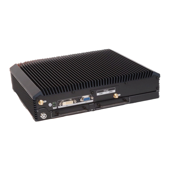
At the heart of the system is the Intel® Core™ i5-6300U processor, offering low power in a powerful package. The IRS-100-ULT3 can work under extreme temperature (-40ºC ~ 70ºC) and accepts a wide range of DC power input (24 V ~ 110 V). With the optional Wi-Fi and 3G modules, the IRS-100-ULT3 can ensure smooth network connectivity. -
Page 16: Figure 1-2: Front Panel
IRS-100-ULT3 Railway Surveillance System One CFast card slot Two M12 GbE LAN ports Two external SIM card slots Two DB-9 RS-232/422/485 serial ports One 8-bit digital I/O terminal block One M12 USB 2.0 port One M12 audio port, supporting line-in and line-out Two USB 3.0 ports (Type A) -
Page 17: Figure 1-3: Rear Panel
IRS-100-ULT3 Railway Surveillance System 1.4 Rear Panel An overview of the rear panel is shown in Figure 1-3 below. Figure 1-3: Rear Panel 1.5 Bottom Panel The bottom panel has the mounting screw holes for the mounting brackets. Figure 1-4: Bottom View... - Page 18 IRS-100-ULT3 Railway Surveillance System 1.6 System Specifications The IRS-100-ULT3 technical specifications are listed in Table 1-1. System CPU (SoC) Intel® Core™ i5-6300U (TDP: 15 W) 2 x 260-pin DDR4L SO-DIMM slots (system max. 32 GB) Memory Preinstalled with one 4 GB DDR4L SO-DIMM 2 x 2.5”...
-
Page 19: Table 1-1: Technical Specifications
IRS-100-ULT3 Railway Surveillance System 1 x 8-bit digital I/O (1.5 kV isolation protection, 10-pin terminal block) 1 x VGA connector 1 x USB 2.0 (M12 A-coded) 2 x USB 3.0 (Type A) 2 x HDD/SSD LED LED Indicators 2 x SIM LED... -
Page 20: Figure 1-5: Dimensions (Unit: Mm)
IRS-100-ULT3 Railway Surveillance System 1.7 Dimensions The dimensions are shown below. Figure 1-5: Dimensions (unit: mm) Page 7... -
Page 21: Unpacking
IRS-100-ULT3 Railway Surveillance System Chapter Unpacking Page 8... -
Page 22: P Recautions
Only handle the edges of the PCB: Don't touch the surface of the motherboard. Hold the motherboard by the edges when handling. 2.2 Unpacking Precautions When the IRS-100-ULT3 is unpacked, please do the following: Follow the anti-static guidelines above. Make sure the packing box is facing upwards when opening. -
Page 23: Table 2-1: Packing List
If any of the components listed in the checklist below are missing, do not proceed with the installation. Contact the IEI reseller or vendor the IRS-100-ULT3 was purchased from or contact an IEI sales representative directly by sending an email to ales@ieiworld.com. -
Page 24: Table 2-2: Optional Items
M12 X-coded cable for Ethernet (P/N: 32013-003400-100-RS) M12 A-coded cable for line-in and line-out (P/N: 32007-005400-100-RS) OS image with Windows® Embedded Standard 7 E 64-bit for IRS-100-ULT3, DVD-ROM, RoHS (P/N: IRS-100-ULT3-WES7E64-R10) 1T1R Wi-Fi module kit, Wi-Fi 802.11a/b/g/n/ac with Bluetooth v4.0/3.0+HS (assemble-to-order) (P/N: IRS-100-WIFI-KIT02-R10) -
Page 25: Installation
IRS-100-ULT3 Railway Surveillance System Chapter Installation Page 12... -
Page 26: P Recautions
Electrostatic discharge (ESD) can cause serious damage to electronic components, including the IRS-100-ULT3. Dry climates are especially susceptible to ESD. It is therefore critical that whenever the IRS-100-ULT3 is accessed internally, or any other electrical component is handled, the following anti-static precautions are strictly adhered to. - Page 27 IRS-100-ULT3. The IRS-100-ULT3’s cooling vents must not be obstructed by any objects. Blocking the vents can cause overheating of the IRS-100-ULT3. Leave at least 5 cm of clearance around the IRS-100-ULT3 to prevent overheating. Grounding: The IRS-100-ULT3 should be properly grounded. The voltage feeds must not be overloaded.
-
Page 28: Figure 3-1: Bottom Cover Retention Screws
IRS-100-ULT3 Railway Surveillance System Figure 3-1: Bottom Cover Retention Screws Gently open the bottom cover. Step 3: Step 0: Page 15... -
Page 29: At/Atx Power Mode Selection
Please refer to Section 3.4 for details. 3.5.1 AT/ATX Power Mode Selection AT or ATX power mode can be configured on the IRS-100-ULT3. The selection is made through an AT/ATX switch located on the rear panel (Figure 3-2). -
Page 30: Clearing Cmos
IRS-100-ULT3 Railway Surveillance System 3.5.2 Clearing CMOS If the IRS-100-ULT3 fails to boot due to improper BIOS settings, the clear CMOS button clears the CMOS data and resets the system BIOS information. To do this, push the clear CMOS button for three seconds, and then restart the system. The clear CMOS button location is shown in F igure 3-3. -
Page 31: Dvi/Crt Selection Switch
IRS-100-ULT3 Railway Surveillance System 3.5.3 DVI/CRT Selection Switch To connect a CRT monitor to the DVI-D connector, the user has to set the DVI/CRT selection switch to CRT position. Refer to Figure 3-4 and Table 3-1 for the switch location and settings. -
Page 32: Flash Descriptor Security Override
IRS-100-ULT3 Railway Surveillance System 3.5.4 Flash Descriptor Security Override The Flash Descriptor Security Override jumper (J_FLASH1) allows to enable or disable the ME firmware update. Refer to Figure 3-5 and Table 3-2 for the jumper location and settings. Setting Description... -
Page 33: Figure 3-6: Unlocking The Hdd/Ssd Trays
IRS-100-ULT3 Railway Surveillance System 3.6 HDD/SSD Installation The IRS-100-ULT3 comes with two 2.5” SATA HDD/SSD bays. To install an HDD/SSD, please follow the steps below. Use the key that came with the IRS-100-ULT3 package to unlock the HDD/SSD Step 1: trays (Figure 3-6). -
Page 34: Figure 3-8: Hdd/Ssd Retention Screws
IRS-100-ULT3 Railway Surveillance System Figure 3-8: HDD/SSD Retention Screws Carefully insert the HDD/SSD tray into the slot on the front panel (Figure 3-9). Step 4: Make sure the SATA connector on the HDD/SSD is securely connected to the SATA connector inside the chassis. -
Page 35: I Nstallation
IRS-100-ULT3 Railway Surveillance System 3.7 CFast Card Installation To install a CFast card, follow the instructions below. The CFast card slot is protected by a metal cover. Remove the retention screw that Step 1: secured the metal cover to the chassis to expose the CFast card slot (Figure 3-11). -
Page 36: Figure 3-13: Sim Card Slot Locations
WARNING: Please install a mini-SIM (2FF or Standard SIM) card for proper network connection. The IRS-100-ULT3 has two SIM card slots on the front panel. To install a SIM card, follow the instructions below. NOTE: The IRS-100-ULT3 provides an application for setting which SIM card to use. -
Page 37: Figure 3-14: Mounting Bracket Retention Screws
IRS-100-ULT3 Railway Surveillance System 3.9 Mounting the System To mount the IRS-100-ULT3 onto a wall or some other surface using the two mounting brackets, please follow the steps below. Turn the IRS-100-ULT3 over. Step 1: Align the four retention screw holes in each bracket with the retention screw Step 2: holes on the sides of the bottom surface. -
Page 38: C Onnectors
Table 3-3: Audio Connector Pinouts Figure 3-15: Audio Connector Pinout Location 3.10.2 DC Power Input Connector The IRS-100-ULT3 has an M12 A-coded, 24 V ~ 110 V DC power input connector. The pinouts for the power input connector are listed in Table 3-4. Description... -
Page 39: Digital I/O Terminal Block
IRS-100-ULT3 Railway Surveillance System Figure 3-16: DC Power Input Connector Pinout Location 3.10.3 Digital I/O Terminal Block The digital I/O terminal block provides programmable input and output for external devices. The pinouts for the digital I/O terminal block are listed in the table below. -
Page 40: Dvi-D Connector
IRS-100-ULT3 Railway Surveillance System 3.10.4 DVI-D Connector The Digital Visual Interface (DVI) connector connects to a high-speed, high-resolution digital display. NOTE: To connect a CRT monitor to the DVI-D connector, the user has to set the DVI/CRT selection switch to CRT position. Please refer to Section 3.5.3 for detailed information. -
Page 41: Lan Connectors
Table 3-7: LAN Connector Pinouts Figure 3-19: LAN Connector Pinout Location 3.10.6 RS-232/422/485 Serial Ports The IRS-100-ULT3 has two DB-9 RS-232/422/485 serial ports on the rear panel for serial devices. The pinouts for the serial port connector are shown in Table 3-8. Description... -
Page 42: Usb 2.0 Connector
USBN Table 3-9: USB 2.0 Connector Pinouts Figure 3-21: USB 2.0 Connector Pinout Location 3.10.8 USB 3.0 Ports The IRS-100-ULT3 has two USB 3.0 ports. The pinouts for the USB 3.0 port are listed in Table 3-10. Description Description Page 29... -
Page 43: Figure 3-22: Usb 3.0 Port Pinout Locations
Figure 3-22: USB 3.0 Port Pinout Locations 3.10.9 VGA The IRS-100-ULT3 has a female DB-15 VGA connector on the front panel. The VGA connector is connected to a CRT or VGA monitor. The pinouts for the VGA connector are listed in Table 3-11. -
Page 44: Power-On Procedure
To power-on the IRS-100-ULT3 please follow the steps below: Connect the power source to the power input connector of the IRS-100-ULT3 Step 1: (Figure 3-24). The IRS-100-ULT3 accepts 24 V ~ 110 V DC power input. Figure 3-24: Power Connector Page 31... -
Page 45: D River I Nstallation
Visit the IEI website or contact technical support for the latest updates. All the drivers for the IRS-100-ULT3 are on the utility CD that came with the system. The following drivers can be installed on the system:... -
Page 46: Mobile Ap
Insert the utility CD into a CD drive connected to the system and install all of the necessary drivers for the IRS-100-ULT3. 3.13 Mobile AP IEI provides an application tool, Mobile AP, for the users of the IRS-100-ULT3 with WWAN module installed to manage mobile network. 3.13.1 Installation To install this application tool, please locate the WLAN folder in the utility CD. -
Page 47: Usage
IRS-100-ULT3 Railway Surveillance System 3.13.2 Usage To launch the application tool, double click the MobileAP icon on the Windows desktop. The user interface appears as shown in Figure 3-26. The functions are described below. Figure 3-26: Mobile AP–Connection Sim card switch: Select a SIM card to designate a SIM card to use or click the Refresh SIM status button to let the system detect automatically. - Page 48 IRS-100-ULT3 Railway Surveillance System Chapter BIOS Page 35...
-
Page 49: I Ntroduction
IRS-100-ULT3 Railway Surveillance System 4.1 Introduction The BIOS is programmed onto the BIOS chip. The BIOS setup program allows changes to certain system settings. This chapter outlines the options that can be changed. NOTE: Some of the BIOS options may vary throughout the life cycle of the product and are subject to change without prior notice. -
Page 50: Getting Help
IRS-100-ULT3 Railway Surveillance System Function Page Up key Move to the previous page Page Dn key Move to the next page Main Menu – Quit and not save changes into CMOS Esc key Status Page Setup Menu and Option Page Setup Menu -- Exit current... -
Page 51: Main
IRS-100-ULT3 Railway Surveillance System 4.2 Main The Main BIOS menu (BIOS Menu 1) appears when the BIOS Setup program is entered. The Main menu gives an overview of the basic system information. Aptio Setup Utility – Copyright (C) 2016 American Megatrends, Inc. -
Page 52: A Dvanced
IRS-100-ULT3 Railway Surveillance System The Main menu has two user configurable fields: System Date [xx/xx/xx] Use the System Date option to set the system date. Manually enter the day, month and year. System Time [xx:xx:xx] Use the System Time option to set the system time. Manually enter the hours, minutes and seconds. -
Page 53: Acpi Settings
IRS-100-ULT3 Railway Surveillance System 4.3.1 ACPI Settings The ACPI Settings menu (BIOS Menu 3) configures the Advanced Configuration and Power Interface (ACPI) options. Aptio Setup Utility – Copyright (C) 2016 American Megatrends, Inc. Advanced ACPI Settings Select the highest ACPI... -
Page 54: Rtc Wake Settings
IRS-100-ULT3 Railway Surveillance System 4.3.2 RTC Wake Settings The RTC Wake Settings menu (BIOS Menu 4) enables the system to wake at the specified time. Aptio Setup Utility – Copyright (C) 2016 American Megatrends, Inc. Advanced Wake system with Fixed Time... -
Page 55: F81866 Super Io Configuration
IRS-100-ULT3 Railway Surveillance System Wake up hour Wake up minute Wake up second After setting the alarm, the computer turns itself on from a suspend state when the alarm goes off. 4.3.3 F81866 Super IO Configuration Use the F81866 Super IO Configuration menu (BIOS Menu 5) to set or change the configurations for the serial ports. -
Page 56: Serial Port N Configuration
IRS-100-ULT3 Railway Surveillance System 4.3.3.1 Serial Port n Configuration Use the Serial Port n Configuration menu (BIOS Menu 6) to configure the serial port n. Aptio Setup Utility – Copyright (C) 2016 American Megatrends, Inc. Advanced Serial Port n Configuration... - Page 57 IRS-100-ULT3 Railway Surveillance System Serial Port I/O port address is 3F8h and the interrupt IO=3F8h; address is IRQ3, 4, 5, 6, 7, 9, 10, 11, 12 IRQ=3, 4, 5, 6, 7, 9, 10, 11, 12 Serial Port I/O port address is 2F8h and the interrupt IO=2F8h;...
- Page 58 IRS-100-ULT3 Railway Surveillance System Change Settings [Auto] Use the Change Settings option to change the serial port IO port address and interrupt address. The serial port IO port address and interrupt address Auto EFAULT are automatically detected. Serial Port I/O port address is 2F8h and the interrupt IO=2F8h;...
-
Page 59: F81866 Hardware Monitor
IRS-100-ULT3 Railway Surveillance System Serial Port Mode [RS232] Use the Device Mode option to select the Serial Port 2 signaling mode. Serial Port 2 signaling mode is RS-232 RS232 EFAULT Serial Port 2 signaling mode is RS-422 RS422 Serial Port 2 signaling mode is RS-485 RS485 4.3.4 F81866 Hardware Monitor... -
Page 60: Smart Fan Mode Configuration
IRS-100-ULT3 Railway Surveillance System 4.3.4.1 Smart Fan Mode Configuration Use the Smart Fan Mode Configuration submenu (BIOS Menu 8) to configure fan temperature and speed settings. Aptio Setup Utility – Copyright (C) 2016 American Megatrends, Inc. Advanced Smart Fan Mode Configuration... -
Page 61: Iwdd H/W Monitor
IRS-100-ULT3 Railway Surveillance System 4.3.5 iWDD H/W Monitor The iWDD H/W Monitor menu (BIOS Menu 9) contains the fan configuration submenus and displays operating temperature, fan speed and system voltages. Aptio Setup Utility – Copyright (C) 2016 American Megatrends, Inc. -
Page 62: Smart Fan Mode Configuration
IRS-100-ULT3 Railway Surveillance System 4.3.5.1 Smart Fan Mode Configuration Use the Smart Fan Mode Configuration submenu (BIOS Menu 8) to configure fan temperature and speed settings. Aptio Setup Utility – Copyright (C) 2016 American Megatrends, Inc. Advanced Smart Fan Mode Configuration... -
Page 63: Cpu Configuration
IRS-100-ULT3 Railway Surveillance System Auto mode fan start PWM Use the + or – key to change the Auto mode fan start PWM value. Enter a decimal number between 1 and 100. Auto mode fan slope PWM Use the + or – key to change the Auto mode fan slope PWM value. Enter a decimal number between 1 and 8. - Page 64 IRS-100-ULT3 Railway Surveillance System Hyper-threading [Enabled] Use the Hyper-threading option to enable or disable the CPU hyper threading function. Disables the use of hyper threading technology Disabled Enables the use of hyper threading technology Enabled EFAULT Active Processor Cores [All] Use the Active Processor Cores option to enable numbers of cores in the processor package.
-
Page 65: Sata Configuration
IRS-100-ULT3 Railway Surveillance System 4.3.7 SATA Configuration Use the SATA Configuration menu (BIOS Menu 12) to change and/or set the configuration of the SATA devices installed in the system. Aptio Setup Utility – Copyright (C) 2016 American Megatrends, Inc. Advanced... -
Page 66: Nvme Configuration
IRS-100-ULT3 Railway Surveillance System NOTE: Before accessing the RAID configuration utility, ensure to set the Option ROM Messages BIOS option in the Boot menu to Force BIOS. This is to allow the “Press <CTRL+I> to enter Configuration Utility……” message to appear during POST. Press Ctrl+I when prompted to enter the RAID configuration utility. -
Page 67: Usb Configuration
IRS-100-ULT3 Railway Surveillance System 4.3.9 USB Configuration Use the USB Configuration menu (BIOS Menu 14) to read USB configuration information and configure the USB settings. Aptio Setup Utility – Copyright (C) 2016 American Megatrends, Inc. Advanced USB Configuration Enables Legacy USB support. -
Page 68: Icp Board
IRS-100-ULT3 Railway Surveillance System 4.3.10 ICP Board Use the ICP Board menu (BIOS Menu 15) to show detailed setup items. Aptio Setup Utility – Copyright (C) 2016 American Megatrends, Inc. Advanced ICP show setup Items [Disabled] ICP show setup Items... -
Page 69: C Hipset
IRS-100-ULT3 Railway Surveillance System 4.4 Chipset Use the Chipset menu (BIOS Menu 16) to access the PCH-IO and System Agent (SA) Subsystem configuration menus. WARNING! Setting the wrong values for the Chipset BIOS selections in the Chipset BIOS menu may cause the system to malfunction. -
Page 70: System Agent (Sa) Configuration
IRS-100-ULT3 Railway Surveillance System 4.4.1 System Agent (SA) Configuration Use the System Agent (SA) Configuration menu (BIOS Menu 17) to configure the System Agent (SA) parameters. Aptio Setup Utility – Copyright (C) 2016 American Megatrends, Inc. Chipset VT-d [Disabled] VT-d capability >... -
Page 71: Graphics Configuration
IRS-100-ULT3 Railway Surveillance System 4.4.1.1 Graphics Configuration Use the Graphics Configuration submenu (BIOS Menu 18) to configure the graphics settings. Aptio Setup Utility – Copyright (C) 2016 American Megatrends, Inc. Chipset Graphics Configuration Select which of IGFX/PEG/PCI Graphics Primary Display... - Page 72 IRS-100-ULT3 Railway Surveillance System Enable the internal graphics device. The following Enabled EFAULT options/submenu appear with values that can be selected: DVMT Pre-Allocated DVMT Total Gfx Mem DVMT Pre-Allocated [256M] Use the DVMT Pre-Allocated option to specify the amount of system memory that can be used by the internal graphics device.
-
Page 73: Memory Configuration
IRS-100-ULT3 Railway Surveillance System DVI-A VGA1 4.4.1.2 Memory Configuration Use the Memory Configuration submenu (BIOS Menu 19) to view the memory information. Aptio Setup Utility – Copyright (C) 2016 American Megatrends, Inc. Advanced Memory Configuration Total Memory 4096 MB DIMM1... -
Page 74: Pch-Io Configuration
IRS-100-ULT3 Railway Surveillance System 4.4.2 PCH-IO Configuration Use the PCH-IO Configuration menu (BIOS Menu 20) to configure the PCH-IO controller. Aptio Setup Utility – Copyright (C) 2016 American Megatrends, Inc. Chipset Auto Power Button Status [Disable (ATX)] Select AC power state when... -
Page 75: Pci Express Configuration
IRS-100-ULT3 Railway Surveillance System 4.4.2.1 PCI Express Configuration Use the PCI Express Configuration submenu (BIOS Menu 21) to configure the PCIe Mini slots. Aptio Setup Utility – Copyright (C) 2016 American Megatrends, Inc. Chipset PCI Express Configuration M_PCIE_1 Slot Settings. -
Page 76: S Ecurity
IRS-100-ULT3 Railway Surveillance System 4.5 Security Use the Security menu (BIOS Menu 22) to set system and user passwords. Aptio Setup Utility – Copyright (C) 2016 American Megatrends, Inc. Main Advanced Chipset Security Boot Save & Exit Password Description Set Administrator Password If ONLY the Administrator’s password is set,... -
Page 77: Boot
IRS-100-ULT3 Railway Surveillance System 4.6 Boot Use the Boot menu (BIOS Menu 23) to configure system boot options. Aptio Setup Utility – Copyright (C) 2016 American Megatrends, Inc. Main Advanced Chipset Security Boot Save & Exit Boot Configuration Select the keyboard... - Page 78 IRS-100-ULT3 Railway Surveillance System Quiet Boot [Enabled] Use the Quiet Boot BIOS option to select the screen display when the system boots. Normal POST messages displayed Disabled OEM Logo displayed instead of POST messages Enabled EFAULT Boot Option Priorities Use the Boot Option Priorities function to set the system boot sequence from the available devices.
-
Page 79: Bios Menu 24: Exit
IRS-100-ULT3 Railway Surveillance System 4.7 Save & Exit Use the Save & Exit menu (BIOS Menu 24) to load default BIOS values, optimal failsafe values and to save configuration changes. Aptio Setup Utility – Copyright (C) 2016 American Megatrends, Inc. -
Page 80: Maintenance
IRS-100-ULT3 Railway Surveillance System Chapter Maintenance Page 67... -
Page 81: S Ystem M Aintenance O Verview
Failure to follow these instructions may lead to personal injury and system damage. To preserve the working integrity of the IRS-100-ULT3, the system must be properly maintained. If internal components need replacement, the proper maintenance procedures must be followed to ensure the system can continue to operate normally. -
Page 82: So-Dimm Replacement
5.2.1 SO-DIMM Replacement WARNING: Using incorrectly specified SO-DIMM may cause permanently damage the IRS-100-ULT3. Please make sure the purchased SO-DIMM complies with the memory specifications of the IRS-100-ULT3. To replace a SO-DIMM memory module into a SO-DIMM socket, please follow the steps below. -
Page 83: Figure 5-2: So-Dimm Installation
IRS-100-ULT3 Railway Surveillance System Remove the SO-DIMM by releasing the arms on the SO-DIMM socket. Step 4: Align a new SO-DIMM so the notch on the memory lines up with the notch on Step 5: the memory slot ( F igure 5-2). -
Page 84: Interface Connectors
IRS-100-ULT3 Railway Surveillance System Chapter Interface Connectors Page 71... -
Page 85: P Eripheral I Nterface C Onnectors
IRS-100-ULT3 Railway Surveillance System 6.1 Peripheral Interface Connectors The IRS-100-ULT3 motherboard comes with a number of peripheral interface connectors. The connector locations are shown in Figure 6-1 and Figure 6-2. The Pin 1 locations of the on-board connectors are also indicated in the diagrams. The connector pinouts for these connectors are listed in the following sections. -
Page 86: Figure 6-2: Main Board Layout Diagram (Solder Side)
IRS-100-ULT3 Railway Surveillance System Figure 6-2: Main Board Layout Diagram (Solder Side) Page 73... -
Page 87: I Nternal P Eripheral C Onnectors
Internal peripheral connectors are found on the motherboard and are only accessible when the motherboard is outside of the chassis. The table below shows a list of the peripheral interface connectors on the IRS-100-ULT3 motherboard. Pinouts of these connectors can be found in the following sections. -
Page 88: Battery Connector (Bat1)
IRS-100-ULT3 Railway Surveillance System 6.2.1 Battery Connector (BAT1) PIN NO. DESCRIPTION +V3.3A Table 6-2: Battery Connector (BT1) Pinouts 6.2.2 CPU Fan Connector (CPU/FAN1) PIN NO. DESCRIPTION +12V FANIO Table 6-3: CPU Fan Connector (CPU/FAN1) Pinouts 6.2.3 EC Debug Connector (CN1) PIN NO. -
Page 89: Ec Spi Flash Connector (Jspi2)
IRS-100-ULT3 Railway Surveillance System 6.2.4 EC SPI Flash Connector (JSPI2) PIN NO. DESCRIPTION +3.3V_SPI_CON_EC SPI_CS#0_CN_EC SPI_SO_SW_EC SPI_CLK_SW_EC SPI_SI_SW_ED Table 6-5: SPI Flash Connector (JSPI2) Pinouts 6.2.5 Front Panel Connector (F_PANEL1) FUNCTION PIN NO. DESCRIPTION FUNCTION PIN NO. DESCRIPTION BEEP_PWR Power LED... -
Page 90: Lpc Debug Card Connector (Dbg_Port1)
IRS-100-ULT3 Railway Surveillance System 6.2.6 LPC Debug Card Connector (DBG_PORT1) PIN NO. DESCRIPTION +V5S +V3.3S INT_SERIRQ LPC_AD3 LPC_AD2 LPC_AD1 LPC_AD0 LPC_FRAME# BUF_PLT_RST# LPC_CLKM Table 6-7: LPC Debug Card Connector (DBG_PORT1) Pinouts 6.2.7 PCIe Mini Card Slot (M_PCIE1) PIN NO. DESCRIPTION PIN NO. -
Page 91: Pcie Mini Card Slot (M_Pcie2)
IRS-100-ULT3 Railway Surveillance System PIN NO. DESCRIPTION PIN NO. DESCRIPTION 1.5V SMBCLK PETN (SATA_TX1-) SMSDATA PETP (SATA_TX1+) USBD7- USBD7+ SATA_DET4_R_N 1.5V MSATA_SEL# VCC3 Table 6-8: PCIe Mini Card Slot (M_PCIE1) Pinouts 6.2.8 PCIe Mini Card Slot (M_PCIE2) PIN NO. DESCRIPTION PIN NO. -
Page 92: Power Led Indicator Connector (Pw_Led1)
IRS-100-ULT3 Railway Surveillance System PIN NO. DESCRIPTION PIN NO. DESCRIPTION SMBCLK PETN12 SMSDATA PETP12 USBD6- USBD6+ 1.5V MSATA_SEL# VCC3 Table 6-9: PCIe Mini Card Slot (M_PCIE2) Pinouts 6.2.9 Power LED Indicator Connector (PW_LED1) PIN NO. DESCRIPTION SYSTEM ON SYSTEM STBY... -
Page 93: Sata Drive Connectors (S_Ata1, S_Ata2)
IRS-100-ULT3 Railway Surveillance System 6.2.10 SATA Drive Connectors (S_ATA1, S_ATA2) PIN NO. DESCRIPTION SATA_TXP SATA_TXN SATA_RXN SATA_RXP Table 6-11: SATA Drive Connector Pinouts 6.2.11 SATA Power Connector (SATA_PWR1, SATA_PWR2) PIN NO. DESCRIPTION Table 6-12: SATA Power Connector Pinouts 6.2.12 SPI Flash Connector (JSPI1) PIN NO. -
Page 94: A Regulatory Compliance
IRS-100-ULT3 Railway Surveillance System Appendix Regulatory Compliance Page 81... - Page 95 IRS-100-ULT3 Railway Surveillance System DECLARATION OF CONFORMITY This equipment is in conformity with the following EU directives: EMC Directive (2004/108/EC, 2014/30/EU) Low-Voltage Directive (2006/95/EC, 2014/35/EU) RoHS II Directive (2011/65/EU, 2015/863/EU) If the user modifies and/or install other devices in the equipment, the CE conformity declaration may no longer apply.
- Page 96 IRS-100-ULT3 Railway Surveillance System Español [Spanish] IEI Integration Corp declara que el equipo cumple con los requisitos esenciales y cualesquiera otras disposiciones aplicables o exigibles de la Directiva 2014/53/EU. Ελληνική [Greek] IEI Integration Corp ΔΗΛΩΝΕΙ ΟΤΙ ΕΞΟΠΛΙΣΜΟΣ ΣΥΜΜΟΡΦΩΝΕΤΑΙ ΠΡΟΣ ΤΙΣ...
- Page 97 IRS-100-ULT3 Railway Surveillance System Româna [Romanian] IEI Integration Corp declară că acest echipament este in conformitate cu cerinţele esenţiale şi cu celelalte prevederi relevante ale Directivei 2014/53/EU. Slovensko [Slovenian] IEI Integration Corp izjavlja, da je ta opreme v skladu z bistvenimi zahtevami in ostalimi relevantnimi določili direktive 2014/53/EU.
-
Page 98: B Safety Precautions
IRS-100-ULT3 Railway Surveillance System Appendix Safety Precautions Page 85... -
Page 99: B.1 S Afety P Recautions
Do not apply voltage levels that exceed the specified voltage range. Doing so may cause fire and/or an electrical shock. Electric shocks can occur if the IRS-100-ULT3 chassis is opened when the IRS-100-ULT3 is running. Do not drop or insert any objects into the ventilation openings of the IRS-100-ULT3. -
Page 100: B.1.2 Anti-Static Precautions
Electrostatic discharge (ESD) can cause serious damage to electronic components, including the IRS-100-ULT3. Dry climates are especially susceptible to ESD. It is therefore critical that whenever the IRS-100-ULT3 is opened and any of the electrical components are handled, the following anti-static precautions are strictly adhered to. -
Page 101: B.1.3 Product Disposal
Please follow the national guidelines for electrical and electronic product disposal. B.2 Maintenance and Cleaning Precautions When maintaining or cleaning the IRS-100-ULT3, please follow the guidelines below. B.2.1 Maintenance and Cleaning Prior to cleaning any part or component of the IRS-100-ULT3, please read the details below. Page 88... -
Page 102: B.2.2 Cleaning Tools
In such case, the product will be explicitly mentioned in the cleaning tips. Below is a list of items to use when cleaning the IRS-100-ULT3. C loth – Although paper towels or tissues can be used, a soft, clean piece of cloth is recommended when cleaning the IRS-100-ULT3. -
Page 103: C Watchdog Timer
IRS-100-ULT3 Railway Surveillance System Appendix Watchdog Timer Page 90... - Page 104 IRS-100-ULT3 Railway Surveillance System NOTE: The following discussion applies to DOS. Contact IEI support or visit the IEI website for drivers for other operating systems. The Watchdog Timer is a hardware-based timer that attempts to restart the system when it stops working.
- Page 105 IRS-100-ULT3 Railway Surveillance System NOTE: The Watchdog Timer is activated through software. The software application that activates the Watchdog Timer must also deactivate it when closed. If the Watchdog Timer is not deactivated, the system will automatically restart after the Timer has finished its countdown.
-
Page 106: D Hazardous Materials Disclosure
IRS-100-ULT3 Railway Surveillance System Appendix Hazardous Materials Disclosure Page 93... - Page 107 IRS-100-ULT3 Railway Surveillance System The details provided in this appendix are to ensure that the product is compliant with the Peoples Republic of China (China) RoHS standards. The table below acknowledges the presences of small quantities of certain materials in the product, and is applicable to China RoHS only.
- Page 108 IRS-100-ULT3 Railway Surveillance System 此附件旨在确保本产品符合中国 RoHS 标准。以下表格标示此产品中某有毒物质的含量符 合中国 RoHS 标准规定的限量要求。 本产品上会附有”环境友好使用期限”的标签,此期限是估算这些物质”不会有泄漏或突变”的 年限。本产品可能包含有较短的环境友好使用期限的可替换元件,像是电池或灯管,这些元 件将会单独标示出来。 部件名称 有毒有害物质或元素 铅 汞 镉 六价铬 多溴联苯 多溴二苯 醚 (Pb) (Hg) (Cd) (CR(VI)) (PBB) (PBDE) 壳体 显示 印刷电路板 金属螺帽 电缆组装 风扇组装 电力供应组装 电池 O: 表示该有毒有害物质在该部件所有物质材料中的含量均在 SJ/T 11363-2006 (现由 GB/T 26572-2011 取代) 标准规定的限量要求以下。...
Need help?
Do you have a question about the IRS-100-ULT3 and is the answer not in the manual?
Questions and answers