Table of Contents
Advertisement
Quick Links
Advertisement
Chapters
Table of Contents
Troubleshooting

Related Manuals for IEI Technology IVS-300-ULT3-i5/4G


Summary of Contents for IEI Technology IVS-300-ULT3-i5/4G
- Page 1 IVS-300 Embedded System eIVS-300 Embedded System MODEL: MODEL: IVS-300 Fanless Embedded System with Intel® Skylake ULT / Baytrail Processor, 4 GB DDR3L/DDR4, Quad GbE LAN with PoE, On-board GPS, HDMI, VGA, Dual SSD Bay, RoHS Compliant, User Manual Page i Rev.
- Page 2 IVS-300 Embedded System Revision Date Version Changes February 1, 2018 1.02 Eliminated mSATA support December 6, 2017 1.01 Added some IVS-300-ULT3 specifications Added the optional OBD-II cable and its connector pinouts Modified Section 3.13: Mobile AP Added Section 3.14: RAID Configuration (ULT3 Model Only) October 5, 2016 1.00...
- Page 3 IVS-300 Embedded System Safety Instructions Warning! Read the user manual before connecting the system to the power source. Vorsicht! Bitte lesen Sie die Bedienungsanleitung, bevor Sie das System an eine Stromquelle anschließen. Attention! Avant de brancher le système à la source d'alimentation, consultez le mode d'emploi.
- Page 4 IVS-300 Embedded System Warning! Use only the adapter and power cord approved for this system. Use of another type of adapter may risk fire or explosion. Please refer to the user manual for the power adapter specifications. Vorsicht! Nur zugelassene Netzteile und Netzkabel dürfen verwendet werden. Die Benutzung von anderen Netzteilen kann einen Brand oder eine Explosion zur Folge haben.
- Page 5 IVS-300 Embedded System Copyright COPYRIGHT NOTICE The information in this document is subject to change without prior notice in order to improve reliability, design and function and does not represent a commitment on the part of the manufacturer. In no event will the manufacturer be liable for direct, indirect, special, incidental, or consequential damages arising out of the use or inability to use the product or documentation, even if advised of the possibility of such damages.
- Page 6 IVS-300 Embedded System Manual Conventions WARNING Warnings appear where overlooked details may cause damage to the equipment or result in personal injury. Warnings should be taken seriously. CAUTION Cautionary messages should be heeded to help reduce the chance of losing data or damaging the product. NOTE These messages inform the reader of essential but non-critical information.
-
Page 7: Table Of Contents
IVS-300 Embedded System Table of Contents 1 INTRODUCTION ......................1 1.1 O ........................2 VERVIEW 1.2 B ........................2 ENEFITS 1.3 F ........................3 EATURES 1.4 M ....................3 ODEL ARIATIONS 1.5 F ......................4 RONT ANEL 1.5.1 LED Indicators ....................4 1.6 R ....................... - Page 8 IVS-300 Embedded System 3.10 E I/O C ................. 30 XTERNAL ONNECTORS 3.10.1 COM Port Connection ................... 30 3.10.2 DIO and RS-422/485 (COM6) Connection ............ 31 3.10.3 OBD-II/J1939 Connection ................32 3.10.4 GPS Speed Pulse/Direction Connection ............34 3.11 P ..................34 OWER ROCEDURE 3.11.1 Installation Checklist..................
- Page 9 IVS-300 Embedded System 4.4.1.1 Intel IGD Configuration ................65 4.4.2 South Bridge Configuration ................66 4.5 S ......................... 67 ECURITY 4.6 B ........................68 4.7 S & E ......................70 5 TROUBLESHOOTING AND MAINTENANCE ............. 72 5.1 IVS-300 S ............73 YSTEM AINTENANCE VERVIEW...
- Page 10 IVS-300 Embedded System List of Figures Figure 1-1: IVS-300 Series Embedded System ................2 Figure 1-2: Front Panel ........................4 Figure 1-3: LED Indicators ......................4 Figure 1-4: Rear Panel ........................5 Figure 1-5: Bottom Panel ....................... 6 Figure 1-6: Dimensions (mm) ......................6 Figure 3-1: Bottom Panel Retention Screws ................
- Page 11 IVS-300 Embedded System Figure 3-26: Power Input Connector ................... 35 Figure 3-27: ACC Power Cable ....................35 Figure 3-28: Power Button ......................36 Figure 3-29: Mobile AP–Connection ................... 38 Figure 3-30: RAID Configuration–BIOS Setting ................. 40 Figure 5-1: SO-DIMM Locations ....................76 Figure 5-2: SO-DIMM Installation ....................
- Page 12 IVS-300 Embedded System List of Tables Table 1-1: Model Variations ......................3 Table 1-2: LED Indicators ......................5 Table 1-3: Technical Specifications ....................8 Table 2-1: Package List ........................ 11 Table 2-2: Optional Items ......................12 Table 3-1: PCIe Mini Slot (MINI-PCIE3) Pinouts ................. 21 Table 3-2: WWAN Module Slot (MINI-PCIE1) Pinouts ...............
- Page 13 IVS-300 Embedded System List of BIOS Menus BIOS Menu 1: Main ........................46 BIOS Menu 2: Advanced ......................47 BIOS Menu 3: ACPI Settings ....................... 48 BIOS Menu 4: Super IO Configuration ..................49 BIOS Menu 5: Serial Port n Configuration Menu ............... 49 BIOS Menu 6: Hardware Monitor ....................
-
Page 15: Introduction
IVS-300 Embedded System Chapter Introduction Page 1... -
Page 16: Overview
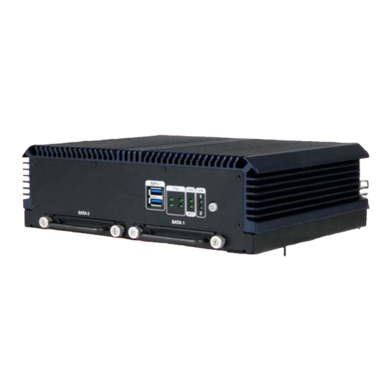
IVS-300 Embedded System 1.1 Overview Figure 1-1: IVS-300 Series Embedded System ® The IVS-300 fanless embedded system is powered by Intel Core™ i5-6300U processor ® ® or Intel Celeron processor J1900. It is designed for vehicle surveillance applications that require minimum installation space. The IVS-300 accepts a wide range of DC power input (9 V–30 V), allowing it to be powered anywhere. -
Page 17: Features
Optional 802.11b/g/n 1T1R wireless connection 1.4 Model Variations There are two models in the IVS-300 embedded system series. The model variations are listed in Table 1-1 below. Processor Memory IVS-300-ULT3-i5/4G ® Intel Core ™ i5-6300U (dual-core, 4 GB DDR4 preinstalled 2.4 GHz, 15W TDP) (max. -
Page 18: Front Panel
IVS-300 Embedded System 1.5 Front Panel An overview of the front panel is shown in Figure 1-2 below. Figure 1-2: Front Panel 1.5.1 LED Indicators The LED indicators on the front panel show the status of power, HDD, Wi-Fi, PoE and GPRS/HSUPA connection. -
Page 19: Rear Panel
IVS-300 Embedded System At regular intervals: low voltage warning (configured by BIOS option: Section 4.3.4) Blinking At irregular intervals (long-short-short): GPS antenna is not connected. The WWAN module is not installed or the SIM slot is not being used. SIM LED Green The WWAN module is installed and the SIM slot is being used for WWAN connection. -
Page 20: Bottom Panel
IVS-300 Embedded System 1.7 Bottom Panel The bottom surface of the IVS-300 contains six retention screw holes for installing two side mounting brackets. Figure 1-5: Bottom Panel 1.8 Dimensions The dimensions of the IVS-300 are listed below and shown in Figure 1-6. Figure 1-6: Dimensions (mm) Page 6... -
Page 21: Technical Specifications
IVS-300 Embedded System 1.9 Technical Specifications The specifications for the Intel based embedded systems are listed below. IVS-300 ® CPU (SoC) ULT3 SKU: Intel Core™ i5-6300U (dual-core, 2.4 GHz, 15W TDP) ® ® BT SKU: Intel Celeron J1900 (quad-core, 2.0 GHz, 10W TDP) System Memory ULT3 SKU: 2 x 260-pin DDR4 SO-DIMM slot (system max. -
Page 22: Table 1-3: Technical Specifications
IVS-300 Embedded System Audio 1 x Audio line-out 1 x Audio mic-in Storage 2 x 2.5” SATA 6Gb/s HDD/SSD removable drive bay (ULT3 model supports RAID function) Chassis Construction Extruded aluminum alloy Power Input 9 V–30 V (±0.3 V) DC One 6-pin power input connector Power Consumption 12V@13.5A (with Intel®... -
Page 23: Unpacking
IVS-300 Embedded System Chapter Unpacking Page 9... -
Page 24: Unpacking
IVS-300 Embedded System 2.1 Unpacking To unpack the embedded system, follow the steps below: Step 1: Use box cutters, a knife or a sharp pair of scissors that seals the top side of the external (second) box. Step 2: Open the external (second) box. Step 3: Use box cutters, a knife or a sharp pair of scissors that seals the top side of the internal (first) box. -
Page 25: Optional Items
IVS-300 Embedded System ACC power cable GPS/GSM antenna Screws (M3*5) for SSD installation Screws (M3*6) for mounting brackets Mounting brackets Driver and manual CD Table 2-1: Package List 2.3 Optional Items The following are optional component(s) which may be separately purchased: Power adapter with transfer cable (P/N: IVIPOWER-6PIN-R10) Page 11... -
Page 26: Table 2-2: Optional Items
IVS-300 Embedded System Wi-Fi kit with AW-CB161H 802.11a/b/g/n/ac and Bluetooth 4.0 combo module (P/N: IVS-WIFI-KIT02-R10) WWAN kit (P/N: IVS-3G-KIT02-R10) OBD-II cable (P/N: 32025-003400-100-RS) OS Image with Windows® Embedded Standard 7 64-bit for IVS-300-BT, DVD-ROM, RoHS (P/N: IVS-300-BT-WES7E64-R10) OS Image with Windows® Embedded Standard 7 64-bit for IVS-300-ULT3, DVD-ROM, RoHS (P/N: IVS-300-ULT3-WES7E64-R10) Table 2-2: Optional Items... -
Page 27: Installation
IVS-300 Embedded System Chapter Installation Page 13... -
Page 28: Anti-Static Precautions
IVS-300 Embedded System 3.1 Anti-static Precautions WARNING: Failure to take ESD precautions during the maintenance of the IVS-300 may result in permanent damage to the IVS-300 and severe injury to the user. Electrostatic discharge (ESD) can cause serious damage to electronic components, including the WAFER series motherboard and the power module. -
Page 29: High Surface Temperature
IVS-300 Embedded System be carried out by qualified personnel who are familiar with the associated dangers. Air Circulation: Make sure there is sufficient air circulation when installing the IVS-300. The IVS-300’s cooling vents must not be obstructed by any objects. Blocking the vents can cause overheating of the IVS-300. -
Page 30: Disassemble The System
IVS-300 Embedded System Step 2: Install WLAN/WWAN module and SIM card (optional) Step 3: Install SATA SSD Step 4: Mount the IVS-300 Step 5: Connect the peripheral devices Step 6: Power the system up Step 0: 3.4 Disassemble the system WARNING: 1. -
Page 31: Figure 3-1: Bottom Panel Retention Screws
IVS-300 Embedded System Figure 3-1: Bottom Panel Retention Screws Step 3: Remove the four internal retention screws (Figure 3-2). Figure 3-2: Internal Chassis Retention Screws Step 4: Remove the front panel retention screws to detach the front panel from the chassis (Figure 3-3). -
Page 32: Pcie Mini Card Installation
IVS-300 Embedded System Step 5: Remove the rear panel retention screws (Figure 3-4). Figure 3-4: Rear Panel Retention Screws Step 6: Lift the entire internal platform out of the heatsink enclosure carefully (Figure 3-5). Step 7: Turn the internal platform over to access the front side of the main board. Figure 3-5: Internal Platform Removal 3.5 PCIe Mini Card Installation The PCIe Mini slot allows installation of either a full-size or half-size PCIe Mini card. -
Page 33: Figure 3-6: Pcie Mini Slot Location
IVS-300 Embedded System Figure 3-6: PCIe Mini Slot Location Step 3: Remove the two retention screws as shown in Figure 3-7. Figure 3-7: Removing the Retention Screws Step 4: Line up the notch on the card with the notch on the slot. Slide the PCIe Mini card into the socket at an angle of about 20º... -
Page 34: Pcie Mini Slot (Mini-Pcie3) Pinouts
IVS-300 Embedded System Figure 3-8: Inserting the Full-size PCIe Mini Card into the Slot at an Angle Step 5: Secure the full-size PCIe Mini card with the retention screws previously removed (Figure 3-9). Figure 3-9: Securing the Full-size PCIe Mini Card 3.5.1 PCIe Mini Slot (MINI-PCIE3) Pinouts The pinouts for the PCIe Mini slot (MINI-PCIE3) are listed in the table below. -
Page 35: Wlan/Wwan Module Installation
IVS-300 Embedded System SIM_VCC SIM_CIO CLK_PCIE_CLK_N SIM_CLK CLK_PCIE_CLK_P SIM_RST PCIRST# PCIE_RXN VCC3 PCIE_RXP VCC1.5 SMB_CLK PCIE_TXN SMB_DATA PCIE_TXP USB_DATA_N USB_DATA_P VCC3 VCC3 DUAL3G LED VCC1.5 VCC3 Table 3-1: PCIe Mini Slot (MINI-PCIE3) Pinouts 3.6 WLAN/WWAN Module Installation To install the optional WLAN or WWAN module, please follow the steps below. Step 1: Access the front side of the main board. -
Page 36: Figure 3-10: Knockouts For External Antennas
IVS-300 Embedded System Figure 3-10: Knockouts for External Antennas Step 3: Locate the half-size PCIe Mini slot for WLAN modules and the full-size PCIe Mini slot for WWAN modules (Figure 3-11). Step 4: Remove the retention screw(s) for PCIe Mini card installation (Figure 3-11). Figure 3-11: WLAN and WWAN Card Slot Locations Step 5: Line up the notch on the WLAN/WWAN module with the notch on the slot. -
Page 37: Figure 3-12: Connecting Rf Cable
IVS-300 Embedded System Figure 3-12: Connecting RF Cable Step 8: Remove the nut and washer from the SMA connector at the other end of the RF cable. Step 9: Insert the SMA connector to the antenna connector hole on the rear panel. Step 10: Secure the SMA connector by inserting the washer and tightening it with nut. -
Page 38: Wwan Module Slot (Mini-Pcie1) Pinouts
IVS-300 Embedded System 3.6.1 WWAN Module Slot (MINI-PCIE1) Pinouts The pinouts for the WWAN module slot (MINI-PCIE1) are listed in the table below. PIN NO. DESCRIPTION PIN NO. DESCRIPTION VCC3 VCC1.5 SIM_VCC SIM_CIO SIM_CLK SIM_RST HSUPA_ON VCC3 VCC1.5 USB_DATA_N USB_DATA_P VCC3 VCC3 3GLED_EN... -
Page 39: Wlan Module Slot (Mini-Pcie2) Pinouts
IVS-300 Embedded System 3.6.2 WLAN Module Slot (MINI-PCIE2) Pinouts The pinouts for the WLAN module slot (MINI-PCIE2) are listed in the table below. PIN NO. DESCRIPTION PIN NO. DESCRIPTION WAKE# VCC3 VCC1.5 CLK_PCIE_CLK_N CLK_PCIE_CLK_P PCIRST# PCIE_RXN VCC3 PCIE_RXP VCC1.5 SMB_CLK PCIE_TXN SMB_DATA PCIE_TXP... -
Page 40: Sim Card Installation
IVS-300 Embedded System 3.7 SIM Card Installation To be able to use the WWAN network connection, SIM cards must be installed in the IVS-300. Follow the steps below to install SIM cards. Step 1: Install a WWAN module into the IVS-300. See Section 3.4. Step 2: Locate the SIM card slots on the rear panel (Figure 3-14). -
Page 41: Figure 3-15: Ssd Bracket Retention Screws
IVS-300 Embedded System Figure 3-15: SSD Bracket Retention Screws Step 2: Pull the bracket out to remove the bracket from the IVS-300 (Figure 3-16). Figure 3-16: Removing SSD Bracket Step 3: Place an SSD onto the bracket and secure the SSD with the bracket by inserting four retention screws (M3*4) into the bottom of the SSD (Figure 3-17). -
Page 42: Figure 3-17: Ssd Retention Screws
IVS-300 Embedded System Figure 3-17: SSD Retention Screws Step 4: Carefully insert the SSD bracket into the slot on the front panel. Make sure the SATA connector on the SSD is securely connected to the SATA connector inside the chassis. Figure 3-18: SSD Installation Step 5: Tighten the two captive screws to secure the SSD bracket. -
Page 43: Mounting The System
IVS-300 Embedded System 3.9 Mounting the System To mount the embedded system onto a wall or some other surface using the two mounting brackets, please follow the steps below. Step 1: Turn the embedded system over. Step 2: Align the three retention screw holes in each bracket with the retention screw holes on the sides of the bottom surface. -
Page 44: External I/O Connectors
IVS-300 Embedded System 3.10 External I/O Connectors This section provides an overview of the external I/O connectors of the IVS-300. 3.10.1 COM Port Connection The IVS-300 has two DB-9 connectors for RS-232 serial port connection. The pinouts for the RS-232 connectors (COM1and COM2) are listed in the figure and table below. Figure 3-20: RS-232 Connector (COM1, COM2) PIN NO. -
Page 45: Dio And Rs-422/485 (Com6) Connection
IVS-300 Embedded System 3.10.2 DIO and RS-422/485 (COM6) Connection The IVS-300 has one DB-15 connector for DIO and RS-422/485 (COM6) connection. The pinouts for the DIO and RS-422/485 connector are listed in the figure and table below. Figure 3-21: DIO and RS-422/485 Connector PIN NO. -
Page 46: Obd-Ii/J1939 Connection
IVS-300 Embedded System 3.10.3 OBD-II/J1939 Connection The IVS-300 has one DB-9 connector for OBD-II/J1939 connection. The pinouts for the OBD-II/J1939 connector are listed in the figure and table below. Figure 3-22: OBD-II/J1939 Connector PIN NO. DESCRIPTION OBD-CAN_H ISO-9141-2-K OBD-CAN_L J1850- J1850+ ISO-9141-2-L Table 3-6: OBD-II/J1939 Connector Pinouts... -
Page 47: Figure 3-23: Obd-Ii Cable
IVS-300 Embedded System User can purchase the optional OBD-II cable (Figure 3-23) to connect the IVS-300 with the vehicle. OBD-II Cable Figure 3-23: OBD-II Cable The pinout locations of OBD-II cable connector are shown below. Figure 3-24: OBD-II Connector Pinouts Page 33... -
Page 48: Gps Speed Pulse/Direction Connection
IVS-300 Embedded System 3.10.4 GPS Speed Pulse/Direction Connection The IVS-300 has a 2-pin connector for GPS speed pulse/direction connection. The pinouts for the GPS speed pulse/direction connector are listed in the figure and table below. Figure 3-25: GPS Speed Pulse/Direction Connector PIN NO. -
Page 49: Power Input Connection
IVS-300 Embedded System 3.11.2 Power Input Connection The IVS-300 has a 9 V–30 V power input connector. The 6-pin power connector pinouts are listed in the figure and table below. Figure 3-26: Power Input Connector PIN NO. DESCRIPTION Table 3-8: Power Input Connector Pinouts To use ACC power, connect the IVS-300 to the vehicle through the ACC power cable. -
Page 50: Power-On Procedure
IVS-300 Embedded System 3.11.3 Power-on Procedure To power-on the IVS-300 please follow the steps below: Step 1: Connect the power source to the power connector to provide power to the system. Step 2: Push the power button until the power LED lights on in green (Figure 3-28). Step 0: Figure 3-28: Power Button 3.12 Driver Installation... -
Page 51: Mobile Ap
IVS-300 Embedded System Audio WLAN (including Bluetooth driver, WWAN module driver, WLAN module driver and IEI Mobile AP application tool) Others: USB 3.0 I/O driver (for ULT3 model only) The following drivers can be installed on the Windows 8 operating system: ... -
Page 52: Usage
IVS-300 Embedded System installation of the WWAN module driver, and IEI Mobile AP application tool. It is recommended to follow the step-by-step procedure to install all of these three drivers/applications. NOTE: After installing the drivers and applications, the IVS-300 must be restarted in order to complete the installation. -
Page 53: Raid Configuration (Ult3 Model Only)
IVS-300 Embedded System Automatically Switch SIM Card: check to allow the system to ping URL1 and URL2 every 30 seconds. If the system is unable to ping both URLs in three minutes, the system will automatically switch to the other SIM card. ... -
Page 54: Figure 3-30: Raid Configuration-Bios Setting
IVS-300 Embedded System Step 1: Connect SATA drives to the system. Connect two or more SATA drives to the system. Make sure the drives have the same capacity, are the same type and have the same speed. NOTE: Make sure the SATA drives are EXACTLY the same when they are configured in a RAID configuration. - Page 55 IVS-300 Embedded System Step 5: Press Ctrl+I. during the system boot process, press Ctrl+I when prompted to enter the RAID configuration software. Intel(R) Rapid Storage Technology – Option ROM – 15.2.0.2740 Copyright (C) Intel Corporation. All rights reserved. RAID Volumes: None defined.
- Page 56 IVS-300 Embedded System Step 7: Create RAID Volume. Highlight Create Volume and press Enter, then choose Y when the warning prompt appears to create volume. Intel(R) Rapid Storage Technology – Option ROM – 15.2.0.2748 Copyright (C) Intel Corporation. All rights reserved. =========================[CREATE VOLUME MENU]======================== Name:...
-
Page 57: Bios
IVS-300 Embedded System Chapter BIOS Page 43... -
Page 58: Introduction
IVS-300 Embedded System 4.1 Introduction The BIOS is programmed onto the BIOS chip. The BIOS setup program allows changes to certain system settings. This chapter outlines the options that can be changed. NOTE: Some of the BIOS options may vary throughout the life cycle of the product and are subject to change without prior notice. -
Page 59: Getting Help
IVS-300 Embedded System Function Decrease the numeric value or make changes Page up Move to the next page Page down Move to the previous page Main Menu – Quit and do not save changes into CMOS Status Page Setup Menu and Option Page Setup Menu -- Exit current page and return to Main Menu F1 key General help, only for Status Page Setup Menu and Option... -
Page 60: Main
IVS-300 Embedded System 4.2 Main The Main BIOS menu (BIOS Menu 1) appears when the BIOS Setup program is entered. The Main menu gives an overview of the basic system information. Aptio Setup Utility – Copyright (C) 2016 American Megatrends, Inc. Main Advanced Chipset... -
Page 61: Advanced
IVS-300 Embedded System 4.3 Advanced Use the Advanced menu (BIOS Menu 2) to configure the CPU and peripheral devices through the following sub-menus: WARNING! Setting the wrong values in the sections below may cause the system to malfunction. Make sure that the settings made are compatible with the hardware. -
Page 62: Acpi Settings
IVS-300 Embedded System 4.3.1 ACPI Settings The ACPI Settings menu (BIOS Menu 3) configures the Advanced Configuration and Power Interface (ACPI) options. Aptio Setup Utility – Copyright (C) 2016 American Megatrends, Inc. Advanced ACPI Settings Select the highest ACPI ACPI Sleep State [Suspend Disabled] sleep state the system will enter when the SUSPEND... -
Page 63: Super Io Configuration
IVS-300 Embedded System 4.3.2 Super IO Configuration Use the Super IO Configuration menu (BIOS Menu 4) to set or change the configurations for the serial ports. Aptio Setup Utility – Copyright (C) 2016 American Megatrends, Inc. Advanced Super IO Configuration Set Parameters of Serial Port 1 (COMA) Super IO Chip... -
Page 64: Serial Port [Enabled]
IVS-300 Embedded System 4.3.2.1.1 Serial Port 1 Configuration Serial Port [Enabled] Use the Serial Port option to enable or disable the serial port. Disabled Disable the serial port Enable the serial port Enabled EFAULT Change Settings [Auto] Use the Change Settings option to change the serial port IO port address and interrupt address. - Page 65 IVS-300 Embedded System IO=2E8h; Serial Port I/O port address is 2E8h and the interrupt IRQ=3, address is IRQ3, 4, 5, 6, 7, 9, 10, 11, 12 5, 6, 7, 9, 10, 11, 12 4.3.2.1.2 Serial Port 2 Configuration Serial Port [Enabled] Use the Serial Port option to enable or disable the serial port.
- Page 66 IVS-300 Embedded System IO=3E8h; Serial Port I/O port address is 3E8h and the interrupt IRQ=3, address is IRQ3, 4, 5, 6, 7, 9, 10, 11, 12 5, 6, 7, 9, 10, 11, 12 IO=2E8h; Serial Port I/O port address is 2E8h and the interrupt IRQ=3, address is IRQ3, 4, 5, 6, 7, 9, 10, 11, 12 5, 6, 7, 9,...
- Page 67 IVS-300 Embedded System IO=2F8h; Serial Port I/O port address is 2F8h and the interrupt IRQ=3, address is IRQ3, 4, 5, 6, 7, 9, 10, 11, 12 5, 6, 7, 9, 10, 11, 12 IO=3E8h; Serial Port I/O port address is 3E8h and the interrupt IRQ=3, address is IRQ3, 4, 5, 6, 7, 9, 10, 11, 12 5, 6, 7, 9,...
-
Page 68: Hardware Monitor
IVS-300 Embedded System 4.3.3 Hardware Monitor The Hardware Monitor menu (BIOS Menu 6) displays operating temperature and fan speeds. Aptio Setup Utility – Copyright (C) 2016 American Megatrends, Inc. Advanced PC Health Status Enable or Disable Smart Smart Fan Function [Enabled] >... -
Page 69: Smart Fan Mode Configuration
IVS-300 Embedded System Fan Speed: Fan1 speed Fan2 speed Voltages: +SOC_VCC +V5S +12S +1.5S VCC3V VSB3V VSB5V 4.3.3.1 Smart Fan Mode Configuration Use the Smart Fan Mode Configuration submenu (BIOS Menu 7) to configure fan temperature and speed settings. Aptio Setup Utility –... -
Page 70: Sys_Fan1 Smart Fan Control [[Auto Duty-Cycle Mode]
IVS-300 Embedded System CPU_FAN1 Smart Fan Control [Auto Duty-Cycle Mode] Use the CPU_FAN1 Smart Fan Control BIOS option to configure the CPU Smart Fan. The fan spins at the speed set in the Manual Manual Duty Mode Duty Mode option ... -
Page 71: Power Management
IVS-300 Embedded System 4.3.4 Power Management Use the Power Management menu (BIOS Menu 8) to configure the power management function. Aptio Setup Utility – Copyright (C) 2016 American Megatrends, Inc. Advanced Current Voltage : +12.2 V Set Low Voltage Warning Low Voltage Warning [9V] (8V~37V) -
Page 72: Power State
IVS-300 Embedded System 1 hour Auto Power Off Delay [20 sec] Use the Auto Power Off Delay option to set the automatic power-off delay time. Configuration options are listed below. 20 sec EFAULT 1 min 5 min ... -
Page 73: Cpu Configuration
IVS-300 Embedded System 4.3.5 CPU Configuration Use the CPU Configuration menu (BIOS Menu 9) to view detailed CPU specifications and configure the CPU. Aptio Setup Utility – Copyright (C) 2016 American Megatrends, Inc. Advanced CPU Configuration When enabled, a VMM can utilize the additional Intel(R) Celeron(R) CPU J1900 @ 1.99GHz hardware capabilities... -
Page 74: Eist [Enabled]
IVS-300 Embedded System L3 Cache: Lists the amount of storage space on the L3 cache. L4 Cache: Lists the amount of storage space on the L4 cache. 64-bit: Indicates if 64-bit system is supported by the CPU. ... -
Page 75: Ide Configuration
IVS-300 Embedded System 4.3.6 IDE Configuration Use the IDE Configuration menu (BIOS Menu 10) to change and/or set the configuration of the SATA devices installed in the system. Aptio Setup Utility – Copyright (C) 2016 American Megatrends, Inc. Advanced IDE Configuration Enable / Disable Serial ATA Serial-ATA (SATA) [Enabled]... -
Page 76: Usb Configuration
IVS-300 Embedded System 4.3.7 USB Configuration Use the USB Configuration menu (BIOS Menu 11) to read USB configuration information and configure the USB settings. Aptio Setup Utility – Copyright (C) 2016 American Megatrends, Inc. Advanced USB Configuration Enables Legacy USB support. -
Page 77: Chipset
IVS-300 Embedded System Enabled Legacy USB support enabled EFAULT Legacy USB support disabled Disabled Auto Legacy USB support disabled if no USB devices are connected 4.4 Chipset Use the Chipset menu (BIOS Menu 12) to access the North Bridge and South Bridge configuration menus. -
Page 78: North Bridge Configuration
IVS-300 Embedded System 4.4.1 North Bridge Configuration Use the North Bridge menu (BIOS Menu 13) to configure the north bridge chipset. Aptio Setup Utility – Copyright (C) 2016 American Megatrends, Inc. Chipset > Intel IGD Configuration Config Intel IGD Settings. Memory Information --------------------- : Select Screen... -
Page 79: Intel Igd Configuration
IVS-300 Embedded System 4.4.1.1 Intel IGD Configuration Use the Intel IGD Configuration submenu (BIOS Menu 14) to configure the graphics settings. Aptio Setup Utility – Copyright (C) 2016 American Megatrends, Inc. Chipset Intel IGD Configuration Select DVMT 5.0 Pre-Allocated (Fixed) DVMT Pre-Allocated [256M] Graphics Memory size... -
Page 80: South Bridge Configuration
IVS-300 Embedded System DVMT Total Gfx Mem [Max] Use the DVMT Total Gfx Mem option to specify the maximum amount of memory that can be allocated as graphics memory. Configuration options are listed below. 128MB 256MB Default 4.4.2 South Bridge Configuration Use the South Bridge menu (BIOS Menu 15) to configure the audio device connected to... -
Page 81: Security
IVS-300 Embedded System Enabled onboard High Definition Audio controller EFAULT automatically detected and enabled XHCI Mode [Smart Auto] Use the XHCI Mode BIOS option to configure the USB xHCI (USB 3.0) controller. Enable the xHCI controller. USB 3.0 ports behave as Enabled USB 3.0 ports. -
Page 82: Boot
IVS-300 Embedded System User Password Use the User Password to set or change a user password. 4.6 Boot Use the Boot menu (BIOS Menu 17) to configure system boot options. Aptio Setup Utility – Copyright (C) 2016 American Megatrends, Inc. Main Advanced Chipset... -
Page 83: Quiet Boot [Enabled]
IVS-300 Embedded System Does not enable the keyboard Number Lock automatically. To use the 10-keys on the keyboard, press the Number Lock key located on the upper left-hand corner of the 10-key pad. The Number Lock LED on the keyboard lights up when the Number Lock is engaged. -
Page 84: Save & Exit
IVS-300 Embedded System 4.7 Save & Exit Use the Save & Exit menu (BIOS Menu 18) to load default BIOS values, optimal failsafe values and to save configuration changes. Aptio Setup Utility – Copyright (C) 2016 American Megatrends, Inc. Main Advanced Chipset Security... - Page 85 IVS-300 Embedded System Restore User Defaults Use the Restore User Defaults option to restore the user defaults to all the setup options. Page 71...
-
Page 86: Troubleshooting And Maintenance
IVS-300 Embedded System Chapter Troubleshooting and Maintenance Page 72... -
Page 87: System Maintenance Overview
IVS-300 Embedded System WARNING: Take Anti-Static precautions whenever maintenance is being carried out on the system components. Failure to take anti-static precautions can cause permanent system damage. For more details on anti-static precautions, please refer to Section 3.1. 5.1 IVS-300 System Maintenance Overview NOTE: When doing maintenance operations on the system, please follow the instructions in this chapter. -
Page 88: The System Doesn't Boot Up
IVS-300 Embedded System Step 2: Check that the power cable connector is properly plugged into the power source. Step 3: Make sure the power button is turned on. Step 4: Plug the system into a monitor and check to see if anything appears on the screen. -
Page 89: Component Replacement Procedure
IVS-300 Embedded System 5.3 Component Replacement Procedure WARNING! Users are not advised to attempt to repair or replace any internal or external components of the IVS-300 embedded system other than those listed below. If any other components fail or need replacement, contact the IEI reseller or vendor you purchased the IVS-300 from or contact an IEI sales representative directly. -
Page 90: Figure 5-1: So-Dimm Locations
IVS-300 Embedded System Figure 5-1: SO-DIMM Locations Step 3: Remove the SO-DIMM by releasing the arms on the SO-DIMM socket. Step 4: Align the new SO-DIMM with the socket. The SO-DIMM must be oriented in such a way that the notch in the middle of the SO-DIMM must be aligned with the plastic bridge in the socket (Figure 5-2). -
Page 91: A Regulatory Compliance
IVS-300 Embedded System Appendix Regulatory Compliance Page 77... - Page 92 IVS-300 Embedded System DECLARATION OF CONFORMITY This equipment is in conformity with the following EU directives: EMC Directive (2004/108/EC, 2014/30/EU) Low-Voltage Directive (2006/95/EC, 2014/35/EU) RoHS II Directive (2011/65/EU, 2015/863/EU) If the user modifies and/or install other devices in the equipment, the CE conformity declaration may no longer apply.
- Page 93 IVS-300 Embedded System Español [Spanish] IEI Integration Corp declara que el equipo cumple con los requisitos esenciales y cualesquiera otras disposiciones aplicables o exigibles de la Directiva 2014/53/EU. Ελληνική [Greek] IEI Integration Corp ΔΗΛΩΝΕΙ ΟΤΙ ΕΞΟΠΛΙΣΜΟΣ ΣΥΜΜΟΡΦΩΝΕΤΑΙ ΠΡΟΣ ΤΙΣ ΟΥΣΙΩΔΕΙΣ ΑΠΑΙΤΗΣΕΙΣ ΚΑΙ ΤΙΣ ΛΟΙΠΕΣ ΣΧΕΤΙΚΕΣ ΔΙΑΤΑΞΕΙΣ ΤΗΣ ΟΔΗΓΙΑΣ 2014/53/EU.
- Page 94 IVS-300 Embedded System Româna [Romanian] IEI Integration Corp declară că acest echipament este in conformitate cu cerinţele esenţiale şi cu celelalte prevederi relevante ale Directivei 2014/53/EU. Slovensko [Slovenian] IEI Integration Corp izjavlja, da je ta opreme v skladu z bistvenimi zahtevami in ostalimi relevantnimi določili direktive 2014/53/EU.
- Page 95 IVS-300 Embedded System FCC WARNING This equipment complies with Part 15 of the FCC Rules. Operation is subject to the following two conditions: This device may not cause harmful interference, and This device must accept any interference received, including interference that may cause undesired operation.
-
Page 96: B Safety Precautions
IVS-300 Embedded System Appendix Safety Precautions Page 82... -
Page 97: Safety Precautions
IVS-300 Embedded System WARNING: The precautions outlined in this chapter should be strictly followed. Failure to follow these precautions may result in permanent damage to the IVS-300. B.1 Safety Precautions Please follow the safety precautions outlined in the sections that follow: B.1.1 General Safety Precautions Please ensure the following safety precautions are adhered to at all times. -
Page 98: Anti-Static Precautions
IVS-300 Embedded System If considerable amounts of dust, water, or fluids enter the device, turn off the power supply immediately, unplug the power cord, and contact the IVS-300 vendor. DO NOT: Drop the device against a hard surface. In a site where the ambient temperature exceeds the rated temperature B.1.2 Anti-static Precautions WARNING:... -
Page 99: Product Disposal
IVS-300 Embedded System B.1.3 Product Disposal CAUTION: Risk of explosion if battery is replaced by an incorrect type. Only certified engineers should replace the on-board battery. Dispose of used batteries according to instructions and local regulations. Outside the European Union–If you wish to dispose of used electrical and electronic products outside the European Union, please contact your local authority so as to comply with the correct disposal method. -
Page 100: Maintenance And Cleaning Precautions
IVS-300 Embedded System B.2 Maintenance and Cleaning Precautions When maintaining or cleaning the IVS-300, please follow the guidelines below. WARNING: For safety reasons, turn-off the power and unplug the embedded system before cleaning. If you dropped any material or liquid such as water onto the embedded system when cleaning, unplug the power cable immediately and contact your dealer or the nearest service center. - Page 101 IVS-300 Embedded System Water or rubbing alcohol–A cloth moistened with water or rubbing alcohol can be used to clean the device. Using solvents–The use of solvents is not recommended when cleaning the device as they may damage the plastic parts. ...
-
Page 102: Cbios Menu Options
IVS-300 Embedded System Appendix BIOS Menu Options Page 88... -
Page 103: Bios Configuration Options
IVS-300 Embedded System C.1 BIOS Configuration Options Below is a list of BIOS configuration options described in Chapter 4. System Date [xx/xx/xx] ......................46 System Time [xx:xx:xx] ....................... 46 ACPI Sleep State [Suspend Disabled] ................48 Serial Port [Enabled] ......................50 Change Settings [Auto] ....................... - Page 104 IVS-300 Embedded System Save Changes and Reset ....................70 Discard Changes and Reset ....................70 Restore Defaults ........................70 Save as User Defaults ......................70 Restore User Defaults ......................71 Page 90...
-
Page 105: D Watchdog Timer
IVS-300 Embedded System Appendix Watchdog Timer Page 91... - Page 106 IVS-300 Embedded System NOTE: The following discussion applies to DOS environment. IEI support is contacted or the IEI website visited for specific drivers for more sophisticated operating systems, e.g., Windows and Linux. The Watchdog Timer is provided to ensure that standalone systems can always recover from catastrophic conditions that cause the CPU to crash.
- Page 107 IVS-300 Embedded System NOTE: When exiting a program it is necessary to disable the Watchdog Timer, otherwise the system resets. Example program: ; INITIAL TIMER PERIOD COUNTER W_LOOP: AX, 6F02H ;setting the time-out value BL, 30 ;time-out value is 48 seconds ;...
-
Page 108: E Hazardous Materials Disclosure
IVS-300 Embedded System Appendix Hazardous Materials Disclosure Page 94... - Page 109 IVS-300 Embedded System The details provided in this appendix are to ensure that the product is compliant with the Peoples Republic of China (China) RoHS standards. The table below acknowledges the presences of small quantities of certain materials in the product, and is applicable to China RoHS only.
- Page 110 IVS-300 Embedded System 此附件旨在确保本产品符合中国 RoHS 标准。以下表格标示此产品中某有毒物质的含量符 合中国 RoHS 标准规定的限量要求。 本产品上会附有”环境友好使用期限”的标签,此期限是估算这些物质”不会有泄漏或突变”的 年限。本产品可能包含有较短的环境友好使用期限的可替换元件,像是电池或灯管,这些元 件将会单独标示出来。 部件名称 有毒有害物质或元素 铅 汞 镉 六价铬 多溴联苯 多溴二苯 醚 (Pb) (Hg) (Cd) (CR(VI)) (PBB) (PBDE) 壳体 显示 印刷电路板 金属螺帽 电缆组装 风扇组装 电力供应组装 电池 O: 表示该有毒有害物质在该部件所有物质材料中的含量均在 SJ/T 11363-2006 (现由 GB/T 26572-2011 取代) 标准规定的限量要求以下。...
Need help?
Do you have a question about the IVS-300-ULT3-i5/4G and is the answer not in the manual?
Questions and answers