Table of Contents
Advertisement
Advertisement
Table of Contents

Related Manuals for JUMO LOGOSCREEN 500


Summary of Contents for JUMO LOGOSCREEN 500
- Page 1 Paperless recorder B 95.5015 Operating Instructions 04.02/00378469...
- Page 3 Contents Introduction Preface ......................5 Arrangement of the documentation ............6 1.2.1 Structure of these Operating Instructions ............6 Typographical conventions ................. 7 1.3.1 Warning signs ....................7 1.3.2 Note signs ...................... 7 1.3.3 Representation ....................8 Instrument description Display and controls ..................9 Operating principle and graphic elements ..........
- Page 4 Contents Event list ...................... 36 Disk manager ....................38 Instrument info ................... 41 Text input ..................... 43 Code number (password entry) ..............44 Configuration parameters Operating example ..................47 Table of configuration parameters ............48 4.2.1 Parameter setting ..................48 4.2.2 Configuration - Instrument data ..............
- Page 5 Contents Standard accessories ................78 Optional accessories ................. 78 Installation Location and climatic conditions .............. 79 Mounting in position .................. 79 Electrical connection Installation notes ..................81 Technical data ..................... 81 Connection diagram .................. 82 TÜV Report on Data Manipulation Security Index...
- Page 6 Contents...
-
Page 7: Introduction
1 Introduction 1.1 Preface Please read these Operating Instructions before commissioning the instru- ment. Keep the operating instructions in a place which is accessible to all us- ers at all times. Please assist us to improve these operating instructions where necessary. Your suggestions will be most welcome. -
Page 8: Arrangement Of The Documentation
1 Introduction 1.2 Arrangement of the documentation The documentation for this instrument consists of the following parts: Operating These operating instructions are included in the delivery. They are addressed Instructions to the equipment manufacturer (OEM), and to the user with appropriate techni- B 95.5015 cal expertise. -
Page 9: Typographical Conventions
1 Introduction 1.3 Typographical conventions 1.3.1 Warning signs The signs for Danger and Caution are used in this manual under the following conditions: Danger This sign is used when there may be danger to personnel if the instructions are disregarded or not followed accurately! Caution This sign is used when there may be damage to equipment or data if the in- structions are disregarded or not followed accurately! -
Page 10: Representation
1 Introduction 1.3.3 Representation Keys Keys are shown in a frame. Both symbols or text are possible. Where a key has multiple functions, the text shown corresponds to the function which is currently active. Screen text Program Texts displayed in the setup program are shown in italics. manager Menu items Edit ! -
Page 11: Instrument Description
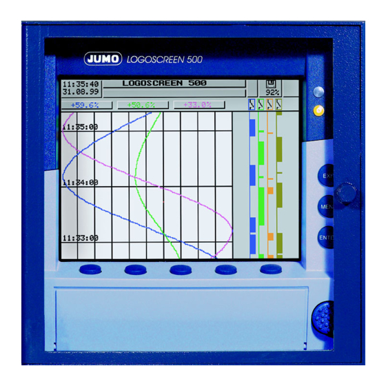
2 Instrument description 2.1 Display and controls Color display 320 x 240 pixel, 27 colors Menu-dependent function keys (softkeys) screen-dependent function, represented by text or symbols Status LED (red) is on continuously while an alarm is present Power LED (green) is on continuously as soon as power is applied;... -
Page 12: Operating Principle And Graphic Elements
2 Instrument description Opening and Status line Header closing the housing door The housing door can be opened or closed by turning the knob 2.2 Operating principle and graphic elements Keys The recorder is operated from eight keys. Three of these have fixed functions, the other five (softkeys) have menu-dependent functions. - Page 13 2 Instrument description Status line The status line is shown in the upper part of the display. It provides information on important actions and states. The status line is always visible, irrespective of the level (operation, parame- ters, configuration). Alarm If an alarm has occured (e.
-
Page 14: Analog Inputs
2 Instrument description Channel line The channel line shows the measurements of the active channels and their unit (channel representation) - measurement - scaling or - bargraph. Alternatively, the header can be switched off altogether. In addition, alarms and out-of-limit conditions are made directly visible, ac- cording to the display mode. -
Page 15: Event Traces
2 Instrument description 2.4 Event traces Signal types In addition to the four logic inputs (extra code), digital signals generated by the instrument itself can also be displayed in the six event traces: Signal Description Logic input 1 — 4 Four logic inputs present in hardware (extra code) Logic channel 1 —... -
Page 16: Counters / Integrators / Timers
2 Instrument description Outputs The digital signals can be used to operate the three relays (extra code). It is possible configure action n.c. (break) n.o. (make) (Configuration ➔ Outputs). External texts So-called “external texts” can be arranged through four logic inputs. Either a standard text or one of the 18 definable texts can be used. - Page 17 2 Instrument description Counters Counter inputs - logic inputs - logic channels - alarms - errors - Modbus-Flag (signal via serial interface) Counter 30Hz max. frequency Weighting The count pulses can be evaluated (weighted). A down counter can be imple- mented by entering a negative weighting (e.g.
-
Page 18: Reporting Periods Of Counts
2 Instrument description 2.5.1 Reporting periods of counts After an adjustable time period (reporting period) the counts are stored for all counters/integrators/timers. The counts of the most recently concluded re- porting period can be graphically displayed. The following counter/integrator types are possible: - periodic The time period (between 1 min and 12 hrs) must additionally be selected in the parameter Period. -
Page 19: Behavior On Instrument Reconfiguration
2 Instrument description The time period for the counter/integrator summation will not be freshly start- ed. The previous counter/integrator values will also not be saved. If you wish to save the previous counter/integrator values, you have to execute the function “Update diskette incl. counters” in the Disk manager menu before resetting. -
Page 20: Math / Logic Module
2 Instrument description 2.6 Math / logic module The math and logic module is available as an extra from instrument software 133.03.xx. As is the case with the counters/integrators/timers, the math and logic module, too, are channels that are not available in hardware, but are cal- culated through the instrument software. - Page 21 2 Instrument description The channel number of a math channel indicates which analog input is being used by the math channel. The following variables are used for the formulae: - analog inputs (AE1 — AE6) - counter/integrator channels (ZI1 — ZI6) - logic inputs (BE1 —...
- Page 22 2 Instrument description Logic module There is also a maximum of 6 logic channels. As is the case with all the other digital signals, the calculated digital (boolean) values can be used for different functions: - recording in the event traces, - as an operating signal for display switch-off, - time synchronization, - timer,...
-
Page 23: Operating Modes
2 Instrument description 2.7 Operating modes 3 operating The instrument has 3 operating modes: modes - normal operation - timed operation - event operation The following settings can, among others, be made for each of the three oper- ating modes: - stored value - storage rate Stored value... -
Page 24: Data Storage
2 Instrument description 2.8 Data storage Recording - internal memory: approx. 350,000 measurements capacity (with option: “Memory expansion to 2MB”: approx. 850,000 measurements) - diskette: approx. 650,000 measurements The recording capacity is reduced when many event messages are also stored. Storage rate Different storage rates, ranging from 1sec to 32767sec, can be configured for normal, event and timed operation under “configuration”. -
Page 25: Operation And Visualization
3 Operation and visualization After starting up the paperless recorder by switching on the supply (power ON), the start logo (company logo) appears. During the screen build-up, the recorder is initialized with the data of the last configuration. After the initialization phase, the measurement diagram (visualiza- tion level) is displayed. -
Page 26: Basic Menu
3 Operation and visualization 3.1 Basic menu The basic menu is the central point from which the various levels of the instru- ment branch out. The following levels are available: - Visualization - Parameters - Configuration - Event list - Disk manager - Instrument info h Select the required level h Confirm selection with E... -
Page 27: Visualization
3 Operation and visualization 3.2 Visualization As has already been mentioned in Chapter 2.2 “Operating principle and graph- ic elements”, the softkeys can be found at the bottom of the screen. They change their function according to the menu and are indicated as symbols or in plain language. -
Page 28: Diagram Representation With Digital Display (Small Measurement)
3 Operation and visualization 3.2.1 Diagram representation with digital display (small measurement) Diagram representation can be reached from the basic menu by calling up the “visualization” menu, or by pressing the key. - Current measurements of the analog inputs including unit - Measurement on red background ⇒... -
Page 29: Diagram Representation With Scaling
3 Operation and visualization 3.2.2 Diagram representation with scaling Scaling start of the selected channel Lower limit marker of the selected channel (no display when alarm is off) Current measurement Channel name Upper limit marker (no display when alarm is off) Scaling end of the selected channel The parameter Parameters ➔... -
Page 30: Large Digital Display (Large Measurement)
3 Operation and visualization 3.2.4 Large digital display (large measurement) This display type is limited to the digital display. 3.2.5 Curve representation (header switched off) This display type is limited to the representation of curves. -
Page 31: Evaluating The Stored Measurement Data
3 Operation and visualization 3.2.6 Evaluating the stored measurement data History The softkey function changes during evaluation and, additionally, the current zoom factor and the cursor position (date and time) are displayed. Scroll operation Current zoom Cursor (violet) (magnification) History activated Date and time of measured values at the cursor position Measured value... - Page 32 3 Operation and visualization Zoom If the zoom factor has to be adjusted, or specific times are to be searched for, then it is necessary to switch the softkey functions. h Press softkey The degree of compression of the measurement data on the screen is given as a ratio in steps (1:1, 1:2, 1:5, 1:10, 1:20, 1:50 and 1:100).
- Page 33 3 Operation and visualization Positioning After pressing the key, the following dialog is available for positioning the cur- the cursor sor on a specific time: After the date and time have been entered and the key has been pressed, the cursor is positioned on the selected time. If no measurement data have been stored for the selected time, then the cur- sor is positioned on the next possible time.
-
Page 34: Counters / Integrators / Operating Time
3 Operation and visualization 3.2.7 Counters / integrators / operating time Count display is available from instrument software 133.03.xx (extra code). If available, the screen below, for example, appears after pressing the softkey, which shows the current counts in numerical form. programmable alarm limit exceeded... -
Page 35: Parameter Setting
3 Operation and visualization 3.3 Parameter setting The “Parameter” level is available to set - contrast, - speed indication, - display off, - diagram view and - counter/integrator reset. All parameters are selected using the keys. Contrast The contrast of the screen can be set here. This ensures that the screen is al- ways legible, even under difficult light conditions. - Page 36 3 Operation and visualization Switch-off event = operating signal In this case, screen saving is performed by using one logic input (extra code). The logic input is selected via the “Operating signal” parameter. Screen saving is deactivated when “Off” is selected. Diagram view ➔...
-
Page 37: Configuration
3 Operation and visualization 3.4 Configuration On calling up the configuration level, the password is requested (factory-set: 9200). It also serves to prevent unauthorized alteration of the configuration. v Chapter 3.9 “Code number (password entry)” Window Like for the other levels, the principle of configuration is also based on menu- technology led window technology. -
Page 38: Event List
3 Operation and visualization 3.5 Event list Events Various events can initiate texts which are included in the event list and saved in the internal memory or on diskette. Events may include: - alarms triggered by out-of-limit conditions on individual channels, - external texts triggered through logic inputs, - system messages (e. - Page 39 3 Operation and visualization Supplementary The instrument automatically supplements the texts by “ON” or “OFF”, to en- text able the distinction between appearance and disappearance of the signal. Example: Standard text Supplementary text Entry in event list Logic input 2 Logic input 2 ON Logic input 2 Logic input 2 OFF...
-
Page 40: Disk Manager
3 Operation and visualization 3.6 Disk manager Automatic The data stored in the measurement data memory (FLASH) of the recorder are storage of saved at regular intervals to the diskette in the instrument. The evaluation pro- measurement gram of the PC (v Chapter 6 “PC evaluation program”) reads the data from data the diskette and provides convenient functions for evaluation. - Page 41 3 Operation and visualization Disk manager Measurement data not yet saved are written to diskette Counter/intergrator reporting periods are concluded and written to diskette, together with the measurement data not yet saved. Counter/integrators are reset (to 0) and restarted. All measurement data in the memory are written to diskette. The configuration data are written to diskette The configuration data are read in from diskette Residual capacity of diskette in percent...
- Page 42 3 Operation and visualization Status Status messages of the disk manager are displayed in the corresponding ac- messages tion window. The following status messages are possible: Status message Description DISKETTE UPDATED Directly before removing the diskette from the instrument, it is necessary to call up Update diskette, so that all the measurement data up to the time of removal are contained on the diskette.
-
Page 43: Instrument Info
3 Operation and visualization Status message Description GOLDCAP WAS EMPTY This message appears when a capacitor is built into the recorder for memory buffering and the instrument has remained switched off for such a long time that the capacitor has become discharged. - Page 44 3 Operation and visualization Instrument info - This menu also includes the version number (e.g. 133.01.01), i.e. the version number of the instrument software. It is important because some functions are only available from a certain version number onwards. - If the “Digital-I/O“ is available (Yes), then the recorder also contains an RS232/RS485 interface.
-
Page 45: Text Input
3 Operation and visualization 3.8 Text input Input The configurable texts can be input either through the setup program or di- options rectly on the instrument. This section describes the input on the instrument. The display below is shown when a text (e. g. Configuration ➔ Texts) is select- Character selection ed at the configuration level for editing by using... -
Page 46: Code Number (Password Entry)
3 Operation and visualization 3.9 Code number (password entry) The following functions are protected ex-factory from unauthorized access by a password request: - the Configuration menu - parts of the Disk manager menu - the Parameters ➔ Counter/Int. reset menu The factory default setting is 9200. - Page 47 3 Operation and visualization Password request in the Configuration menu After the password has been entered in the Configuration menu, an additional security query will appear. You will only be able to access the parameters when you have confirmed the query with...
- Page 48 3 Operation and visualization...
-
Page 49: Configuration Parameters
4 Configuration parameters 4.1 Operating example 1.) if applicable, the code number must also be entered here 2.) cancel entry; the old settings are retained 3.) confirm entry... -
Page 50: Table Of Configuration Parameters
4 Configuration parameters 4.2 Table of configuration parameters The table below lists all the instrument parameters. The order in which the pa- rameters are explained corresponds to the order in which they appear on the instrument (in the menu structure). The first column describes the path via the menus and windows to the particu- lar parameter. -
Page 51: Configuration - Instrument Data
4 Configuration parameters Channel indication Parameters Yes, “Yes” means that the se- ➔ Diagram view lected channels are shown ➔ Channel indication in the header ➔ Analog input 1 — 6 Paper perforations Parameters “Yes” means that paper ➔ Diagram view perforations are shown ➔... - Page 52 4 Configuration parameters Synchronization Configuration Off, Using this parameter (func- ➔ Instrument data of time Logic inp1 — 4 tion), the system clocks of ➔ Date and time several recorders can be ➔ Time simultaneously synchro- synchronization nized. When a logic input has been selected and is oper- ated (transition from “Low to ”High”), then the time...
- Page 53 4 Configuration parameters Memory alarm Configuration 1 — 10 — 100% The signal is activated ➔ Instrument data (diskette when the residual capacity ➔ Memory alarm reserve) of the diskette, or of the internal memory, has fallen to this value. The parameter Memory readout can be used to determine whether the...
-
Page 54: Configuration - Analog Inputs
4 Configuration parameters Enable options Configuration Enter enabling code Enter the enabling code ➔ Instrument data Enabling code you have received here. ➔ Enable options ➔ Enabling code 4.2.3 Configuration - Analog inputs Parameter Value/selection Description Sensor Configuration Off, Depending on the select- ➔... - Page 55 4 Configuration parameters Parameter Value/selection Description End temperature Configuration any value Only for sensor types: ➔Analog inputs current, voltage with linear- ➔ Analog input 1—6 ization for resistance ther- ➔ End mometer, thermocouple. temperature Only for signals which are not yet linearized. Scaling start Configuration -99999 to 0 to +99999...
-
Page 56: Configuration - Event Traces
4 Configuration parameters Parameter Value/selection Description Differential Configuration -99999 to 0 to +99999 ➔Analog inputs ➔ Analog input 1—6 ➔ Alarm ➔ Differential (1) = Low limit (2) = High limit (3) = Differential v Chapter 3.5 “Event list” Text low alarm Configuration Standard text, ➔Analog inputs... -
Page 57: Configuration - Counter/Integrator (Option)
4 Configuration parameters v Chapter 3.8 “Text input” Trace designation Configuration 7 characters ➔ Event traces ➔ Event traces 1 — 4 ➔ Trace designation BE 1 —4 Input signal Configuration Off, The event (digital signal) ➔ Event traces Logic inp1 — 4, which is to be recorded is ➔... - Page 58 4 Configuration parameters Input signal Configuration Off, The parameter is only ➔ Counter/Integrator Logic inp1 — 4, programmable when ➔ Count/In. channs. Logic channel 1 — 6, “Counter” or “Operating ➔ Channel 1 — 6 Low alarm 1 — 6, time”...
- Page 59 4 Configuration parameters Channel name Configuration 7 characters The text that has been ➔ Counter/Integrator (line 1) entered appears together ➔ Counter/In. channs. with line 2 and the current ➔ Channel 1 — 6 count on the recorder ➔ Channel name screen (visualization and event list).
- Page 60 4 Configuration parameters Synchronization Configuration any time Please enter the time at ➔ Counter/Integrator time (00:00:00) which the daily, weekly, ➔ Synchronizat. time monthly or yearly counter/ integrator value is to be saved. Period Configuration 1min, 2min, 3min, 4min, Only programmable when ➔...
-
Page 61: Configuration - Measurement Storage
4 Configuration parameters Reset generation Configuration Off, Determine the event which ➔ Counter/Integrator Logic inp1 — 4, will reset all counter and ➔ Reset generation Logic channel 1 — 6, integrator counts (with- Low alarm 1 — 6, out storing). v See “External reset”... -
Page 62: Configuration - Outputs (Option)
4 Configuration parameters Start time Configuration any time Off when ➔ Meas. storage timed operation start time = ➔ Timed operation end time ➔ Start time End time Configuration any time ➔ Meas. storage timed operation ➔ Timed operation ➔ End time v Chapter 2.7 “Operating Stored value Configuration... -
Page 63: Configuration - Operating Functions
4 Configuration parameters Operating signal Configuration Off, The configured signal is ➔ Outputs outputs Logic inp1 — 4, output to the relay. ➔ Relay K2 — K3 Logic channel 1 — 6, ➔ Operating signal Low alarm 1 — 6, Low comb. -
Page 64: Configuration - Interface
4 Configuration parameters 4.2.10 Configuration - Interface Parameter Value/selection Description Interface type Configuration RS232, Selection of the serial inter- ➔ Interface RS485 face (extra code) ➔ Interface type Protocol Configuration MODBUS, ➔ Interface JBUS ➔ Protocol Baud rate Configuration 9600 baud, ➔... - Page 65 4 Configuration parameters Systematic errors, such as those caused by an unsuitable probe mount- ing, for example, can be compensated using fine calibration. Example: A probe covers a temperature range from 200 to 300°C. It has been fitted in a tunnel oven so unfavorably as to always indicate 10°C less than the temperature of the charge.
- Page 66 4 Configuration parameters...
-
Page 67: Setup Program
5 Setup program 5.1 Hardware and software requirements ® A setup program for (from Version 95 or from NT4.0) is available for Windows the easy configuration of the paperless recorder. Hardware - PC-486DX-2-100 requirements - 16 Mbyte RAM - 15 Mbyte available on hard disk - CD-ROM - 3.5"... -
Page 68: Installing The Setup Program
5 Setup program 5.2 Installing the setup program h Start Microsoft Windows ® Running the installation program If Microsoft Windows has already been started, all Windows pro- grams have to be shut down before installing the setup program. h Insert CD h Select Start ➔... -
Page 69: Data Exchange Between Paperless Recorder And Pc
5 Setup program 5.3 Data exchange between paperless recorder and PC The exchange of configuration data between the recorder and a PC (setup program) is carried out via a 3.5" diskette, or data transfer using the setup in- terface. 5.3.1 Data transfer via diskette h Make the settings in the setup program. -
Page 70: Data Transfer Via Setup Interface
5 Setup program 5.3.2 Data transfer via setup interface h Connect the setup cable to the serial interface of the PC (COM1, COM2, ...) ➔ paperless recorder and plug it into the recess on the left side of the recorder housing. Setup plug h In the setup program, select the required serial interface on the PC by using ➔... -
Page 71: Math And Logic Module
5 Setup program 5.4 Math and logic module The math and logic module is available as an extra from instrument software 133.03.xx. The math and logic module are channels that are not available as hardware but are calculated by the instrument software. If a math channel is used (e.g. - Page 72 5 Setup program 4.) Function selection The function is selected here. All other fields can subsequently be edited according to the function. The input fields “Variable a”, “Var iable b” or “Moving average” have to be edited when one of the standard functions (difference, ratio, humidity, moving average) has been set.
- Page 73 5 Setup program On calling up the function, this dialog box will appear: In the left window you can select the desired signal, in the right window the re- quired operator, and enter them into the formula by activating the correspond- button.
-
Page 74: Character Set
5 Setup program 5.5 Character set 0162 ¢ 0210 Ò 0163 £ 0211 Ó " 0164 ¤ 0212 Ô 0165 ¥ 0213 Õ 0166 ¦ 0214 Ö 0167 § 0215 × & 0168 ¨ 0216 Ø ’ 0169 © 0217 Ù... - Page 75 5 Setup program Input of special (Special) characters which cannot be input directly from the keys of the PC are input by using the A key and the number combination shown in the table. characters Example The special character © has to be input: h Position the cursor with the mouse, or by using the cursor keys, on the insertion point of the character h Press the A key and hold it down...
- Page 76 5 Setup program...
-
Page 77: Pc Evaluation Program
6 PC evaluation program 6.1 Program description Das PC evaluation program (PCA) is described in more detail in the Operating Instructions B 95.5099. The PC evaluation program (PCA) can be run from Windows95 and is available for managing, archiving, visualization and evaluation of the recorder data saved on diskette. - Page 78 6 PC evaluation program Features Some features in brief: - The data from differently configured instruments are recognized by the PCA evaluation program and stored in an archive database. The entire manage- ment is performed automatically. Only an identifier (supplementary descrip- tion) has to be manually provided by the user.
-
Page 79: Identifying The Instrument Version
7 Identifying the instrument version 7.1 Type designation Paperless recorder for capturing, visualizing, storing and evaluating measurement data (1) Basic version 955015/14 paperless recorder with 3 analog inputs paperless recorder with 3 analog inputs 955015/24 incl. setup and PCA evaluation program 955015/15 paperless recorder with 6 analog inputs paperless recorder with 6 analog inputs... -
Page 80: Standard Accessories
7 Identifying the instrument version 7.2 Standard accessories - 1 Operating Instructions B 95.5015 - 2 mounting brackets - cable-tie with foot (can be released) for strain relief of the connected sensor leads 7.3 Optional accessories - setup program on CD-ROM, multilingual - PC interface cable with TTL/RS232 converter and adapter - PC evaluation program on CD-ROM, multilingual - PCA communication server on CD-ROM, multilingual... -
Page 81: Location And Climatic Conditions
8 Installation 8.1 Location and climatic conditions The location should as far as possible be free from vibration. Stray electro- magnetic fields, e. g. from motors, transformers etc. should be avoided. The ambient temperature at the location can be between 0 and +45°C, at a relative humidity of ≤... - Page 82 8 Installation h Insert the paperless recorder from the front into the panel cut-out Fitting in position h From the back of the panel, hook the two mounting brackets into the recesses on the sides of the housing. The flat sides of the brackets must be against the housing.
-
Page 83: Installation Notes
9 Electrical connection 9.1 Installation notes The choice of the cable, the installation and the electrical connection must conform to the requirements of VDE 0100 “Regulations on the In- stallation of Power Circuits with nominal voltages below 1000V”, or the appropriate local regulations. -
Page 84: Connection Diagram
9 Electrical connection 9.3 Connection diagram The electrical connection must only be carried out by qualified per- sonnel. Rear view Terminals Connection symbol (for screw-clamp connectors) 3/6 channel paperless recorder Analog inputs Connector Thermocouple 1 to 6 Resistance thermometer 1 to 6 in 2-wire circuit Resistance thermometer 1 to 6... - Page 85 9 Electrical connection Resistance thermometer 1 to 6 in 4-wire circuit Voltage input ≤ 210mV 1 to 6 Voltage input > 210mV 1 to 6 Current input 1 to 6 Supply Supply voltage N (L-) L1 (L+) Interfaces (extra code) RS232C 2 RxD receive data...
- Page 86 9 Electrical connection Setup interface The setup interface can be found on the left side of the housing (seen from the front) Setup plug...
- Page 87 10 TÜV Report on Data Manipulation Security...
- Page 88 10 TÜV Report on Data Manipulation Security...
- Page 89 10 TÜV Report on Data Manipulation Security...
- Page 90 10 TÜV Report on Data Manipulation Security...
- Page 91 11 Index Action (outputs) Active operating mode Alarm Alarm (counter/integrator) Alarm delay Alarm text (counter/integrator) 52–54 Analog inputs 9, 24 Basic menu 41–42 Battery empty Baud rate Calibration status Channel (counter/integrator) 27, 49 Channel indication 12, 48, 53 Channel line Channel name Channel name (counter/integrator) 12, 25, 48...
- Page 92 11 Index 15, 55 Counters Daily end time (counter/integrator) Daily start time (counter/integrator) Data format 41–42 Data lost Data Manipulation Security Date Decimal place Decimal place (counter/integrator) 11, 21 Diagram speed Diagram view Differential 25, 28 Digital display Disk code number Disk manager Disk reserve Display...
- Page 93 11 Index Factory setting Filter constant Fine calibration Function (counter/integrator) Hardware and software requirements 10, 25, 48–49, 53 Header High limit History Humidity measurement Import/export errors 54–55 Input signal Input signal (counter/integrator) Installation notes Instrument address Instrument info Instrument name Instrument software 15, 55 Integrator...
- Page 94 11 Index 13, 51 Memory alarm Memory readout 9, 24 Menu key Mounting in position Normal operation operating signal storage rate store status stored value Note signs Operating function Operating modes Operating principle 48, 59 Operating signal 60–61 Operating signal (outputs) Option enable Code No.
- Page 95 11 Index Returning RS232/RS485 code number Scaling Scaling end Scaling start 9, 48 Screen saver Screen text Scroll operation Sensor Sensor monitoring Setup program, installation of 25–26, 48 Signal type Signal types 9–10 Softkey Speed Speed indication Standard text Start temperature Start time (timed operation) Start value actual...
- Page 96 11 Index Trace designation Transfer 67–68 PC-recorder 67–68 recorder-PC Type (counter/integrator) Type designation Underrange Unit Unit (counter/integrator) Unit of measurement variable Version number Waiting time Warranty Weekday (counter/integrator) 15, 56 Weighting (counter/integrator) Window technology Zoom...
- Page 100 M. K. JUCHHEIM GmbH & Co JUMO Instrument Co. Ltd. JUMO PROCESS CONTROL INC. Street address: JUMO House 885 Fox Chase, Suite 103 Moltkestraße 13 - 31 Temple Bank, Riverway Coatesville, PA 19320, USA 36039 Fulda, Germany Harlow, Essex CM20 2TT, UK...
Need help?
Do you have a question about the LOGOSCREEN 500 and is the answer not in the manual?
Questions and answers