Table of Contents
Advertisement
V1.00.001
2017-09-22
Note: This user manual applies to the following CReader models: CReader 6011,
CReader 7001, CReader 7001F, CReader 8001, CReader 8011, CReader 8021 and
CReader 9081. All illustrations and descriptions herein are only for reference. We
reserve the right to make changes due to software update without prior written
notice.
Advertisement
Table of Contents

Related Manuals for Launch CReader 6011


Summary of Contents for Launch CReader 6011
- Page 1 V1.00.001 2017-09-22 Note: This user manual applies to the following CReader models: CReader 6011, CReader 7001, CReader 7001F, CReader 8001, CReader 8011, CReader 8021 and CReader 9081. All illustrations and descriptions herein are only for reference. We reserve the right to make changes due to software update without prior written...
- Page 2 LAUNCH or its affiliates. In countries where any of the LAUNCH trademarks, service marks, domain names,...
- Page 3 The right is reserved to make change at any time without notice. Neither LAUNCH nor its affiliates shall be liable to the purchaser of this unit or third parties for damages, losses, costs or expenses incurred by purchaser or...
- Page 4 CReader Series English User’s Manual LAUNCH engine is running. Keep the tool dry, clean, free from oil/water or grease. Use a mild detergent on a clean cloth to clean the outside of the tool, when necessary.
-
Page 5: Table Of Contents
4.2 Settings ....................10 5. Diagnose ......................12 5.1 OBDII/EOBD Diagnosing ................. 13 5.2 System Diagnosing (Only for CReader 6011/8001/8011/8021) ....16 5.2.1 Read Vehicle Information ..............17 5.2.2 Read Fault Code ................17 5.2.3 Clear Fault Code ................17 5.2.4 Read Data Stream ................ - Page 6 CReader Series English User’s Manual LAUNCH 5.3.5 Diesel Particulate Filter (DPF) Regeneration (Only applies to CReader 7011F/9081) ................20 5.3.6 Tire Pressure Monitor System Reset (Only applies to CReader 9081) ........................ 20 5.3.7 ABS Bleeding (Only applies to CReader 7011F/9081) ....21 5.3.8 Gear Learning (Only applies to CReader 9081) ......
-
Page 7: Introduction
6011/7001/7001F/8001/8011/8021/9081 supports all 10 modes of OBD II test for a complete diagnosis. CReader 6011 In addition to the full OBDII/EOBD diagnostic functions, CReader 6011 also supports the diagnosis of the electronic control systems of vehicle, such as ABS and SRS. -
Page 8: General Information
CReader Series English User’s Manual LAUNCH cable. The memory card is highly recommended to update your tool. Note: CReader 6011/7001/7001F/8001/8011/8021/9081 may automatically reset while being disturbed by strong static electricity. THIS IS A NORMAL REACTION. 2. General Information 2.1 On-Board Diagnostics (OBD) II... -
Page 9: Location Of The Data Link Connector (Dlc)
CReader Series English User’s Manual LAUNCH Figure 2-1 2.3 Location of the Data Link Connector (DLC) The DLC (Data Link Connector or Diagnostic Link Connector) is typically a 16-pin connector where diagnostic code readers interface with the vehicle’s on-board computer. The DLC is usually located 12 inches from the center of the instrument panel (dash), under or around the driver’s side for most vehicles. -
Page 10: Obd Ii Readiness Monitors
CReader Series English User’s Manual LAUNCH Figure 2-2 2.4 OBD II Readiness Monitors An important part of a vehicle’s OBD II system is the Readiness Monitors, which are indicators used to find out if all of the emissions components have been evaluated by the OBD II system. -
Page 11: Obd Ii Monitor Readiness Status
CReader Series English User’s Manual LAUNCH engine system components require the vehicle to be operated under specific conditions before the monitor is ready. These monitors are termed non-continuous monitors and are listed below: 1) EGR System 2) O Sensors 3) Catalyst... -
Page 12: Obd Ii Definitions
CReader Series English User’s Manual LAUNCH 2.6 OBD II Definitions Powertrain Control Module (PCM) – It is the OBD II terminology for the on-board computer that controls engine and drive train. Malfunction Indicator Light (MIL) -- Malfunction Indicator Light (Service Engine Soon, Check Engine) is a term used for the light on the instrument panel. - Page 13 CReader Series English User’s Manual LAUNCH RPM, vehicle speed, air flow, engine load, fuel pressure, fuel trim value, engine coolant temperature, ignition timing advance, or closed loop status. Fuel Trim (FT) -- Feedback adjustments to the base fuel schedule. Short-term fuel trim refers to dynamic or instantaneous adjustments.
-
Page 14: Product Descriptions
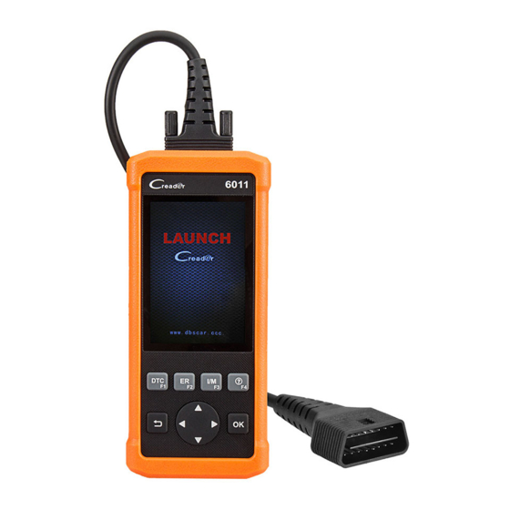
CReader Series English User’s Manual LAUNCH 3. Product Descriptions 3.1 Outline of CReader 6011/7001/7001F/8001/8011/8021/9081 Figure 3-1 CReader 6011/7001/7001F/8001/8011/8021/9081 Front View Note: CReader 6011/7001/7001F/8001/8011/8021/9081 feature same appearance. Name Descriptions To connect the tool to the vehicle's DLC (Data Link DB-15 connector Connector) via the diagnostic cable. -
Page 15: Specifications
Storage temperature: -20 to 70°C (-4 to 158 F°) External Dimension: 195mm(L) x 86mm(W) x 32mm(H) Weight: 460g 3.3 Accessories 1. CReader 6011/7001/7001F/8001/8011/8021/9081 handset 2. Diagnostic cable 3. User’s Manual 4. Memory card (Built-in) 5. Memory card reader... -
Page 16: Connection & Settings
CReader Series English User’s Manual LAUNCH 4. Connection & Settings 4.1 Connection 1. Turn the ignition off. 2. Locate vehicle’s DLC socket: Refer to Fig. 2-2 for the location. In case no DLC is found, please refer to Automobile Repair Manual. - Page 17 CReader Series English User’s Manual LAUNCH Figure 4-2 1) Language This option enables you to set the user interface language. Note: Due to continuous software upgrade, language interface may differ from different software versions. 2) Unit of Measure This option allows you to set measurement unit.
-
Page 18: Diagnose
CReader Series English User’s Manual LAUNCH 5. Diagnose Select [Diagnose] in Main Menu and press [OK], the screen will display Monitor Status interface as following figure 5-1: Figure 5-1 (Only applies to CReader 6011/8001/8011/8021) Figure 5-1 (Only applies to CReader 7001/7001F/9081) -
Page 19: Obdii/Eobd Diagnosing
CReader Series English User’s Manual LAUNCH 5.1 OBDII/EOBD Diagnosing This option presents a quick way to check for DTCs, isolate the cause of the illuminated Malfunction Indicator Lamp (MIL), check monitor status prior to emissions certification testing, verify repairs, and perform a number of other services that are emission-related. - Page 20 CReader Series English User’s Manual LAUNCH Figure 5-3 It mainly includes the following functions: 1. Read Codes This option is used to identify which section of the emission control system has malfunctioned. 2. Erase Codes After reading the retrieved codes from the vehicle and certain repairs have been carried out, you can use this function to erase the codes from the vehicle.
- Page 21 CReader Series English User’s Manual LAUNCH meet federal clean-air standards. I/M Readiness indicates whether or not the various emissions-related systems on the vehicle are operating properly and are ready for Inspection and Maintenance testing. The purpose of the I/M Readiness Monitor Status is to indicate which of the vehicle’s Monitors have run and completed their diagnosis and testing (as...
-
Page 22: System Diagnosing (Only For Creader 6011/8001/8011/8021)
This option displays the vehicle information, such as VIN (Vehicle identification Number), CID (Calibration ID) and CVN (Calibration Verification Number). 5.2 System Diagnosing (Only for CReader 6011/8001/8011/8021) This function is specially designed to diagnose the two electronic control systems [ABS (Anti-lock Brake System) + SRS (Supplemental Restraint System)] of single vehicle model. -
Page 23: Read Vehicle Information
Note: This function is not available on CReader 6011. For CReader 7001/7001F/9081, just follow the flowchart below to perform resetting. - Page 24 CReader Series English User’s Manual LAUNCH Follow the instructions Select “Diagnose” on the screen to operate Select the service mode Select “Reset” (The available mode (e.g. oil lamp reset etc.) varies from vehicle to vehicle) Select the desired reset item (e.g. oil lamp reset Select the car brand etc.)
-
Page 25: Oil Reset Service (Only Applies To Creader 7001/7011F/8001/8011/ 8021/9081)
CReader Series English User’s Manual LAUNCH 5.3.1 Oil Reset Service (Only applies to CReader 7001/7011F/8001/8011/ 8021/9081) This function allows you to perform reset for the engine oil life system, which calculates an optimal oil life change interval depending on the vehicle driving conditions and climate. -
Page 26: Diesel Particulate Filter (Dpf) Regeneration (Only Applies To Creader 7011F/9081)
CReader Series English User’s Manual LAUNCH and battery matching will be done. Battery matching must be performed in the following cases: a) Main battery is replaced. Battery matching must be performed to clear original low battery information and prevent the related control module from detecting false information. -
Page 27: Abs Bleeding (Only Applies To Creader 7011F/9081)
CReader Series English User’s Manual LAUNCH 5.3.7 ABS Bleeding (Only applies to CReader 7011F/9081) This function allows you to perform various bi-directional tests to check the operating conditions of Anti-lock Braking System (ABS). 1. When the ABS contains air, the ABS bleeding function must be performed to bleed the brake system to restore ABS brake sensitivity. -
Page 28: Injector Coding (Only Applies To Creader 9081)
CReader Series English User’s Manual LAUNCH function must be performed so that the immobilizer control system on the car identifies and authorizes remote control keys to normally use the car. When the ignition switch key, ignition switch, combined instrument panel, ECU, BCM, or remote control battery is replaced, anti-theft key matching must be performed. -
Page 29: Help
CReader Series English User’s Manual LAUNCH 6. Help This menu enables you to view tool information and OBD introduction. In main menu, select [Help] and press [OK] to enter figure 6-1. Figure 6-1 6.1 DLC Location Information This option helps you to find the location of the vehicle’s DLC. - Page 30 CReader Series English User’s Manual LAUNCH Figure 6-2 Press [ ]/[ ] button to move the highlight bar to different position. Press [ ]/[ ] button to alter the value, then press [OK] button, the screen will display definition of the DTC.
- Page 31 CReader Series English User’s Manual LAUNCH Figure 6-3 Note: You are strongly recommended to note down the Serial Number and Register Code in figure 6-3 since these 2 pieces of information are required while registering your tool. 6.5 About OBD...
-
Page 32: Register & Update
1. System requirements: Windows XP, 7, 8 or Windows 10. 2. Go to http://mycar.x431.com, click “Products” -> “Creader Online” -> “CReader 6011/7001/8001/8011/8021/9081” to download the update tool and install it on the computer. Figure 7-1 (For CReader 6011) Figure 7-1 (For CReader 7001&CReader 7001F) - Page 33 CReader Series English User’s Manual LAUNCH Figure 7-1 (For CReader 8001) Figure 7-1 (For CReader 8011)
- Page 34 Figure 7-1 (For CReader 9081) There are 2 methods available to update your tool. You may choose one of the following to proceed. Method 1: Via Memory Card (recommended) 1. Launch the update tool, a screen similar to figure 7-2 will appear:...
- Page 35 CReader Series English User’s Manual LAUNCH Figure 7-2 2. In figure 7-2, type in the Product Serial Number (located at the back of the tool). Note: Once the S/N is entered, “Restore System” becomes activated, which is used to restore system if a new memory card is replaced.
- Page 36 CReader Series English User’s Manual LAUNCH 5. After the tool has powered up and entered the main menu screen, move the highlight bar on the “Help” icon and press [OK]. Figure 7-4 6. Highlight the “Tool Information” in figure 7-4 and press [OK].
- Page 37 CReader Series English User’s Manual LAUNCH 7. The Register Code shown in figure 7-5 is the Register Code needed in step 3. (Return to step 3 and input the Register Code and then proceed) 8. Install the memory card from the tool into the supplied memory card adaptor and insert into the USB port of the computer.
- Page 38 CReader Series English User’s Manual LAUNCH Figure 7-7 3. Press [OK] to configure this tool as a USB device. See figure 7-8. Figure 7-8 Note: The Serial Number and Register Code shown in this figure are needed for inputting in Steps 4-6.
- Page 39 CReader Series English User’s Manual LAUNCH 4. Launch the update tool, a screen similar to figure 7-9 will appear. Figure 7-9 5. Type in the Serial Number. Click [Device Upgrade] to input the information and click [Submit] to enter the update page.
-
Page 40: Faq
CReader Series English User’s Manual LAUNCH 8. FAQ Here we list some frequently asked questions and answers relating to the tool. Question: System halts when reading data stream. What is the reason? Answer: It may be caused by a slackened connector. Please turn off the tool, firmly connect the connector, and switch it on again. - Page 41 The exclusive remedy for any automotive meter found to be defective is repair or replacement, and LAUNCH shall not be liable for any consequential or incidental damages.
- Page 42 CReader Series English User’s Manual LAUNCH Statement: LAUNCH reserves the rights to make any change to product designs and specifications without notice. The actual object may differ a little from the descriptions in the manual in physical appearance, color and configuration. We have tried our best to make the descriptions and illustrations in the manual as accurate as possible, and defects are inevitable.
Need help?
Do you have a question about the CReader 6011 and is the answer not in the manual?
Questions and answers
как обновить лаунч 6011
To update the Launch CReader 6011, follow these steps:
1. Select Tool Information: Navigate to [Tool Information] and press [OK].
2. Obtain Register Code: The Register Code will be displayed. Note this code for later use.
3. Reopen CR Update Suite: Open the CR Update Suite and select the updates you want to install or click [Select All], then click [Download].
4. Power the Tool: Connect the device to a computer via USB or to a vehicle via the OBDII port.
5. Start Update: The tool will prompt for an upgrade. Click [OK] to start updating.
6. Wait for Completion: A progress bar will appear. The update may take several minutes if the file is large.
7. Finish: Once the update is complete, the registration and upgrade process is done.
This answer is automatically generated