Table of Contents
Advertisement
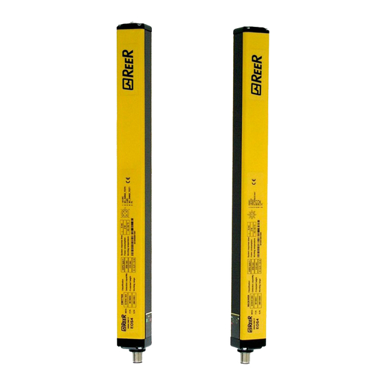
REER SpA
via Carcano 32
10153 – Torino
Italy
dichiara che le barriere fotoelettriche EOS2 sono Dispositivi Elettrosensibili di Sicurezza (ESPE) di :
Tipo 2 (secondo la Norma CEI EN 61496-1:2005; CEI EN 61496-2:2007)
SIL 2 (secondo la Norma CEI EN 61508:2002)
SILCL 2 (secondo la Norma CEI EN 62061:2005 + CEI EN 62061/EC2:2008)
PL d (secondo la Norma UNI EN ISO 13849-1:2008)
declares that the EOS2 photoelectric safety barriers are :
Type 2 (according the Standard IEC 61496-1:2004; IEC 61496-2:2006)
SIL 2 (according the Standard IEC 61508:1998)
SILCL 2 (according the Standard IEC 62061:2005)
PL d (according the Standard ISO 13849-1:2006)
Electro-sensitive Protective Equipments (ESPE)
realizzati in conformità alle seguenti Direttive Europee:
complying with the following European Directives:
2006/42/CE "Direttiva Macchine"
"Machine Directive"
2004/108/CE "Direttiva Compatibilità Elettromagnetica"
2006/95/CE "Direttiva Bassa Tensione"
"Low Voltage Directive"
e sono identiche all'esemplare esaminato ed approvato con esame di tipo CE da:
and are identical to the specimen examined and approved with a CE - type approval by:
TÜV SÜD Rail GmbH – Ridlerstrasse 65 – D-80339 – Muenchen – Germany
Carlo Pautasso
Direttore Tecnico
Technical Director
Dichiarazione CE di conformità
EC declaration of conformity
"Electromagnetic Compatibility Directive"
Torino, 1/1/2010
Giancarlo Scaravelli
Presidente
President
Advertisement
Table of Contents

Related Manuals for Reer EOS2 A


Summary of Contents for Reer EOS2 A
- Page 1 Dichiarazione CE di conformità EC declaration of conformity Torino, 1/1/2010 REER SpA via Carcano 32 10153 – Torino Italy dichiara che le barriere fotoelettriche EOS2 sono Dispositivi Elettrosensibili di Sicurezza (ESPE) di : Tipo 2 (secondo la Norma CEI EN 61496-1:2005; CEI EN 61496-2:2007)
-
Page 2: Table Of Contents
Configuration and operating modes (Master Models / With integrated control functions) ......................19 Automatic operation ..................19 Manual operation..................19 Connection of external contactors K1 and K2 ..........20 Examples of connection with REER safety modules ........21 OPERATION AND TECHNICAL DATA ....................22 Light signals ....................22 Emitter light signals..................22 Receiver light signals ..................22 Internal TEST function..................23... -
Page 3: Nd December 2009 • Rev
EOS2 SAFETY LIGHT CURTAIN ABBREVIATIONS AND SYMBOLS USED IN THIS MANUAL FE = Functional earth (earth connection) M/S = Master/Slave System OSSD = Output Signal Switching Device (Light curtain’s solid state safety outputs) TX = Safety light curtain emitter. RX = Safety light curtain receiver. Hand protection light curtains Arm and leg protection light curtains. -
Page 4: Introduction
IEC 61496-1,2 and EN 61496-1 standards. The EOS2 is available in three different versions: EOS2 A Type 2 light curtain consisting of Emitter plus Receiver with automatic reset. EOS2 X... -
Page 5: Principle Of Operation
EOS2 SAFETY LIGHT CURTAIN PRINCIPLE OF OPERATION If the protected area is clear, the two outputs on the Receiver are active and enable the machine to which they are connected to operate normally. Each time that an object bigger than or equal in size to the resolution of the system intercepts the optical path of one or more beams, the Receiver deactivates its own outputs. -
Page 6: Installation
EOS2 SAFETY LIGHT CURTAIN INSTALLATION Before installing the EOS2 safety system, check all the conditions listed below: The level of protection of EOS2 (Type 2, SIL2, SILCL2, PLd) must be compatible with the level of danger of the system to be protected. The safety system is used only as a stopping device and not to control the machine. -
Page 7: Positioning
EOS2 SAFETY LIGHT CURTAIN Positioning The Emitter EOS2E and the Receiver EOS2R must be positioned so that it is impossible to access the dangerous area from above, from below and from the sides without intercepting one of the beams. Useful indications for correct positioning of the light curtain are provided in the figure below. -
Page 8: Master/Slave Positioning
EOS2 SAFETY LIGHT CURTAIN Master/Slave Positioning In addition to standard models (that can be positioned either horizontally or vertically), EOS2 can be purchased in a MASTER/SLAVE configuration. This configuration comprises two (or three) pairs of light curtains in which the two (or three) Emitters and the two (or three) Receivers are connected in series. -
Page 9: Calculation Of Safety Distance
EOS2 SAFETY LIGHT CURTAIN Calculation of safety distance The light curtain must be positioned at a distance equal to or greater than the minimum safety distance S so that the dangerous point can be reached only after stopping the dangerous movement of the machine (Figure 5). According to the EN999:2008 European standards, the minimum safety distance S must be calculated using the following formula : S = K (t1 + t2) + C... -
Page 10: Multiple Systems
EOS2 SAFETY LIGHT CURTAIN Multiple systems When several EOS2 are used, precautions must be taken to prevent optical interference between these: position the elements so that the beam of the Emitter of one system is received only by its respective Receiver. Figure 6 provides examples of correct positioning of two photo-electric systems. -
Page 11: Use Of Deflecting Mirrors
EOS2 SAFETY LIGHT CURTAIN Use of deflecting mirrors For protection or control of areas accessible from several sides, one or more deflecting mirrors can be used in addition to the Emitter and Receiver. Deflecting mirrors make it possible to redirect the beams generated by the Emitter on several sides. -
Page 12: Distance From Reflective Surfaces
EOS2 SAFETY LIGHT CURTAIN Distance from reflective surfaces The presence of reflective surfaces close to the light curtain may cause occasional reflections that prevent sensing. Referring to Figure 8, object A is not detected due to surface S that, reflecting the beam, closes the optical path between the Emitter and Receiver. -
Page 13: Mechanical Assembly And Optical Alignment
EOS2 SAFETY LIGHT CURTAIN Mechanical assembly and optical alignment The Emitter and Receiver must be installed facing each other, at a distance equal to or less than that indicated in the technical data. Using the provided inserts and fastening brackets, place the Emitter and Receiver so that they are aligned and parallel to each other, and with the connectors facing the same side. -
Page 14: Vertical Positioning Of The Light Curtain
EOS2 SAFETY LIGHT CURTAIN Vertical positioning of the light curtain Models with 30, 40mm resolution point of Light curtain These models are suitable for hand detection. The minimum safety distance S is calculated according to the following formula: S = 2000 (t ) + 8(D-14) direction (D=resolution) -
Page 15: Multibeam Models
EOS2 SAFETY LIGHT CURTAIN point of danger Multibeam Models These models are suitable for whole body Light grid detection and must not be used to detect arms or legs. minimum safety distance determined according to the following formula: direction S = 1600 (t ) + 850 approach The recommend height H from the reference surface G... -
Page 16: Electrical Connections
EOS2 SAFETY LIGHT CURTAIN Electrical connections WARNINGS Before making electrical connections, make sure that the mains voltage matches the one indicated in the technical data. The Emitter and Receiver must be powered at a 24Vdc±20% (PELV, in compliance with the standard EN 60204-1 (Chapter 6.4)). The electrical connections must be made according to the wiring diagrams provided in this manual. -
Page 17: Emitter Connections
EOS2 SAFETY LIGHT CURTAIN Emitter connections STANDARD - WITH INTEGRATED CONTROL FUNCTIONS - MASTER MODELS M12 5-pin primary connectors. PIN COLOUR NAME TYPE DESCRIPTION Brown 24VDC 24VDC power supply Light curtain configuration White RANGE0 complying with the EN61131-2 standard (ref. Table 5) INPUT Blue... -
Page 18: Receiver Connections
EOS2 SAFETY LIGHT CURTAIN Receiver connections STANDARD MODELS - M12, 5-pin connector. PIN COLOUR NAME TYPE DESCRIPTION OPERATION Brown 24VDC 24VDC power supply White OSSD1 Static safety output 1 PNP active high Blue 0VDC 0VDC power supply Black OSSD2 Static safety output 2 PNP active high Grey Ground connection... -
Page 19: Warnings Regarding Connection Cables
EOS2 SAFETY LIGHT CURTAIN SLAVE/SLAVE2 MODELS - M12, 5-pin primary connectors. COLOUR NAME DESCRIPTION Brown 24VDC 24VDC power supply Communication White LINE_A MASTER-SLAVE Blue 0VDC 0VDC power supply Communication Black LINE_B MASTER-SLAVE Grey Ground connection Table 10 - M12, 5 pins Primary Slave RX MASTER MODELS - M12, 5-pin Secondary Connector. -
Page 20: Configuration And Operating Modes (Master Models / With Integrated Control Functions)
EOS2 SAFETY LIGHT CURTAIN Configuration and operating modes (Master Models / With integrated control functions) The operating mode of the EOS2 light curtain is set by making suitable connections on the M12 – 8-pin connector of the Receiver (Table 12). CONNECTIONS OPERATING MODE SEL_A (PIN 5) -
Page 21: Connection Of External Contactors K1 And K2
EOS2 SAFETY LIGHT CURTAIN The Restart command must be installed outside the danger area in a position where the danger area and the entire work area concerned are clearly visible. It must not be possible to reach the control from inside the danger area. Connection of external contactors K1 and K2 In both operating modes, it is possible to activate control of the external contactors K1/K2. -
Page 22: Examples Of Connection With Reer Safety Modules
2 and 4 of the Emitter as indicated in Table 4. Figure 21 - EOS2 A: Manual operation with AD SR1 module For correct operation of the light curtain, connect pins 2 and 4 of the Emitter as indicated in Table 4. -
Page 23: Operation And Technical Data
EOS2 SAFETY LIGHT CURTAIN OPERATION AND TECHNICAL DATA Light signals The leds on the Emitter and Receiver light up according to system operating conditions. Refer to the tables below to identify the various indications (ref. Figure 23). EMITTER RECEIVER Figure 23 - Light signals Emitter light signals THREE-COLOUR LED MEANING... -
Page 24: Internal Test Function
(e.g. PLC, control unit, etc.). REER recommend to operate a TEST before each work shift. The minimum duration of the TEST command must be at least 4 msec. -
Page 25: Technical Specifications
EOS2 SAFETY LIGHT CURTAIN In free protected area conditions, the Receiver provides a voltage of 24VDC on both outputs. Therefore, the established load must be connected between the output terminals and the 0VDC (Figure 24). RECEIVER Max. load Max. load 400mA 400mA RECEIVER... - Page 26 EOS2 SAFETY LIGHT CURTAIN 30 mm Resolution Models 1053 1203 1353 1503 Number of beams Response time 14,5 17,5 19,5 (EOS models) Response time t tot = [0,1104 * (Nr slave1 + Nr master ) + 1,1044] * 2 (Master + 1 slave) Response time t tot = [0,1104 * (Nr slave1 + Nr slave2 + Nr master ) + 1,3228] * 2 (Master + 2 slaves)
-
Page 27: Dimensions
EOS2 SAFETY LIGHT CURTAIN Multibeam Models Number of beams Distance between the beams Response time Response time t tot = [0,1104 * (Nr slave1 + Nr master ) + 1,1044] * 2 (Master +1 slave) Response time t tot = [0,1104 * (Nr slave1 + Nr slave2 + Nr master ) + 1,3228] * 2 (Master + 2 slaves) Curtain tot. -
Page 28: Checkouts And Maintenance
EOS2 SAFETY LIGHT CURTAIN Figure 26 - FIE inserts and LE fastening brackets (provided) CHECKOUTS AND MAINTENANCE Checking of light curtain efficiency Before each shift or at power-on, check the correct operation of the light curtain. To do this, comply with the following procedure which uses a test object (available free of charge on request as accessory) to intercept the beams. - Page 29 EOS2 SAFETY LIGHT CURTAIN Never use abrasive or corrosive products, solvents or alcohol that could damage the part to be cleaned or wool cloths in order to prevent electrifying the front surface. Even very fine scratching of the front plastic surfaces may increase the width of the beam emitted by the light curtain, thereby impairing its efficiency in the presence of reflecting side surfaces.
-
Page 30: Troubleshooting
Emitter u sing opaque protections Check co nnections. OSSD outputs error onsecutive flash If the fault persists, send to REER for repair. 6/7 consecutive Send the device to ReeR laboratories for Internal failure flashes repair Check Master/Slave connections... - Page 31 Reer assistance service. If the checks suggested are not sufficient to restore the correct operation of the system, please send the device, with all its parts, to the REER laboratories, clearly indicating: • product code number (P/N field shown in the product label);...
-
Page 32: Accessories/Spares
EOS2 SAFETY LIGHT CURTAIN Accessories/Spares MODEL ITEM CODE AD SR1 ADMIRAL AD SR1 safety module 1330900 AD SRM ADMIRAL AD SRM safety module with muting function 1330904 AD SR0 ADMIRAL AD SR0 safety relay 1330902 AD SR0A ADMIRAL AD SR0A safety relay 1330903 Straight M12 5-pin female connector with 5-m cable 1330950... -
Page 33: Guarantee
EOS2 SAFETY LIGHT CURTAIN GUARANTEE All new EOS2 systems are guaranteed by REER for a period of 12 (twelve) months under normal working conditions, against defects due to faulty materials and workmanship. During the aforesaid period, REER promises to replace faulty parts free of charge. This guarantee covers both material and labour.
Need help?
Do you have a question about the EOS2 A and is the answer not in the manual?
Questions and answers
How to switch on the built in laser