Table of Contents
Advertisement
Quick Links
I
N
S
T
A
L
L
I
N
S
T
A
L
L
I
N
S
T
A
L
L
I
N
S
T
A
L
L
I
N
S
T
A
L
L
A
T
I
O
I
N
S
T
A
L
L
A
T
I
O
I
N
S
T
A
L
L
A
T
I
N
S
T
A
L
L
A
T
I
N
S
T
A
L
A
I
N
S
T
A
L
A
PHOTOELECTRIC
SAFETY BARRIER
ADMIRAL
A
Z
I
O
N
E
,
U
S
O
A
Z
I
O
N
E
,
U
S
O
A
T
I
O
N
,
U
S
E
A
T
I
O
N
,
U
S
E
N
,
U
T
I
L
I
S
A
T
N
,
U
T
I
L
I
S
A
T
I
O
N
,
B
E
D
I
E
N
I
O
N
,
B
E
D
I
E
N
C
I
Ó
N
,
U
S
O
C
I
Ó
N
,
U
S
O
E
M
A
N
U
T
E
E
M
A
N
U
T
E
A
N
D
M
A
I
N
T
E
A
N
D
M
A
I
N
T
E
I
O
N
E
T
M
A
I
I
O
N
E
T
M
A
I
U
N
G
U
N
D
W
U
N
G
U
N
D
W
Y
M
A
N
T
E
N
I
M
Y
M
A
N
T
E
N
I
M
N
Z
I
O
N
E
N
Z
I
O
N
E
N
A
N
C
E
N
A
N
C
E
N
T
E
N
A
N
C
E
N
T
E
N
A
N
C
E
A
R
T
U
N
G
A
R
T
U
N
G
I
E
N
T
O
I
E
N
T
O
Advertisement
Table of Contents

Subscribe to Our Youtube Channel
Related Manuals for Reer ADMIRAL


Summary of Contents for Reer ADMIRAL
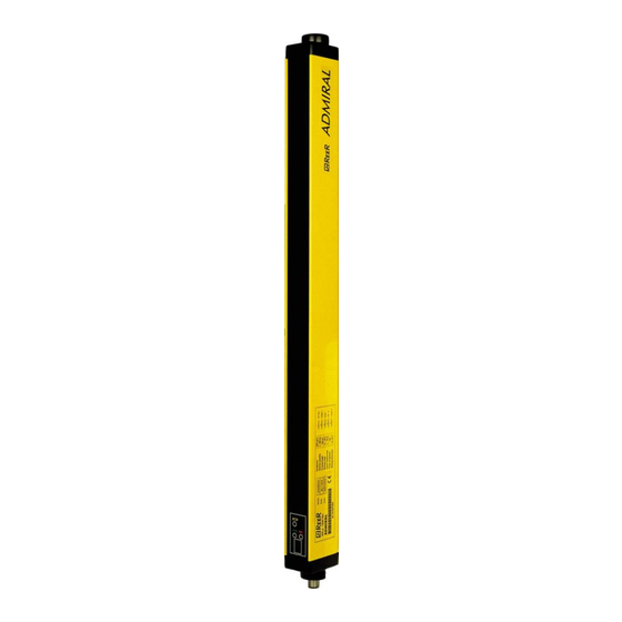
- Page 1 PHOTOELECTRIC SAFETY BARRIER ADMIRAL Ó Ó...
-
Page 2: Table Of Contents
PHOTOELECTRIC SAFETY BARRIER ADMIRAL INSTALLATION USE AND MAINTENANCE TABLE OF CONTENTS INTRODUCTION ........................2 OPERATION ......................... 3 INSTALLATION ........................4 POSITION ............................5 SAFETY DISTANCE CALCULATION ....................6 VERTICAL POSITION OF THE BARRIER ..................6 HORIZONTAL POSITION OF THE BARRIER ................8 ELECTRICAL CONNECTIONS .....................9 MULTIPLE SYSTEMS ........................ -
Page 3: Introduction
The two built-in safe static PNP outputs enable the barrier to be connected to the ADMIRAL SR safety modules or to a safety PLC or to another control system that satisfies the specific requirements and safety level of the application. -
Page 4: Operation
50 mm and 90 mm (protected height from 300 mm to 1800 mm) PROTECTION OF ARMS AND LEGS ADMIRAL is available also in the Multibeam configuration with the following lens pitch: – 500mm (2 beams), 400mm (3 beams), 300mm (4 beams). -
Page 5: Installation
ADMIRAL INSTALLATION Before installing the ADMIRAL safety system, make sure that: The safety system is only used as a stopping device and not as a machine control device. The machine control can be actuated electrically. All dangerous machine movements can be interrupted immediately. In particular, the machine stopping times must be known and, if necessary, measured. -
Page 6: Position
ADMIRAL The recommended Cf factors are shown in the table below: ENVIRONMENTAL CONDITION CORRECTION FACTOR Cf 0.25 Steam 0.50 Dust 0.50 Dense fumes 0.25 If the device is installed in places that are subject to sudden changes in temperature, the appropriate precautions must be taken in order to prevent the formation of condensation on the lenses, which could have an adverse effect on monitoring. -
Page 7: Safety Distance Calculation
ADMIRAL SAFETY DISTANCE CALCULATION The barrier must be installed at a distance that is greater than or equal to the minimum safety distance S, so that a dangerous point can only be reached after all hazardous machine movements have stopped (Figure 3). -
Page 8: Vertical Position Of The Barrier
ADMIRAL VERTICAL POSITION OF THE BARRIER 14 mm and 20 mm resolution models. These models are suitable for the protection of fingers. point of safety barrier danger 30 mm and 40 mm resolution models. These models are suitable for the protection of hands. -
Page 9: Horizontal Position Of The Barrier
ADMIRAL Multibeam Models. point of danger These models are suitable for the protection of the entire body and must not be used to protect safety barrier arms or legs. The minimum safety distance S is calculated according to the following formula:... -
Page 10: Electrical Connections
ADMIRAL ELECTRICAL CONNECTIONS WARNINGS Before making the electrical connections, make sure that the supply voltage complies with that specified in the technical data sheet. Emitter and Receiver units must be supplied with 24Vdc±20% power. The external power supply must comply with the standard EN 60204-1. - Page 11 ADMIRAL Connector pins EMITTER RECEIVER Figure 8 EMITTER NUMBER COLOR NAME MEANING Brown 24 VDC Power supply (positive) White 2 (see table 2) SEL RANGE/TEST1 Input 1 for range / TEST selection Blue 0 VDC Power supply (negative) Black 4 (see table 2)
- Page 12 ADMIRAL Example of connection of the ADMIRAL barrier to the ReeR AD SR1 safety module Refer to table 2, page 10 for the correct connection of pins 2 and 4 Figure 9 8540484 • 01/09/2016 • Rev.13...
- Page 13 ADMIRAL Examples of connection of ADMIRAL barrier Figure 10 8540484 • 01/09/2016 • Rev.13...
-
Page 14: Multiple Systems
The connection cables must follow a different route to that of the other power cables. MULTIPLE SYSTEMS When more than one ADMIRAL system is used, precautions must be taken to avoid optical interference between them: install units so that the beam emitted by the Emitter of one system can only be received by the relative Receiver. - Page 15 ADMIRAL Figure 13 After installing the system, check whether any reflecting surfaces intercept the beams, first in the centre and then in the vicinity of the Emitter and Receiver. During these operations, the red LED on the Receiver should never, for any reason, switch off.
-
Page 16: Use Of Deflection Mirrors
ADMIRAL USE OF DEFLECTION MIRRORS In order to protect or control areas that can be accessed from more than one side, in addition to the Emitter and Receiver, one or more deflection mirrors can be installed. These mirrors enable the optical beams generated by the Emitter to be deviated on one or more sides. -
Page 17: Mechanical Assembly And Optic Alignment
ADMIRAL MECHANICAL ASSEMBLY AND OPTIC ALIGNMENT The Emitter and the Receiver must be assembled opposite each other (at a distance specified in the technical data sheet). Use the fastening brackets and inserts supplied with the system to place the Emitter and the Receiver so that these are aligned and parallel to each other and with the connectors facing the same way. -
Page 18: Operation And Technical Data
ADMIRAL OPERATION AND TECHNICAL DATA SIGNALS COLOUR STATUS DISPLAY (4) CONDITION Yellow System activated. Initial TEST. Yellow L / H TEST condition Green Green Normal operation, low range Green Normal operation, high range FAULT CODE Malfunction * COLOUR STATUS DISPLAY (8) -
Page 19: Test Function
The minimum duration of the TEST function must be 80 msec. OUTPUTS STATUS The ADMIRAL features two static PNP outputs on the Receiver, the status of which depends on the condition of the protected area. The maximum load allowed is 500mA at 24VDC, which corresponds to a resistive load of 48. -
Page 20: Technical Specifications
ADMIRAL TECHNICAL SPECIFICATIONS TECHNICAL SPECIFICATIONS OF ADMIRAL BARRIERS 160 – 1810 Protected height 14 – 20 – 30 – 40 – 50 – 90 Resolutions 0 2 (low) Working range (selectable) 0 5 (high) 14mm models 0 6 (low) - Page 21 ADMIRAL 30 mm resolution models 1053 1203 1353 1503 1653 1803 Number of beams Response time Overall barrier ht. mm 1011 1161 1311 1461 1611 1761 1911 9,58E-9 1,05E-8 1,14E-8 1,24E-8 1,33E-8 1,42E-8 1,51E-8 1,61E-8 1,70E-8 1,79E-8 1,88E-8 1,98E-8 PFHd *...
-
Page 22: Dimensions (In Mm)
ADMIRAL DIMENSIONS (in mm) Figure 18 Emitter and Receiver Model 1050 1200 1350 1500 1650 1800 1001 1151 1301 1451 1601 1751 1901 1060 1210 1360 1510 1660 1810 (PROTECTED AREA) Mounting 2 LS Brackets with 2 mounting inserts 3 LS Brackets with 3 mounting inserts... - Page 23 ADMIRAL Figure 20 LL and LH TYPE fastening brackets (optional) Inserts M8 Model SP100S SP300S SP400S SP600S SP700S SP900S 1060 SP1100S 1230 SP1200S 1400 SP1300S 1450 SP1500S 1600 SP1600S 1750 SP1800S 1900 Figure 21 Fastening brackets for deviation mirrors Figure 22 Deviation mirrors 8540484 •...
-
Page 24: Checkouts And Maintenance
If the yellow weak signal LED on the Receiver switches on (LED 5 in Figure 16), check that: – the front surfaces are clean; – the Emitter and Receiver are aligned correctly. If the LED stays on, contact the ReeR service department. 8540484 • 01/09/2016 • Rev.13... -
Page 25: Troubleshooting
Check the connection of terminals 2 and 4 (SEL RANGE/TEST) on RANGE/TEST signals the connector carefully. Internal failure relating to the add-on boards Internal failure relating to the Return the equipment to ReeR laboratories for repair. microcontroller boards Internal failure RECEIVER CODE DIAGNOSIS... - Page 26 In any case, when faced with a system stoppage, switch the system off and then on again, to exclude any occasional electromagnetic disturbances. Should the problem persist after carrying out the checks described above, contact ReeR’s service department. In case of continued malfunctioning: ...
-
Page 27: Spare Parts
ADMIRAL SPARE PARTS MODEL ARTICLE CODE AD SR1 ADMIRAL AD SR1 Safety Relay 1330900 AD SR2 ADMIRAL AD SR2 Safety Relay 1330901 Straight 5-pin M12 female connector, 5 m cable 1330950 CD95 90° 5-pin M12 female connector, 5 m cable... -
Page 28: Guarantee
ADMIRAL GUARANTEE All new ADMIRAL systems are guaranteed by ReeR for a period of 12 (twelve) months under normal working conditions, against defects due to faulty materials and workmanship. During the aforesaid period, ReeR promises to replace faulty parts free of charge. This guarantee covers both material and labour. - Page 29 REER SpA via Carcano 32 10153 – Torino Italy dichiara che le barriere fotoelettriche ADMIRAL sono Dispositivi Elettrosensibili di Sicurezza (ESPE) di : Tipo 4 (secondo la Norma CEI EN 61496-1:2005; CEI EN 61496-2:2007) SILCL 3 (secondo la Norma IEC 62061:2005 + A1:2012) ...
Need help?
Do you have a question about the ADMIRAL and is the answer not in the manual?
Questions and answers