
Related Manuals for Siemens simatic PC 577


Summary of Contents for Siemens simatic PC 577
- Page 1 Operating Instructions Edition 04/2006 SIMATIC Industrial PC SIMATIC Panel PC 577 Industrial PC Panel PC 577 simatic DOCUMENTATION DOCUMENTATION...
- Page 3 Preface Safety instructions and general notes Description SIMATIC Planning use Industrial PC SIMATIC Panel PC 577 Installation Connecting Operating Instructions Commissioning Operation and configuration Operating Integration in TIA Servicing and maintenance Alarm, error and system messages Troubleshooting and FAQs Technical specifications Detailed descriptions Appendix Release 04/2006...
-
Page 4: A5E00798484
Trademarks All names identified by ® are registered trademarks of the Siemens AG. The remaining trademarks in this publication may be trademarks whose use by third parties for their own purposes could violate the rights of the owner. -
Page 5: Operating Instructions, Release 04/2006,
Preface This manual Purpose of the manual This manual provides information based on the requirements defined by DIN 8418 regarding mechanical engineering documentation. This information relates to the device, its place of use, transport, storage, installation, use and maintenance. This manual is intended for the following target groups: •... - Page 6 The following links will bring you directly to the technical documentation collection for SIMATIC products and systems in the languages German, English, French, Italian and Spanish. • SIMATIC Guide Technische Dokumentation in Deutsch: http://www.ad.siemens.de/simatic/portal/html_00/techdoku.htm • SIMATIC guide to technical documentation in English: http://www.ad.siemens.de/simatic/portal/html_76/techdoku.htm Conventions...
- Page 7 Preface Trademarks All names labeled with ® symbol are registered trademarks of Siemens AG. Other names used in this documentation may be trademarks, the use of which by third parties for their own purposes could violate the rights of the owner.
- Page 8 Technical support You can reach the technical support for all A&D products via the support request form on the web: • http://www.siemens.com/automation/support-request • Phone: + 49 180 5050 222 • Fax: + 49 180 5050 223 Additional information about our technical support is available in the Internet at: http://www.siemens.com/automation/service...
-
Page 9: Table Of Contents
Table of contents Preface ..............................iii Safety instructions and general notes ..................... 1-1 Safety instructions........................1-1 General information, download "Panel PC" ................1-5 Description.............................. 2-1 Application features ........................2-1 Design ............................2-2 Technical features........................2-3 Planning use............................3-1 Overview ............................ 3-1 Unpacking and checking the delivery .................. - Page 10 Table of contents Connecting ............................. 5-1 Overview ............................ 5-1 Interfaces............................ 5-3 5.2.1 Front interfaces .......................... 5-3 5.2.2 Rear interfaces........................... 5-4 Connecting peripherals ......................5-6 5.3.1 Overview ............................ 5-6 5.3.2 Connecting a monitor ......................... 5-6 5.3.3 USB ............................5-7 Connecting the power supply..................... 5-9 Uninterruptible AC power supplies...................
- Page 11 Table of contents Integration in TIA ............................ 9-1 Industrial communications ......................9-1 PROFIBUS/MPI interface and WinAC card ................9-2 Servicing and maintenance........................10-1 10.1 Servicing ..........................10-1 10.2 Removing and installing hardware components ..............10-3 10.2.1 Repairs............................. 10-3 10.2.2 Opening the device ........................10-5 10.2.3 View of internal components with open device................
- Page 12 Table of contents Detailed descriptions ..........................14-1 14.1 Overview of the Panel PC 577 motherboard ................14-1 14.2 Riser card ..........................14-2 14.3 Touch sensor ........................... 14-3 14.4 System resources ........................14-5 14.4.1 Currently allocated system resources..................14-5 14.4.2 Interrupt assignment ........................ 14-6 14.5 BIOS setup ..........................
-
Page 13: Safety Instructions And General Notes
Safety instructions and general notes Safety instructions Warning Emergencies In the event of a device fault, remove the mains connector immediately. Inform the customer service personnel responsible. Malfunctions can occur when the operator controls or power cable are damaged or when liquids or foreign objects penetrate the device. Caution Please observe the safety instructions on the back of the cover sheet of this documentation. - Page 14 Safety instructions and general notes 1.1 Safety instructions System expansions Only install system expansion devices designed for this device. The installation of other expansions can damage the system and violate the radio-interference suppression regulations. Contact your technical support team or where you purchased your PC to find out which system expansion devices may safely be installed.
- Page 15 Safety instructions and general notes 1.1 Safety instructions ESD guidelines Modules containing electrostatic sensitive devices (ESDs) can be identified by the following label: Strictly follow the guidelines mentioned below when handling modules which are sensitive to ESD: • Always discharge your body´s static electricity before handling modules which are sensitive to ESD (for example, by touching a grounded object).
- Page 16 Safety instructions and general notes 1.1 Safety instructions Electrical connection Warning Disconnect the device from the mains before every intervention. Do not touch power cables or data transmission cables during electrical storms and do not connect any cables. High frequency radiation Caution Unintentional operating situations High frequency radiation, e.g.
-
Page 17: General Information, Download "Panel Pc
Safety instructions and general notes 1.2 General information, download "Panel PC" General information, download "Panel PC" Overview Caution The device is approved for operation in closed rooms only. The guarantee is void if this stipulation is ignored. Avoid extreme environmental operating conditions. Protect your device against dust, moisture and heat. - Page 18 Please check regularly whether updates and hotfixes are available for download to your device. Downloads are available on the Internet at "http://www.siemens.com/asis" under "Support". Click on "Tools & Demosoftware" on "Overview Panel PCs". Using the global search function, you can then also search for any downloads you require.
- Page 19 Safety instructions and general notes 1.2 General information, download "Panel PC" Safety-relevant applications Warning Maloperation Do not perform safety-relevant functions of the user software with the touch screen. Chemical resistance Caution Adhere to the information regarding chemical resistance. Please refer to the "Tools & Demosoftware"...
- Page 20 Safety instructions and general notes 1.2 General information, download "Panel PC" Burn-in effect on TFT displays A permanent picture with bright images can lead to a burn-in effect on the TFT LCD. If a screen saver is activated, please observe the following: •...
-
Page 21: Description
Description Application features Introduction The Panel PC 577 provides a high standard of quality based on the protection type of the control unit, high-level EMC and CE certification for industrial application. The device is designed for 24 hour operation. Further information is available in the section "Ambient and environmental conditions of the "Technical data"... -
Page 22: Design
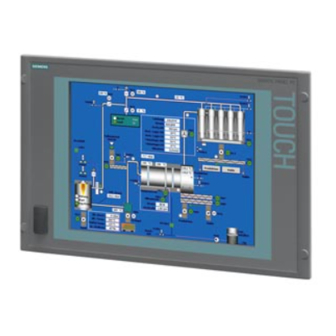
Description 2.2 Design Design The device serves as a base for PC-based HMI devices, the Panel PCs. The Panel PC 577 fulfills the basic requirements for industrial compatibility and provides high performance at a low price. The device consists of the control unit with a key or touch panel and the computer unit. The control unit is screwed to the back of the computer unit. -
Page 23: Technical Features
Description 2.3 Technical features Technical features General features Processor - Intel® Pentium 4 2.4 GHz - Intel® Celeron 2.0 GHz Chipset Intel 865G Main memory 256 MB = 2 x 128 MB SDRAM or 1 x 256 MB SDRAM 512 MB = 2 x 256 MB SDRAM 4 slots, expandable to 4 GB maximum Uppermost slot is suitable for WinAC Slot Slots for add-ons... - Page 24 Description 2.3 Technical features Interfaces Installed via expansion cards: PROFIBUS / MPI CP 5611-compatible (not included in the scope of supply) Ethernet LAN 10/100/1000 Mbps 4x USB 2.0 high current, external 2x USB 2.0 high current available, internal via male connector 1x USB 2.0 high current, front mounted Serial interfaces COM1 V.24...
- Page 25 Description 2.3 Technical features SIMATIC Panel PC 577 Operating Instructions, Release 04/2006, A5E00798484-01...
- Page 26 Description 2.3 Technical features SIMATIC Panel PC 577 Operating Instructions, Release 04/2006, A5E00798484-01...
-
Page 27: Planning Use
Planning use Overview Introduction This section describes the first steps after unpacking, the permitted mounting positions and the fixation. This section describes the necessary considerations for EMC. Field of application The Panel PC is an industry-standard PC platform for demanding tasks in the field of PC- based automation. -
Page 28: Unpacking And Checking The Delivery
Planning use 3.2 Unpacking and checking the delivery Unpacking and checking the delivery Procedure 1. Please check the packaging material for transport damage upon delivery. 2. If any transport damage is present at the time of delivery, lodge a complaint at the shipping company in charge. - Page 29 Planning use 3.2 Unpacking and checking the delivery Warning Risk of damage Do not transport the device when it is mounted. During transport, use the hard disk transport lock (if present). The device is approved for use with the following operating systems: Approvals •...
-
Page 30: Make Note Of Identification Data
Planning use 3.3 Make note of identification data Make note of identification data Procedure 1. Write down the Microsoft Windows product key of the Certificate of Authenticity COA in the table at the end of this section. The product key can be found on the back of the device. -
Page 31: Emc Directive
The device is designed as a built-in model with front-sided IP65 degree of protection. Ensure compliance with the EN 61000-4-2 standard by installing the device in grounded metal cabinets, e.g. 8 MC cabinets, Siemens catalog NV21. Note For additional information about EMC requirements, refer to the Technical data section. -
Page 32: Mounting Positions And Fastening
Planning use 3.5 Mounting positions and fastening Mounting positions and fastening 3.5.1 Installation instructions Before mounting the device, read the following general notes relating to installation. Warning Dangerous Voltage Isolate the power supply to the control cabinet before opening it. Ensure that the power to the control cabinet cannot be turned on accidentally. - Page 33 Planning use 3.5 Mounting positions and fastening • Also provide enough free space to add on to the device. • Equip the control cabinet with struts for stabilizing the mounting cut-out. Install struts where necessary. • Avoid extreme environmental operating conditions. Protect your device against dust, moisture and heat.
-
Page 34: Permitted Mounting Positions
Planning use 3.5 Mounting positions and fastening 3.5.2 Permitted mounting positions Approval Only certain mounting positions are approved for the device. Figure 3-2 Permitted mounting position The device can be mounted in a vertical position with deviations between +5° and -5° in the given directions. -
Page 35: Degree Of Protection
This degree of protection is assured when fixed using screws and the mounting components for 19" rack accessories. Note For screw fixing of the 19" touch panel front, a backing plate is available as an accessory. For further information, see "http://mall.ad.siemens.com/". SIMATIC Panel PC 577 Operating Instructions, Release 04/2006, A5E00798484-01... -
Page 36: Mounting Cut-Out
Planning use 3.6 Mounting cut-out Mounting cut-out 3.6.1 Selecting and creating the mounting cut-out Requirement The degree of protection suitable to the field of application and thereby the mounting method have been selected. Procedure 1. Follow the installation instructions. 2. Select a location suitable for installation, taking into account the installation instructions and the chosen mounting position. -
Page 37: Dimensions
Planning use 3.6 Mounting cut-out 3.6.2 Dimensions The following illustration shows the dimensions for the mounting cut-out. You can also obtain these dimensions from the mounting template supplied with the device. Figure 3-3 Drill holes for the screws and pressure points for the clamp screws Drill hole for screw attachment Clamp Pressure points for clamp... -
Page 38: Table 3-1 Dimensions For The Mounting Cut-Out In Mm
Planning use 3.6 Mounting cut-out Table 3-1 Dimensions for the mounting cut-out in mm Control units Tolerance +1 ±0.2 ±0.2 ±0.5 ±0.5 ±0. ±0.5 +1 ±1 ±1 ±1 ±1 ±1 ±1 ±1 ±1 ±1 panels 12" TFT — — — —... -
Page 39: Installation
Installation Securing with clamps Scope Skip this step if you have selected "screw mounting." Note The 12" touch screen variant can only be fixed in place using clamps. Requirement • The mounting cut-out has been completed. • Clamps are readily available in the accessories. Clamps and setscrews are included in the contents of delivery. -
Page 40: Securing With Screws
Installation 4.2 Securing with screws Securing with screws Scope Skip this step if you have selected "clamp mounting." Notice Securing with screws is not possible with the 12" touch screen variant. For securing the 19'' touch screen variant with screws, you will need the accessory with MLFB No. - Page 41 Installation 4.2 Securing with screws Procedure 1. Follow the installation instructions. 2. Drill suitable holes at the prepared mounting cut-out in accordance with the specifications for L4 and L5, as shown in the mounting cut-out in the dimensions. 3. Carefully drill the respective holes in the control unit at the designated location (1) from the rear.
-
Page 42: Dimensions
Installation 4.3 Dimensions Dimensions The mounting depth increases by 28 mm when a DVD-ROM drive is installed in the device. Refer to the dimensional drawings in the "Technical specifications" section for the exact measurements. SIMATIC Panel PC 577 Operating Instructions, Release 04/2006, A5E00798484-01... -
Page 43: Connecting
Connecting Overview Introduction Once you have mounted the device, connect it. Warning Do not touch power cables or data transmission cables during electrical storms and do not connect any cables. Unplug the mains connector from the socket to be sure the electricity is disconnected. Caution Connection sequence Follow the described sequence when connecting the device to avoid damaging it. - Page 44 Connecting 5.1 Overview Procedure 1. Connect the equipotential bonding. 2. Connect peripherals: – Connect an external monitor if desired. – Connect the PS/2 mouse. – Connect the PS/2 keyboard. – Connect a USB device such as a USB mouse if desired. –...
-
Page 45: Interfaces
Connecting 5.2 Interfaces Interfaces 5.2.1 Front interfaces Introduction A USB interface is located on the front side. For more information, please refer to the chapter "Operation." Attach an external keyboard or an external mouse, for example, to the USB interface. The front-side USB interface supports the standard USB 2.0. Caution Wait at least 10 seconds between the unplugging and replugging of USB devices. -
Page 46: Rear Interfaces
Connecting 5.2 Interfaces 5.2.2 Rear interfaces Interfaces Arrangement of the interfaces Item Name Description KEYBOARD Connection for a PS/2 keyboard Mouse Connection for a PS/2 mouse USB 2.0 Connection for USB devices COM 1 Serial interface, 9-pin Sub-D connector LPT 1 Parallel interface, 25-pin sub D socket VGA connection... -
Page 47: Power Supply
Connecting 5.2 Interfaces Power supply Position of the IEC power connector Description IEC power connector (2) for the AC power supply to the device. The maximum permitted power supply range is 120 V AC to 230 V AC. On / Off switch (1) Note You can also switch on the device using the soft power key. -
Page 48: Connecting Peripherals
2:2001. Use shielded cables and metal connectors to connect peripherals. Otherwise, the specified standards and specifications declared by Siemens AG are no longer valid. Secure the plugs of the interface cables to the device housing with screws. This improves the electrical shielding. -
Page 49: Usb
Connecting 5.3 Connecting peripherals 5.3.3 Introduction Commercially available USB peripherals can be easily and flexibly connected via the USB interface. For example, you can connect an external USB keyboard and a USB mouse. If the USB keyboard has a USB interface, you can connect other USB peripherals, such as a USB mouse, directly to the keyboard. - Page 50 Connecting 5.3 Connecting peripherals Connecting USB devices Caution Wait at least 10 seconds between removal and reconnection of USB devices. This also applies to control units with touch screens, especially for touch operation. Notice When using standard USB peripherals, please bear in mind that their EMC immunity level is frequently designed for office applications only.
-
Page 51: Connecting The Power Supply
Connecting 5.4 Connecting the power supply Connecting the power supply Principle The device can be optionally operated on 110 or 230 V AC systems. The device features an automatic voltage switch and a power switch. Caution Do not touch power cables or data transmission cables during electrical storms and do not connect any cables. - Page 52 Connecting 5.4 Connecting the power supply For USA and Canada: A UL-listed power supply cable must be used in the United States and Canada. 110V power supply Use a flexible cable with the following characteristics: • UL approval • Type SJT with three conductors •...
-
Page 53: Uninterruptible Ac Power Supplies
UPS characteristics are described and classified in EN 50091-3 and IEC 62040-3. Note More information is available on the Internet at "www.ad.siemens.de" under "Products & Solutions." Click on "Service & Support" under "Services" and search for the article ID "17241008" on the "Product Support" page. At the end of the article there is a link to the document, "UPS Classification Based On Operational Performance". -
Page 54: Connecting The Equipotential Bonding
Connecting 5.6 Connecting the equipotential bonding Connecting the equipotential bonding A low-resistance ground connection ensures that interference signals generated by external power supply cables, signal cables or cables to the I/O modules are safely discharged to ground. The equipotential bonding connection of the device is located at the connection elements of the computer unit and is identified by the following symbol: Figure 5-1 Equipotential bonding... - Page 55 Connecting 5.6 Connecting the equipotential bonding Avoiding differences in potential Differences in potential arise between separated system parts, which in some cases lead to high equalization currents. This situation may arise if the cable shielding is terminated at both ends and grounded at different system parts. Potential differences can be caused, for example, by different power inputs.
- Page 56 Connecting 5.6 Connecting the equipotential bonding SIMATIC Panel PC 577 5-14 Operating Instructions, Release 04/2006, A5E00798484-01...
- Page 57 Connecting 5.6 Connecting the equipotential bonding SIMATIC Panel PC 577 5-15 Operating Instructions, Release 04/2006, A5E00798484-01...
-
Page 59: Commissioning
Commissioning Removing the transport lock for the hard disk Note Not every device has a hard disk transport lock. To enhance the ruggedness of the SIMATIC Panel PC 577 during shipping, the device is fitted with a transport lock for the hard disk. This comprises two knurled screws that clamp the hard disk to prevent undesirable vibrations. - Page 60 Commissioning 6.1 Removing the transport lock for the hard disk Removing the transport lock for the hard disk Procedure for removing the transport lock for the hard disk Unscrew 2 knurled screws (1) by hand Screw the knurled screws into the nuts on the rear of the device for safe-keeping. Notice Risk of damage If you do not remove the hard disk transport lock before starting up the device, the SIMATIC...
-
Page 61: Overview
Peripheral devices • Use shielded cables and metal connectors to connect peripherals. Otherwise, the specified standards and specifications declared by Siemens AG are no longer valid. Secure the plugs of the interface cables to the device housing with screws. This improves the electrical shielding. - Page 62 Commissioning 6.2 Overview Procedure 1. Switch on the device. 2. Install Microsoft Windows operating system. 3. Install the applications and drivers. SIMATIC Panel PC 577 Operating Instructions, Release 04/2006, A5E00798484-01...
-
Page 63: Switching On The Device
Commissioning 6.3 Switching on the device. Switching on the device. Procedure 1. Plug the mains connector of the supplied power supply cable in the AC power supply connector of the device. 2. Screw on the lock for the mains connector (1). Figure 6-1 Lock mains connector 3. - Page 64 Commissioning 6.3 Switching on the device. Self-test After connection to the power supply, the device performs a self test. During the self test, the message "Press <F2> to enter SETUP" appears briefly. When the self-test is finished, the operating system will be loaded. SIMATIC Panel PC 577 Operating Instructions, Release 04/2006, A5E00798484-01...
-
Page 65: Setting Up The Microsoft Windows Operating System
Commissioning 6.4 Setting up the Microsoft Windows operating system Setting up the Microsoft Windows operating system Introduction The setup wizard appears immediately following the startup of the device. The wizard is used to set the parameters of the operating system. Note The dialogs of the setup wizards differ slightly in some places for the Windows 2000 Professional and Windows XP Professional operating systems. -
Page 66: Installing Applications And Drivers, Touch-Base
Commissioning 6.5 Installing applications and drivers, Touch-Base Installing applications and drivers, Touch-Base Introduction After the device is restarted, different dialogs appear on the screen. Drivers and applications can be installed from these dialogs. Additional hardware and software components You can install and configure additional hardware and software components such as a network. - Page 67 Commissioning 6.5 Installing applications and drivers, Touch-Base Procedure 1. In the "Panel Wizard" dialog, click the type of panel that corresponds to your device. Figure 6-2 Panel Wizard, selection of the panel type 2. In the "Panel Wizard Touch" dialog, click on the screen size that corresponds to your device.
- Page 68 Commissioning 6.5 Installing applications and drivers, Touch-Base Figure 6-3 Panel Wizard Touch, selection of the screen size The next step only applies to control units with touch screen panels. Once the screen size is selected, the wizard will search for new hardware, the touch controller.
-
Page 69: Operation And Configuration
Commissioning 6.5 Installing applications and drivers, Touch-Base 3. Briefly touch the touch screen at every cross hair. Figure 6-4 Touch screen calibration 4. The following only applies to control units with key panels: Exit the operating system session and restart the device. Otherwise the "Security features" from "KeyTools" will not be activated. -
Page 70: Operating
Commissioning 6.5 Installing applications and drivers, Touch-Base The installation of the drivers and applications is complete. Further information is available in the "Operation and configuration" chapter of the operating instructions under the section, "Additional drivers and applications." Notice After starting up your device, find out more about the particulars of the operating system in the chapter "Start-up"... -
Page 71: Notes About New Installation Of Windows 2000
Updates will then no longer be performed automatically on the device via the Internet. Notice When the check-box is activated, updates will be installed automatically on the device via the Internet even when they have not been released by Siemens AG. SIMATIC Panel PC 577 6-13... - Page 72 Commissioning 6.6 Notes about new installation of Windows 2000 SIMATIC Panel PC 577 6-14 Operating Instructions, Release 04/2006, A5E00798484-01...
-
Page 73: Operation And Configuration
Caution Use shielded cables and metal connectors to connect peripherals. Otherwise, the specified standards and specifications declared by Siemens AG are no longer valid. Secure the plugs of the interface cables to the device housing with screws. This improves the electrical shielding. - Page 74 Operation and configuration 7.1 Normal operation Procedure Warning Danger of maloperation! The following applies to external input devices or combinations of external input devices and control units with key panels: Ambiguous key codes can cause serious malfunctions of the application program. Always activate the "Security features"...
- Page 75 Operation and configuration 7.1 Normal operation Switching off the device Shut down the operating system correctly before switching off the device. Caution Wait for the display to go dark. Then switch off the power switch of the device. Warning Always pull out the power cable to isolate the device from the mains. SIMATIC Panel PC 577 Operating Instructions, Release 04/2006, A5E00798484-01...
-
Page 76: Additional Drivers And Applications
Operation and configuration 7.2 Additional drivers and applications Additional drivers and applications 7.2.1 Overview The necessary drivers and applications are contained in the supplied "Documentation and Drivers" CD. Note The supplied drivers and applications have been system-tested and are approved for this device. -
Page 77: Setting The Touch Screen
Operation and configuration 7.2 Additional drivers and applications 7.2.2 Setting the touch screen Call • Start menu "Start", command "Programs > UPDD > Settings" Function Recalibrates the touch screen. If the touch screen does not react as expected when touched, repeat the calibration. To do this, first activate the 25 point calibration and then calibrate the touch screen. - Page 78 Operation and configuration 7.2 Additional drivers and applications Special features Note When the edges of the touch screen are used intensively, it is recommended that 25 point calibration is performed instead of the 9 point calibration. Warning Maloperation If you touch the touch screen while the screen saver is active, the SIMATIC process visualization software, e.g.
-
Page 79: Keytools
Operation and configuration 7.2 Additional drivers and applications 7.2.3 KeyTools Call Start menu "Start", command "Settings > Control panel > SIMATIC Key Tools" Function SIMATIC KeyTools is one selection of the applications for Panel PC. With it, key codes which are sent from the key panel of the control unit are adjusted. A description of the "KeyTools"... -
Page 80: Systemguard
Function SystemGuard indicates temperatures, fan speeds and voltages. Notice SystemGuard is a freeware tool for which Siemens AG offers no technical support. Observe the notes in the online help of the application. Example In the "Temperatures" tab you can see the current temperature of the CPU for the first and a second processor and the internal temperature of the device. -
Page 81: Touchinput
Operation and configuration 7.2 Additional drivers and applications 7.2.5 TouchInput Call "TouchInput" symbol on the desktop. Function TouchInput provides a screen keyboard. On the screen keyboard, the characters are entered directly on the touch screen or with the mouse. Figure 7-3 TouchInput SIMATIC Panel PC 577 Operating Instructions, Release 04/2006, A5E00798484-01... -
Page 82: Checklanguageid
Operation and configuration 7.2 Additional drivers and applications 7.2.6 CheckLanguageID Scope The following applies to Windows 2000 Professional Multi-Language and Windows XP Professional Multi-Language. Call c:\drivers\checklang\checklangid.exe or reinstallation from the "Documentation and Drivers" Function "CheckLanguageID" displays the currently installed languages. Figure 7-4 CheckLanguageID •... -
Page 83: Multilingual Settings For The Operating System
Operation and configuration 7.2 Additional drivers and applications 7.2.7 Multilingual settings for the operating system Windows MultiLanguage MUI operating system enables users to set the language of the GUI to their individual preference. Some elements are not localized, however, and remain in the original language of the system - English. - Page 84 Operation and configuration 7.2 Additional drivers and applications SIMATIC Panel PC 577 7-12 Operating Instructions, Release 04/2006, A5E00798484-01...
-
Page 85: Operating
Operating Operator controls On / Off switch On / Off switch Description The device is on when the power switch (1) is in position "0". Voltage is supplied to the device even when it is switched off. Warning The On / Off switch does not disconnect the device from mains. SIMATIC Panel PC 577 Operating Instructions, Release 04/2006, A5E00798484-01... - Page 86 Operating 8.1 Operator controls "Soft power" key "Soft power" key Description The soft power key (1) can trigger two shutdown functions during active operation: 1) Correct shutdown of the operating system and shutdown of the device To perform this function, press the key briefly with a pointed object. 2) Immediate switch-off of the device without correct shutdown of the operating system This function is used to shut down the device when it no longer responds.
-
Page 87: Operator Controls On Key Panels
Operating 8.2 Operator controls on key panels Operator controls on key panels 8.2.1 Overview The device has the following keypads: • 2 x 8 vertical keypads with softkey functions • 2 x 10 horizontal keypads with function keys F1 -F20 The number of keys, their labeling and function is the same on all key panels. -
Page 88: Keyboard
Operating 8.2 Operator controls on key panels 8.2.2 Keyboard Principle The layout of the membrane keyboard is "English/USA international." Warning Maloperation If you activate several keys simultaneously, a malfunction on the device cannot be excluded. Activate function keys and softkeys only in sequence! Use "KeyTools" as described in the chapter "Additional drivers and applications."... - Page 89 Operating 8.2 Operator controls on key panels Function keys and softkeys The softkeys are arranged on the left and on the right, and the function keys in a double row below the display. Figure 8-2 Function keys and softkeys Control keys The control keys activate editing functions and control functions in different applications: Backspace Open Help...
- Page 90 Operating 8.2 Operator controls on key panels Numeric keys Enter the numerals "0" to "9" and special characters, e.g. the decimal point, using the pre- defined assignment of the numeric keys. Figure 8-3 Numeric keys Enter special characters, arithmetic signs and signs Special characters, arithmetic signs and signs are also assigned to most of the alphanumeric and numeric keys.
-
Page 91: Labeling Function Keys And Softkeys
Operating 8.2 Operator controls on key panels External keyboards The keyboard layout has been set to "English/USA international." If you use a keyboard with a layout other than the "English/USA international" layout, the key codes of the internal and external keyboards might no longer correspond. 8.2.3 Labeling function keys and softkeys Scope... - Page 92 Operating 8.2 Operator controls on key panels Figure 8-4 12" device: Rear of the control unit with connectors and slots for the labeling strips Figure 8-5 15" device: Rear of the control unit with connectors and slots for the labeling strips SIMATIC Panel PC 577 Operating Instructions, Release 04/2006, A5E00798484-01...
-
Page 93: Operator Controls Of The Touch Screen Panels
Operating 8.3 Operator controls of the touch screen panels Operator controls of the touch screen panels 8.3.1 Overview The 12", 15" and 19" variants differ in their dimensions and the size of the display. The 12'' and 19'' variants do not have side drill hole covers. The following figure is therefore only an example using the front view of the 15"... -
Page 94: Touch Screen
Operating 8.3 Operator controls of the touch screen panels 8.3.2 Touch screen The display is sensitive to touch and application-specific surface elements, e.g. a button, appear on the screen. By tapping the button with your finger, the function assigned to the button is activated. -
Page 95: Dvd-Rom Drive
Operating 8.4 DVD-ROM drive DVD-ROM drive Introduction The DVD-ROM or DVD burner drive is used to install software during commissioning or when servicing a device. Figure 8-7 CD-ROM drive Access LED Eject key Emergency removal aperture Tray Emergency removal An emergency removal involves removing a CD when the tray is blocked or there is no power for the drive. -
Page 96: Transferring Authorizations
Operating 8.5 Transferring authorizations Transferring authorizations Note The device has no floppy disk drive. Therefore, transfer the authorizations for SIMATIC HMI software from a USB floppy disk drive. The following devices have been tested: SINUMERIK FLOPPY DISK DRIVE, order number 6FC5235-0AA05-1AA2 Caution The USB floppy disk drive is only suitable when mounted in a control cabinet. -
Page 97: Integration In Tia
You require suitable software for this: STEP7, WinCC, ProTool, WinCC flexible, WinAC, SIMATIC NET. Profinet Additional information For further information, refer to the catalog and to the online ordering system of Siemens A&D. Internet address: https://mall.ad.siemens.com SIMATIC Panel PC 577... -
Page 98: Profibus/Mpi Interface And Winac Card
Integration in TIA 9.2 PROFIBUS/MPI interface and WinAC card PROFIBUS/MPI interface and WinAC card Note You can use a CP 5613 communication module for the PROFIBUS/MPI interface. A PROFIBUS/MPI interface is also provided on WinAC cards. You can find further information in the documentation for the CP 5613 communication module and in the "Servicing and maintenance"... -
Page 99: Servicing And Maintenance
Servicing and maintenance 10.1 Servicing 10.1 Scope of maintenance When working in areas where there is dust that may be hazardous to functionality, the device must be operated in a control cabinet with a heat exchanger or with suitable supply air. - Page 100 Servicing and maintenance 10.1 Servicing Chemical resistance Caution Adhere to the information regarding chemical resistance of the panel front. Please refer to the "Tools & Demosoftware" Internet site for more information. Enter "Chemical resistance" as the search term. The available articles are displayed. Procedure 1.
-
Page 101: Removing And Installing Hardware Components
Notice Note the ESD instructions. Limitation of liability All technical data and licenses apply only to upgrades approved by SIEMENS. No liability can be accepted for impairment of functions caused by the use of third-party devices or components. SIMATIC Panel PC 577... - Page 102 Servicing and maintenance 10.2 Removing and installing hardware components Tools You can perform all installation tasks on the device using Torx T6, Torx T10, and Torx T20 screwdrivers and a Philips screwdriver. SIMATIC Panel PC 577 10-4 Operating Instructions, Release 04/2006, A5E00798484-01...
-
Page 103: Opening The Device
Servicing and maintenance 10.2 Removing and installing hardware components 10.2.2 Opening the device Warning Do not touch power cables or data transmission lines during electrical storms and do not connect any cables. Caution Warranty period Within the warranty time, you are only allowed to install expansions for memory and expansion card modules. - Page 104 Servicing and maintenance 10.2 Removing and installing hardware components Opening the device Accessing expansion modules Remove the four screws (1). Remove the 2 screws (2). Lift the lid up and remove it. SIMATIC Panel PC 577 10-6 Operating Instructions, Release 04/2006, A5E00798484-01...
- Page 105 Servicing and maintenance 10.2 Removing and installing hardware components Access to memory modules, processor, heat sinks, back-up battery and power supply Remove the 3 screws (1). Remove 2 screws (2) from the CD-ROM drive. Tilt the cover (1) CD-ROM drive (2) upward.
- Page 106 Servicing and maintenance 10.2 Removing and installing hardware components Closing the device Caution Avoid crimping the cables When closing the housing cover, make sure you do not crimp a cable between the fan and heat sink and that no cable is in contact with the heat sink. Figure 10-1 Closing the device, cable arrangement SIMATIC Panel PC 577...
-
Page 107: View Of Internal Components With Open Device
Servicing and maintenance 10.2 Removing and installing hardware components 10.2.3 View of internal components with open device The following components can be seen when the device is open: Figure 10-2 Components Power supply Processor with fan Slots for memory modules Hard disk Back-up battery under the ribbon cable Motherboard... -
Page 108: Removing/Installing Memory Modules
Servicing and maintenance 10.2 Removing and installing hardware components 10.2.4 Removing/installing memory modules Memory expansion The motherboard is equipped with 4 slots for memory modules. This enables you to expand the memory capacity of the device to a maximum of 3 GB. Depending on the variant you have ordered, the basic configuration may include 2 X 128 MB SDRAM or 2 X 256 MB DDR400. - Page 109 Servicing and maintenance 10.2 Removing and installing hardware components Removing a memory module Steps for removing a memory module Open the device. Snap the interlocks (1) to the side. Pull the memory module (2) upwards out of the slot. Close the device. Display of the current memory expansion Changes to the memory expansion are automatically detected.
-
Page 110: Pci/Winac Cards
Servicing and maintenance 10.2 Removing and installing hardware components 10.2.5 PCI/WinAC cards 10.2.5.1 Notes on the modules Notes on module specifications The device is designed for use with modules conforming to AT/PCI specifications. PCI modules with 5 V and 3.3 V supply voltage can be operated. Note about long PCI modules Before long PCI modules can be inserted into the guide rails, they must be fitted with an extender (this should be supplied with the long PCI board). -
Page 111: Installing Expansion Modules
Servicing and maintenance 10.2 Removing and installing hardware components 10.2.5.2 Installing expansion modules PCI card Steps for installing a PCI card: 1 Open the device. 2 Remove the relevant steel slot cover (1) 3 Insert the expansion module (2) into the relevant slot. - Page 112 Servicing and maintenance 10.2 Removing and installing hardware components WinAC card Further information is available in the section "WinAC card" of the "Integration in TIA" chapter. Steps for installing a WinAC card Open the device. Remove the frame with the card retainer (2, 3): remove the 2 retaining screws (1) of the threads from the outside.
- Page 113 Servicing and maintenance 10.2 Removing and installing hardware components Steps for installing a WinAC card Place the WinAC cover plate (1) over the WinAC card from the right. Ensure that the WinAC card is inserted in the guide rail (2). Insert the WinAC card into the upper slot.
- Page 114 Servicing and maintenance 10.2 Removing and installing hardware components Steps for installing a WinAC card Secure the frame with the (2, 3) card retainers Make sure that the frame is • connected to the device from the outside. To adapt to different cards, the •...
-
Page 115: Drives
Servicing and maintenance 10.2 Removing and installing hardware components 10.2.6 Drives 10.2.6.1 Removing and installing a DVD-ROM drive Procedure 1. Loosen the 4 screws (1). Figure 10-3 Drive with housing 2. To remove the housing of the drive, hold down the base plate (2) of the drive securely and slide the housing (3) to the right until the eyes (4) are free. - Page 116 Servicing and maintenance 10.2 Removing and installing hardware components Figure 10-4 Drive without housing SIMATIC Panel PC 577 10-18 Operating Instructions, Release 04/2006, A5E00798484-01...
- Page 117 Servicing and maintenance 10.2 Removing and installing hardware components 5. Loosen the 4 screws (3) that secure the drive to the base plate. 6. Lift the drive out. 7. To remove the terminal pcb, loosen the 2 screws (4). The drive is now fully removed. Figure 10-5 Removed drive Reverse the procedure to install the drive.
-
Page 118: Replacing The Hard Disk
Servicing and maintenance 10.2 Removing and installing hardware components 10.2.6.2 Replacing the hard disk Procedure 1. Open the device. 2. Detach the plug (1) from the motherboard. Figure 10-6 Ribbon cable and IDE cable on the motherboard SIMATIC Panel PC 577 10-20 Operating Instructions, Release 04/2006, A5E00798484-01... - Page 119 Servicing and maintenance 10.2 Removing and installing hardware components 3. Remove the 4 screws (1) while securely holding the retaining frame (2). Figure 10-7 Removing the hard disk SIMATIC Panel PC 577 10-21 Operating Instructions, Release 04/2006, A5E00798484-01...
- Page 120 Servicing and maintenance 10.2 Removing and installing hardware components 4. Remove the drive from the retaining frame. 5. Loosen the 4 screws (1) that secure the drive (2) to the retaining frame. Figure 10-8 Removed hard disk SIMATIC Panel PC 577 10-22 Operating Instructions, Release 04/2006, A5E00798484-01...
- Page 121 Servicing and maintenance 10.2 Removing and installing hardware components 1. Remove the drive (2) from the bracket. 2. Detach the plug (1) from the drive. Figure 10-9 Hard disk connection Reverse the procedure to install the drive. Caution Pin connection The plug (1) is connected to the drive.
-
Page 122: Changing Processors And Heat Sinks
Servicing and maintenance 10.2 Removing and installing hardware components 10.2.7 Changing processors and heat sinks Introduction To exchange the processor, first remove the heat sink. Procedure 1. Open the device. 2. Open the clips (1) of the heat sink retainer (2). Figure 10-10 Removing the heat sink 3. - Page 123 Servicing and maintenance 10.2 Removing and installing hardware components Figure 10-11 Processor 6. Lift the processor (2) out of the slot. Reverse the procedure to install the processor and hear sink. The processor will be automatically detected by the BIOS. Caution Insert the new processor into the slot so that the notch on the processor matches the marking on the processor slot (3).
-
Page 124: Replacing The Back-Up Battery
Servicing and maintenance 10.2 Removing and installing hardware components 10.2.8 Replacing the back-up battery To be noted before you replace the battery Note The life span of a back-up battery is approximately 3 - 5 years, depending on the operating conditions. - Page 125 Servicing and maintenance 10.2 Removing and installing hardware components Preparation Note The configuration data and contents of the SRAM in the device are lost when the battery is replaced. 1. Note down the current settings of the BIOS setup. A list in which you can note down this information is found in the BIOS description. 2.
-
Page 126: Removing/Installing The Power Supply
Servicing and maintenance 10.2 Removing and installing hardware components 10.2.9 Removing/installing the power supply Requirement • The device is opened. • All power supply cables are unplugged. Procedure Steps for removing and installing the power supply module Remove the 2 screws (1). SIMATIC Panel PC 577 10-28 Operating Instructions, Release 04/2006, A5E00798484-01... - Page 127 Servicing and maintenance 10.2 Removing and installing hardware components Steps for removing and installing the power supply module Remove the screw (1). Slide the power supply module (2) until the recesses for the screw (1) are free. Lift out the power supply module (2).
-
Page 128: Separating The Control Unit From The Computer Unit
Servicing and maintenance 10.2 Removing and installing hardware components 10.2.10 Separating the control unit from the computer unit Introduction The control unit is separated from the computer unit to carry out repairs or to replace the control unit, for example. Procedure 1. - Page 129 Servicing and maintenance 10.2 Removing and installing hardware components 7. Detach the plugs (2) and (3) and also plug (4) when a 19" touch or key panel is used. Figure 10-12 Ribbon cable and IDE cable on the motherboard SIMATIC Panel PC 577 10-31 Operating Instructions, Release 04/2006, A5E00798484-01...
- Page 130 Servicing and maintenance 10.2 Removing and installing hardware components 8. The next two steps apply to control units with 12" touch panels: Loosen the 2 screws (1) that secure the computer unit to the control unit. Figure 10-13 Separating a 12'' touch screen from the computer unit SIMATIC Panel PC 577 10-32 Operating Instructions, Release 04/2006, A5E00798484-01...
- Page 131 Servicing and maintenance 10.2 Removing and installing hardware components A fastening rail (2) with 2 female threads is located on the control unit for screws (1). Its counterpart, a fastening rail with hooks (3), is located on the computer unit. The control unit latches into these hooks.
- Page 132 Servicing and maintenance 10.2 Removing and installing hardware components 10. The next two steps only apply to control units that do not have 12" touch panels: Loosen all screws (1) which attach the computer unit to the rear of the control unit. Figure 10-15 Separating the control unit from the computer unit The control unit and the computer unit are connected to each other by a hinge joint(2) on the left of the illustration.
- Page 133 Servicing and maintenance 10.2 Removing and installing hardware components Mounting the device To reinstall the device, follow the reverse procedure. Caution Please note the following. Device malfunctions may otherwise occur. • Ensure that the ribbon cable is plugged into the correct sockets. •...
-
Page 134: Table 10-1 Switch Settings For The Various Control Units
Servicing and maintenance 10.2 Removing and installing hardware components Table 10-1 Switch settings for the various control units Switch Display type Resolution Ribbon cable socket 12" touch/key panel 800 x 600 X400 15" touch/key panel 1024 x 768 X400 19" touch panel 1280 x 1024 X400, X410 —... -
Page 135: Connecting An External Monitor
Servicing and maintenance 10.2 Removing and installing hardware components 10.2.11 Connecting an external monitor Introduction When exchanging the control unit or when it fails, operate an external monitor with VGA connector through the VGA interface. You can activate the monitor in the operating system setup. -
Page 136: Installing Software
Servicing and maintenance 10.3 Installing software 10.3 Installing software 10.3 10.3.1 Overview Introduction Recommission the device after exchanging the hard disk drive. Or reinstall the software as required. Caution Do not turn off the device during software installation. Otherwise, parts of the software which are necessary for trouble-free operation will be lost. - Page 137 Servicing and maintenance 10.3 Installing software Procedure 1. Format and partition the hard disk drive as required. 2. Transfer the backed up data back to drives C and D using the backup utility. Use the Restore CD, for example, to transfer the original image back to the device's hard disk. 3.
-
Page 138: Supplied Software Cds / Dvds
Servicing and maintenance 10.3 Installing software 10.3.2 Supplied software CDs / DVDs If your software is corrupt, reinstall your software using the Restore DVD and Documentation and Drivers CD. Restore DVD: Contains a hard disk image with the factory software consisting of the operating system and installed hardware drivers. -
Page 139: Restoring The Factory State Of The Software Using The Restore Dvd
Servicing and maintenance 10.3 Installing software 10.3.3 Restoring the factory state of the software using the Restore DVD Introduction With the Restore DVD, you can restore the original factory-supplied software: • Restoring the hard disk with drive "C: (system) and drive "D": •... - Page 140 Servicing and maintenance 10.3 Installing software Procedure 1. Place the Restore DVD in the device's drive. 2. Restart the system. 3. When the BIOS message "Press <F2> to enter Setup or <F12> to show boot menu" appears, press <F12>. After initialization, a "Boot Menu" is displayed. 4.
-
Page 141: Factory State Without Operating System
— The device has features that a standard PC does not, for example, a touch screen and front panel function keys. — Siemens AG can only guarantee the availability of these features for operating systems that have been released. — Siemens AG only provides support within a strictly defined framework. -
Page 142: Installing Individual Drivers
1. Start "cdstart.exe" in the root directory of the CD. 2. Follow the instructions displayed on the screen. Note Further information on reinstalling the drivers is available on the Internet at "http://www2.automation.siemens.com/hmi" under "Support". SIMATIC Panel PC 577 10-44 Operating Instructions, Release 04/2006, A5E00798484-01... -
Page 143: Maintenance And Spare Parts
6ES7648-2AD30-0EA0 1 GB DDR SDRAM, PC2700 (1 x 1.0 GB) 6ES7648-2AD40-0EA0 CPU Celeron P4 2GHz A5E00253134 CPU Pentium4 2.4GHz A5E00253136 Power supply ENH-0635A Siemens cable length A5E00353154 ATX 20PIN Riser card 3 PCI passive A5E00300535 Siemens OEM LVDS card A5E00314602... - Page 144 Servicing and maintenance 10.4 Maintenance and spare parts SIMATIC Panel PC 577 10-46 Operating Instructions, Release 04/2006, A5E00798484-01...
-
Page 145: Alarm, Error And System Messages
Alarm, error and system messages 11.1 BIOS error messages 11.1 Introduction This chapter contains a selection of alarms, error messages and troubleshooting information. Self-test POST During booting, the BIOS first performs a Power On Self-Test or POST. This checks to ensure that certain device components are functioning properly. -
Page 146: Motherboard Error Messages
Alarm, error and system messages 11.2 Motherboard error messages 11.2 Motherboard error messages 11.2 Error diagnosing The manual for the motherboard contains information about error messages originating from the motherboard. Note For information on error messages from the operating system or programs, refer to the corresponding manuals. -
Page 147: Troubleshooting And Faqs
Troubleshooting and FAQs 12.1 General problems 12.1 This chapter provides you with tips on how to localize and troubleshoot frequently occurring problems. Problem Possible cause Possible remedy Check the power supply, the network cable and the mains The device is not There is no power supply •... - Page 148 Troubleshooting and FAQs 12.1 General problems Problem Possible cause Possible remedy Although the BIOS The back-up battery is In this case, please contact your technical support team. setting is OK, the time dead. and data are still wrong. USB device is not The USB ports are Use a different USB port or enable the port.
-
Page 149: Problems When Using Modules Of Third-Party Manufacturers
• the computer. If the error no longer occurs, the third-party levels are not adhered to module was the cause of the fault. Replace this module with a Siemens module or contact the module supplier. Different connector pin • assignments •... -
Page 150: Systemguard Errors
SystemGuard errors 12.3 Notice SystemGuard is a freeware application for which Siemens AG offers no technical support. Observe the notes in the online help of the application. Hardware alarms The Silent Fan controller reports hardware alarms such as a fan failure. When a hardware alarm occurs, an information window opens for the affected object and displays an error message. -
Page 151: Technical Specifications
Technical specifications 13.1 Technical data 13.1 13.1.1 EMC requirements Standard EMC requirements EN 61000-6-4 EN 61000-6-2 Emitted interference AC EN 55011 Class A EN 61000-3-2 Class D EN 61000-3-3 Noise immunity: IEC 61000-4-4 ± 2 kV, burst Mains borne disturbance variables on supply lines IEC 61000-4-5 ±... -
Page 152: General Technical Data
Technical specifications 13.1 Technical data 13.1.2 General technical data Color display 12" TFT 15" TFT 12" TFT 15" TFT 19" TFT Touch screen Touch screen Touch screen Resolution 800 x 600 1024 x 768 800 x 600 1024 x 768 1280 x 1024 Lifetime 50,000 h for 24 hours continuous duty, temperature dependent... - Page 153 Technical specifications 13.1 Technical data Color display 12" TFT 15" TFT 12" TFT 15" TFT 19" TFT Touch screen Touch screen Touch screen Noise emission < 55 dB(A) according to DIN 45635-1 Motherboard Processor Chipset: Intel 865G - Intel® Pentium 4 2.4 GHz - Intel®...
- Page 154 Technical specifications 13.1 Technical data Bad pixels Acceptable number Permanently bright and permanently dark pixels ≤ 12 Permanently bright, green pixels ≤ 5 Information concerning resistance to chemicals is located in the section "General information." 2) Additional mounting depth with DVD-ROM drive: + 28 mm = + 1.102 inches SIMATIC Panel PC 577 13-4 Operating Instructions, Release 04/2006, A5E00798484-01...
-
Page 155: Ambient And Environmental Conditions
Technical specifications 13.1 Technical data 13.1.3 Ambient and environmental conditions Electromagnetic compatibility EN 61000-6-4/EN 55022, EN 61000-6-2 / (EMC) EN 61000-4-2, EN 61000-4-3, EN 61000-4-4, EN 61000-4-5, EN 61000-4-6 Mechanical conditions Tested according to Vibration load during operation 10 to 58 Hz: 0.0185 mm, 58 to 200 Hz: 0.25 g IEC 60068-2-6 Shock load during operation 1 g, 30 ms, 3 shocks... -
Page 156: Dimensional Drawing Of The Device
Technical specifications 13.2 Dimensional drawing of the device 13.2 Dimensional drawing of the device 13.2 Figure 13-1 Dimensional drawing of the device Control units With key panel 12" TFT 15" TFT With touch screen panel 12" TFT 15" TFT 19" TFT in mm 1) Additional device depth with CD-ROM drive: + 28 mm = + 1.102 inches SIMATIC Panel PC 577... -
Page 157: Keyboard Table
Technical specifications 13.3 Keyboard table 13.3 Keyboard table 13.3 Key codes The following table applies only to control units with key panels. It contains all characters that can be entered in SIMATIC KeyTools in the "Key code table" area and under "User specific". The character that is triggered by pressing a specific key is listed in the "Display/function"... - Page 158 Technical specifications 13.3 Keyboard table Name Code (Hex) 0x Check-box Display/function — L Shift/R Shift — L Shift/R Shift R Alt í R Alt+L Shift/R Í Shift — L Shift/R Shift — L Shift/R Shift — L Shift/R Shift R Alt ø...
- Page 159 Technical specifications 13.3 Keyboard table Name Code (Hex) 0x Check-box Display/function — L Shift/R Shift R Alt ® L Gui/R Gui Display "Run" dialog — L Shift/R Shift R Alt ß R Alt+L Shift/R § Shift L Ctrl/R Ctrl Save —...
- Page 160 Technical specifications 13.3 Keyboard table Name Code (Hex) 0x Check-box Display/function — L Shift/R Shift R Alt ¡ R Alt+L Shift/R ¹ Shift — L Shift/R Shift R Alt ² — L Shift/R Shift R Alt ³ — L Shift/R Shift R Alt ¤...
- Page 161 Technical specifications 13.3 Keyboard table Name Code (Hex) 0x Check-box Display/function — L Shift/R Shift R Alt × R Alt+L Shift/R ÷ Shift — L Shift/R Shift R Alt « — L Shift/R Shift R Alt » — L Shift/R Shift R Alt ¬...
- Page 162 Technical specifications 13.3 Keyboard table Name Code (Hex) 0x Check-box Display/function — L Shift/R Shift L Ctrl/R Ctrl — L Shift/R Shift L Ctrl/R Ctrl — L Shift/R Shift L Ctrl/R Ctrl — L Shift/R Shift L Ctrl/R Ctrl — L Shift/R Shift L Ctrl/R Ctrl —...
- Page 163 Technical specifications 13.3 Keyboard table Name Code (Hex) 0x Check-box Display/function Page Up — Page Up Delete — Delete — Page Down — Page Down Right Arrow — Right Arrow Left Arrow — Left Arrow Down Arrow — Down Arrow Up Arrow —...
- Page 164 Technical specifications 13.3 Keyboard table Name Code (Hex) 0x Check-box Display/function Left Shift — Left Shift Left Alt — Left Alt Left GUI — Left GUI Right Control — Right Control Right Shift — Right Shift Right Alt — Right Alt Right GUI —...
-
Page 165: Detailed Descriptions
Overview of the Panel PC 577 motherboard 14.1 The Panel PC 577 contains the Fujitsu-Siemens Premium Motherboard D1562-C. Further information is available in the manual for the motherboard on the "Documentation and Drivers" CD and in the Internet at "http://www.fujitsu-siemens.de". -
Page 166: Riser Card
Detailed descriptions 14.2 Riser card 14.2 Riser card 14.2 Introduction A passive riser card is used as the bus board. With a passive riser card, the interrupts are fetched from the next slot on the motherboard via an adapter and cable. The cables are plugged into the riser card and the PCI adapter and are not soldered. -
Page 167: Touch Sensor
Detailed descriptions 14.3 Touch sensor 14.3 Touch sensor 14.3 Principle of operation The touch device variant operates with an analog-resistive touch sensor. An electrical field is generated by electrodes along the edge of the sensor. These electrodes are arranged on a specific grid on the active surface. - Page 168 Detailed descriptions 14.3 Touch sensor Effects of the scalloping effect Following the field lines at the edge of the display, the mouse pointer forms curves rather than straight lines. Figure 14-3 Effects of the scalloping effects on the mouse pointer The scalloping effect, therefore, can make it difficult or almost impossible to select icons on the edge of the display in Windows applications.
-
Page 169: System Resources
Detailed descriptions 14.4 System resources 14.4 System resources 14.4 14.4.1 Currently allocated system resources The system resources (hardware address, memory configuration, IRQ, DMA channel) are assigned dynamically by the Windows OS, depending on the hardware configuration, drivers and externally connected peripheral devices. Dialogs show the current allocation of the system resources or existing conflicts. -
Page 170: Interrupt Assignment
Detailed descriptions 14.4 System resources 14.4.2 Interrupt assignment Figure 14-4 Interrupt assignment of the motherboard used SIMATIC Panel PC 577 14-6 Operating Instructions, Release 04/2006, A5E00798484-01... -
Page 171: Bios Setup
Phoenix cME FirstBIOS Desktop Pro Copyright 1985–2004 Phoenix Technologies Ltd. Copyright 2003-2004 Fujitsu Siemens Computers Version 5.00 R2.xx.1562.01 (xx depends on version) Intel® Pentium®4 x.xx GHz (x.xx depends on processor used) xxxxxxK Extended RAM passed (xx depends on installed memory) 512K Cache SRAM Passed 2. -
Page 172: Bios Setup Default Settings
Detailed descriptions 14.5 BIOS setup 14.5.2 BIOS setup default settings Special default settings Panel PC 577 The default settings of the BIOS setup may reset in some circumstances, for example, when the back-up battery is exchanged or when the BIOS is updated. If your device has a BIOS version that is older than V5.00 R2.15, the BIOS setup default settings will not correspond to the default settings of the device. -
Page 173: Appendix
Appendix Certificates and guidelines A.1.1 Guidelines and declarations Notes on the CE marking The following applies to the SIMATIC product described in this documentation: Notes for Norway, Sweden and Finland Caution Forsiktig Apparatet må tilkoples jordet stikkontakt. Varo Laite on liitettävä suojamaadoituskoskettimilla varustettuun pistorasiaan. SIMATIC Panel PC 577 Operating Instructions, Release 04/2006, A5E00798484-01... -
Page 174: A.1 Certificates And Guidelines
Appendix A.1 Certificates and guidelines EMC directive AC voltage supply The devices with AC voltage supply fulfill the requirements of the EC directive 89/336/EEC Electromagnetic Compatibility and are intended for the following fields of application in accordance with the CE marking: Area of application Requirement for Emitted interference... -
Page 175: Certificates And Approvals
DIN ISO 9001 certificate The quality assurance system for the entire product process (development, production, and marketing) at Siemens fulfills the requirements of ISO 9001 (corresponds to EN29001: 1987). This has been certified by DQS (the German society for the certification of quality management systems). - Page 176 Siemens AG. The correction of interference caused by such unauthorized modification, substitution or attachment will be the responsibility of the user.
-
Page 177: Esd Guideline
Appendix A.1 Certificates and guidelines A.1.3 ESD guideline What does ESD mean? Almost all electronic modules are equipped with highly integrated components and elements in MOS technology. For technological reasons, these electronic components are very sensitive to overvoltages and, consequently, to electrostatic discharge. These components are therefore marked as follows: •... - Page 178 Appendix A.1 Certificates and guidelines Handling ESD modules As a rule: Only touch ESD components if unavoidable due to necessary tasks. Only touch the components when the following holds true: • You are permanently grounded by means of an ESD armband. •...
-
Page 179: Electrostatic Charging Of Individuals
Appendix A.1 Certificates and guidelines A.1.4 Electrostatic charging of individuals Anyone who is not connected to the electrical potential of their surroundings can be electrostatically charged. The figure below shows the maximum electrostatic voltages that can accumulate in a person who is operating equipment when he/she comes into contact with the materials indicated. -
Page 180: Abbreviations
Appendix A.2 Abbreviations Abbreviations ANSI American National Standards Institute ASCII American Standard Code for Information Interchange Width BIOS Basic Input Output System CD-ROM Compact Disc – Read Only Memory Central Processing Unit Direct Current DHCP Dynamic Host Configuration Protocol Domain Name Service Distributed I/O Data Source Name DVD-ROM... -
Page 181: Glossary Definitions Cu
Appendix A.3 Glossary Definitions CU Glossary Definitions CU Application An application is a program which is put directly on the operating system MS-DOS or windows. An application on the PC/PG, for example, is STEP 7. Programmable controller The programmable controllers of the SIMATIC S5 system consist of a central unit, one or several CPUs, and other modules, e.g. - Page 182 Appendix A.3 Glossary Definitions CU Chipset Located on the motherboard, interconnects the processor with the RAM, the graphic controller, the PCI bus, and the external interfaces. COM interface The COM interface is a serial V.24 modem interface. The interface is suitable for asynchronous data transfer.
- Page 183 Appendix A.3 Glossary Definitions CU Motherboard The motherboard, as the central part of the computer, processes and stores data, controls and manages interfaces and peripheral devices. Main memory The main memory represents the complete RAM area on a PC/PG. A term from network technology. A device which joins communication lines at a central location and provides a common connection to all devices on the network.
- Page 184 Appendix A.3 Glossary Definitions CU Restore CD/DVD The Restore CD/DVD is used to restore the system partition or the entire hard disk to factory state if the system has crashed. The bootable CD/DVD contains all the necessary image files. They create a start diskette which restores the factory state through the network drive. ROM memory Read Only Memory The ROM memory is a read only memory in which every memory location can be addressed individually.
-
Page 186: Index
Index 12" variant, 8-3 Cable connector, 10-31 15" variant, 8-9 Cache, A-9 Calibrating, 7-5 Touch screen, 7-5 Canada, 5-10 CD-ROM drive, 8-11, 13-4 Abbreviations, A-8 CD-RW, 13-3 AC power supply, 5-11 Certificates, A-3 Uninterruptible AC power supply, 5-11 Certification, A-3 AC voltage supply, A-2 CheckLanguageID, 7-10 Active PFC, 5-11... - Page 187 Index Directive, 3-5 EMC compliant design, 3-5 Dash, 8-6 EMC directive, A-2, A-4 Data exchange, 9-1 AC voltage supply, A-2 Decimal point, 8-6 Energy-saving mode, 6-8 Declaration of conformity, A-2 Entering, 8-6 Default settings, 14-8 Arithmetic symbols, 8-6 Degree of protection, 3-9 Sign, 8-6 IP54 degree of protection, 3-9 Special characters, 8-6...
- Page 188 Index Hub, A-11 Key panel, 8-3 Keyboard, 2-4, 5-3, 8-4, 8-7 External keyboard, 5-3, 8-7 Interfaces, 5-4 Keyboard table, 13-7 Identification data, 3-4 Writing down, 3-4 Idle state, A-12 IEC, 13-2 IEC power connector, 5-5 labeling, 8-7 Image, 10-40, A-11 Function key, 8-7 Immunity to interference, 3-5 Softkey, 8-7...
- Page 189 Index Mouse, 2-4, 5-3, 5-6, 13-2 Canada, 5-10 External mouse, 5-3 Connecting, 5-9 Interfaces, 5-4 IEC power connector, 5-5 Installation, 10-28 Removing, 10-28 USA, 5-10 Preface, iii Notation, iv Processor, 2-3, 13-3 Note, 1-4, 1-5, 3-6, 10-5 Product key, 3-4 General information, 1-5 PROFIBUS, 2-4, 9-1 Installation instructions, 3-6...
- Page 190 Index Self-test, 6-6, 7-2, 11-1 Setting, 7-5 Separating, 10-30 Special features, 7-6 Device, 10-30 TouchInputPC, 7-9 Serial interface, 2-4, 5-4 Trademark, v Service pack, 6-13 Training center, v setting, 7-5 Troubleshooting/FAQs, 12-1 Setting Touch software, 7-5 Shipping, A-6 ESD, A-6 Uninterruptible AC power supply, 5-11 Shock load, 13-5 Uninterruptible power supply, 5-11...
- Page 192 Siemens AG Automation and Drives Industrial Automation Systems Postfach 4848 90437 NUERNBERG Federal Republic of Germany www.siemens.com/automation...