Table of Contents
Advertisement
Quick Links
Advertisement
Table of Contents

Subscribe to Our Youtube Channel
Related Manuals for IDTECK GE313


Summary of Contents for IDTECK GE313
- Page 1 O PERATING MANUAL ACCESS CONTROLLER MODEL: GE313...
-
Page 2: Table Of Contents
T able of Contents 1. IMPORTANT SAFTY INSTRUCTIONS Page 4 2. INTRODUCTION Page 6 2.1 IDENTIFYING SUPPLIED PARTS Page 6 2.2 INTRODUCTION Page 6 2.3 FEATURES Page 6 2.4 SPECIFICATIONS Page 7 3. PRODUCT OVERVIEW Page 8 3.1 FUNCTIONS Page 8 3.2 PRODUCT EXPLANATION Page10 3.2.1 FRONT PANEL DESCRIPTION... - Page 3 7. BASIC SETTINGS Page 22 7.1 INITIALIZATION OF GE314 Page 22 7.2 HOW TO ENTER THE SETUP MENU Page 22 7.3 LANGUAGE SETTING Page 23 7.4 DATE/TIME SETTING Page 23 7.5 ID REGISTRATION Page 24 8. OPERATION Page 26 8.1 NORMAL OPERATION Page 26 8.2 DEFAULT SETTING Page 26...
-
Page 4: Important Safty Instructions
1. IMPORTANT SAFETY INSTRUCTIONS To prevent injuries to persons and damages to property, please read all instructions and follow them whenever you deal with this product. After reading, please put this instruction manual where it can be easily seen for the system operator. ON INSTALLATION AND POWER Use 12V DC power ONLY. - Page 5 NOTICE Please contact a designated service center or the outlet at which the product was purchased when A. Any liquid has been spilt or sprayed onto the product. In this case, cut the power off first. B. The product seems to be operating abnormally. C.
-
Page 6: Introduction
The GE313 has a door relay to control the door lock and an alarm relay to warn any error. -
Page 7: Specifications
10 Holiday Schedules, 100 holidays each Operating Mode Selectable for Individual ID (Proximity/PIN Only Mode, Proximity + Password Mode) Time Schedule Applied to Individual ID, Input Port, Output Port and Reader Mode Multiple Master ID Registration 3 LED Indicators and Beeper for the System Status 2 .4 SPECIFICATIONS 8 bit and 16bit Dual Microprocessors Memory... -
Page 8: Product Overview
All event transactions can be managed via the host computer. The data transmitted from the controller can be displayed and stored on the host PC. Keypad If the GE313 is not connected to a host PC, the integrated keypad and LCD display module can also be used for the entire programming process. Input/Output The GE313 has 4 built-in inputs and 4 outputs (2 relay outputs and 2 TTL outputs) which can be used to manipulate a wide variety of controls. - Page 9 Example: A. Holiday schedule 01 linked to time schedule 01, Holiday schedule 02 linked to time schedule 02 B. Holiday schedule 02 linked to time schedule 01, Holiday schedule 01 linked to time schedule 03 Forced Door Open Alarm When the door is opened by force, the door contact sensor will be activated. For this application, you have to install the door contact sensor and properly set the door contact time and outputs to the alarm devices.
-
Page 10: Product Explanation
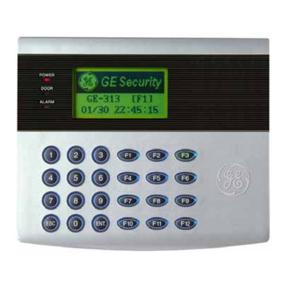
LCD module displays GE313 status. System Operation Status LED: When the power is applied to GE313, the red LED is turned on. When the Relay #1 is operated, the green LED is turned on. When the Relay #2 is operated, the yellow LED is turned on. -
Page 11: Connector Layout
3 .2.2 CONNECTOR LAYOUT Figure: Connector Layout 3 .2.3 WIRE COLOR TABLE OF THE GE313 I /O PORT NAME S IGNAL NAME W IRE COLOR CNN-1: POWER Main Power (+12V) +12V Red wire Power Ground Black wire CNN-2:COMMUNICATION RS485-RTX(+) RS485-A(+) -
Page 12: Installation Tips & Check Point
Door RELAY(COM) COM(1) Green wire with white stripe Door RELAY(NO) NO(1) White wire with red stripe Alarm RELAY(NC) NC(2) Yellow wire with red stripe Alarm RELAY(COM) COM(2) Brown wire with white stripe Alarm RELAY(NO) NO(2) Blue wire with white stripe Exit Button EXIT Orange wire... -
Page 13: Cable Selection Table
Reference Description Cable Specification Maximum Distance GE313 Power (DC12V) Belden #9409, 18 AWG ① DC Power -> GE313 2 conductor, unshielded Belden #9512, 22 AWG Reader (Power and Data) 4 conductor, shielded ② Exit Reader -> GE616 Belden #9514, 22 AWG... -
Page 14: How To Connect Termination Resistor
(GND of GE313) Note that if the chassis ground is not properly connected to the earth and floated from the ground level, then grounding to the chassis ground will give the worst communication;... -
Page 15: Reverse Diode Connection
4 .2.4 REVERSE DIODE CONNECTION If you connect an inductor (Door Locks or Alarm device) to the output relays, there will be a high surge voltage created while the inductor is turning on and off. If you do not connect reverse diode, the surge voltage will transfer and damage to the electronic circuit of the controller. -
Page 16: Backup Battery Switch
After the all installation and connections are completed, press and hold the Initialize button and put the power (+12V DC) to GE313. The LCD will first display “Initialize OK? 0:No 1:Yes”. Press <1> key if you want to initialize the system. After all Initialization process is completed, the system is operating on normal mode and... -
Page 17: Wall Mount Installation
5 .4 WALL MOUNT INSTALLATION Position the Wall Mount to the location where you install the unit and mark 4 x drilling position. Drill 6- 32 holes at least 4 mounting point. Drill 1/2” hole on the center of Wall Mount. Using 4 screws, install the Wall Mount to the proper location. -
Page 18: Output Connection
6 .3 OUTPUT CONNECTION Door Lock (Power Fail Safe) Connection (Door Relay) 1. Connect COM wire of Door Relay, the Green wire with white stripe to +12V. 2. Connect NC wire of Door Relay, the Gray wire with white stripe to (+) wire of door lock device. 3. -
Page 19: Rs232 Port Connection
Figure: External Reader Connection 6 .5 RS232 PORT CONNECTIN A 9-pin connector (Serial communication connector, female) is required to connect the GE313 to a host computer via RS232 communication. Please follow the instructions. 1. Connect RS232-TX, Red wire with white stripe to the pin #2(RXD) of the 9-pin connector. -
Page 20: Rs485 Port Connection
RS485/RS232 converter is required to use RS485 communication between multiple GE313 and a host PC. Please follow the instructions. First, you have to connect all RS485 port of GE313 in parallel. (max. 32 x GE313 Units) 1. Connect RS485-RTX(+), Grey wire of one GE313 to RS485-RTX(+), Grey wire of another GE313. -
Page 21: Tcp/Ip Connection (Optional)
1. Connect RJ45 plug, LAN cable of the network system to RJ45 jack of the GE313. 2. If you install multiple GE313 and only one TCP/IP port is available, you may connect one GE313 to TCP/IP then connect all GE313 units to RS485 multiple communication shown above. -
Page 22: Basic Settings
7 .2 HOW TO ENTER THE SETUP MENU To setup or to change the GE313 settings, you have to enter the SETUP MENU first. To do so, press <0> key eight times (Default Master ID ‘00000000’) and <ENT> key from the Keypad. You now entered to the SETUP MENU. -
Page 23: Language Setting
Second / Day (Total 15 digits) as shown below. The LCD will display the new Date and Time after the time setting is completed but the year and day will not be displayed. GE313 has a 24 hours system and day codes are 1 for Sunday, 2 for Monday, 3 for Tuesday, 4 for Wednesday, 5 for Thursday, 6 for Friday and 7 for Saturday. -
Page 24: Id Registration
7 .5 ID REGISTRATION You can register the User ID into the GE313. Select [F4 SETUP MENU] -> [REGISTRATION] and follow the steps below. 1. Registration by Card 2. Registration by Key 1. Scanning… The reader is waiting for the ID number to be registered. The card number will appear with a beep sound when you present the card. - Page 25 Reader#2 (Exit Reader). If you put ‘1’ for RD (Only Reader#1 assigned) and try to exit through Reader#2 (Exit Reader) then GE313 generates an error message (“Access Door Error”) on the LCD display. 7. MA: MA is the Reader#1 (Built-in Reader) Operating Mode for the cardholder. If you put ‘1’ for MA, Reader#1 is always operating on RF Only Mode.
-
Page 26: Operation
8 .1 NORMAL OPERATION Power on When the power is applied to GE313, the Red LED is turned on. Registered card reading When a registered card (or PIN) is read, the Door (Relay#1) will open for 3 seconds (Default) with the Green LED on. -
Page 27: Setting Changes
SETTING CHANGES ☞. To setup or to change the GE313 settings, you have to enter the SETUP MENU first. To do so, press <0> key eight times (Default Master ID ‘00000000’) and <ENT> key from the Keypad. You now entered to the SETUP MENU. -
Page 28: F1 Setup Menu
9.1 F1 SETUP MENU 9.1.1 VERSION CHECK ☞. The Firmware Version of the GE313 displays on the LCD. Press <4> or <6> key to have a look for other menus on [ F1 SETUP MENU]... - Page 29 9.1.2 INPUT TEST . The 5digit shows the input status and “0” indicates that the input port is open circuit and “1” indicates that the ☞ input port is short circuit to ground level. 9.1.3 OUTPUT TEST ☞. The first two tests are for the output relays (Door Relay and Alarm Relay) test. You can hear the mechanical sound of relays and LED will blink.
- Page 30 9.1.5 KEYPAD TEST ☞. LCD will display all keys of the unit. Press each key from the keypad one by one, the depressed key will disappear from the LCD. Note that ENT key is “#” and ESC key is “*” on the LCD. 9.1.6 READER TEST ☞.
- Page 31 ☞ Before this communication test, connect RS232-RX and RS232-TX wires together. ☞ This test is a loop test and GE313 sends a character to RS232-TX and check whether the RS232-RX receive the same character or not. If you have an error, contact manufacturer for technical support.
-
Page 32: F2 Setup Menu
9.2 F2 SETUP MENU... - Page 33 9.2.1 LANGUAGE ☞. The default Language is in ENGLISH. ☞. There are 6 languages can be selected. (KOREAN, ENGLISH, CHINESE, JAPANESE, SPANISH, PORTUGUESE) 9.2.2 DATE AND TIME SETTING ☞. Example: 200302101330152 => Feb. 10, 2003, 13:30:15, Monday 9.2.3 READER#1 MODE Note: READER#1 is built-in proximity reader in the unit.
- Page 34 9.2.4 READER#2 MODE READER#2 MODE setting is the same as 9.2.3 READER#1 MODE setting. Note: READER#2 is an external Exit reader of the unit. ID(PIN) ONLY: The door is accessible by just presenting the proximity card(or Press the ID Number). ID+P/W: The door is accessible by presenting a card and Password.
- Page 35 9.2.8 BAUD RATE SETTING ☞. GE313 supports 9600, 19200, 38400 and 57600bps of Baud Rate and default Baud Rate is 9600bps. Wrong Baud Rate setting will cause communication error and you have to set same Baud Rate for the same communication network.
-
Page 36: F3 Setup Menu
9 .3 F3 SETUP MENU... - Page 37 GE313 generates an error message and keeps all events stored in the memory. When you select UNUSE, GE313 will not generate an error and new event overwrite into the event buffers. If you use GE313 for standalone (just for door access), select UNUSE.
- Page 38 9.3.3 TIME UNIT SETTING ☞ This menu is to define time unit for 5 output ports. 1sec: Output Time will be calculated by one second time unit for in/out definition. 0.1sec: Output Time will be calculated by 1/10 second time unit (100ms) for in/out definition Ex) If you want to activate Door Relay (Relay #1, DR) for 3 second, you have to set as follow.
- Page 39 ☞. The Anti-pass Back mode is only used when you installed Exit Reader. Do not set this mode in USE when you installed Exit Button. You must install GE313 for entry and Exit Reader for Exit. UNUSE: Anti-pass Back mode OFF USE: Anti-pass Back mode ON ☞.
- Page 40 ☞. This is the function to use GE313 as a Reader and sends 26bit Wiegand Output through two TTL output ports. Press <ENT> key and select USE by pressing <4> or <6> key then press <ENT> key for setting. UNUSE: Normal TTL outputs will be activated.
-
Page 41: F4 Setup Menu
9.4 F4 SETUP MENU 9.4.1 ID REGISTRATION 1. Registration by RF Card... - Page 42 Reader and Exit Reader), code ‘1’ only assigns Reader#1 (Built-in Reader) and code ‘2’ only assigns Reader#2 (Exit Reader). If you put ‘1’ for RD (Only Reader#1 assigned) and try to exit through Reader#2 (Exit Reader) then GE313 generates an error message (“Access Door Error”) on the LCD display.
- Page 43 7. MA: MA is the Reader#1 (Built-in Reader) Operating Mode for the cardholder. If you put ‘1’ for MA, Reader#1 is always operating on RF Only Mode. ‘0’ – System Operating Mode [F2 SETUP MENU] [READER#1 MODE] ‘1’ – ID Only Mode ‘2’...
- Page 44 9.4.3 ID LIST . LCD will display 5digit ID Index, 8digit I D number, 4digit Password, T/S for Reader#1(TA) and ☞ Reader#2(TB), accessible Readers(RD), operating mode for Reader#1(MA) and Reader#2(MB), the output level(LV). ☞ “EMPTY” message will be displayed if there is no registered user ID. ☞...
- Page 45 9.4.5 ID COUNT ☞. This menu displays the total number of registered user ID. It automatically counts when you register or delete user IDs. The LCD shows total 123 user IDs registered in the memory. 9.4.6 EVENT COUNT ☞. This menu displays the total number of Event stored in the memory. It automatically increases the count when the Event is stored in the memory.
-
Page 46: F5 Setup Menu
9.5 F5 SETUP MENU 9.5.1 TIME SCHEDULE... - Page 47 ☞. There are 10 Time Schedule Code available for the users. T/S Code “00” is a default and allows the access for all users for all the time. (Access is granted 24 hours per day) The user can program the Time Schedule Code from “01”...
- Page 48 9.5.3 HOLIDAY CODE ☞. Holiday Code is to link the Holiday Schedule to the Time Schedule. T/S has 5 Time Intervals for holidays and this Time Intervals are only applied to the dates of this Holiday Schedule. Default Holiday Schedule Code is ‘00’...
-
Page 49: F6 Setup Menu
9.6 F6 SETUP MENU... - Page 50 * Default Output Setting for Input Sources Door Alarm TTL#1 TTL#2 Buzzer OUTPUT Relay Relay (T1) (T2) (BZ) (DR) (AR) [1] EXIT BUTTON [2] DOOR CONTACT [3] AUX Input #1 [4] AUX Input #2 [5] TAMPER ALARM [6] DURESS ALARM [7] OUTPUT TIME SCHEDULE [8] INPUT TIME SCHEDULE [9] INPUT TYPE...
- Page 51 9.6.7 OUTPUT TIME SCHEDULE SETTING . You can link a T/S Code to each Output. The default T/S Code is “00” which means no T/S is applied to the ☞ Outputs. This setting is very useful when you want to open the door for a Time Interval. Press <ENT>...
-
Page 52: F7 Setup Menu
9.7 F7 SETUP MENU... - Page 53 * Default Output Setting for Input Circumstance Door Alarm TTL#1 TTL#2 Buzzer OUTPUT Relay Relay (T1) (T2) (BZ) (DR) (AR) [1] Reader#1 ID OK LV1 [2] Reader#1 ID OK LV2 [3] Reader#1 ID OK LV3 [4] Reader#1 ID OK LV4 [5] Reader#1 ID Error [6] Reader#1 T/S Error [7] Reader#1 APB Error...
- Page 54 9.7.2 OUTPUT SETTING FOR READER#1 ID OK LEVEL 2 This Output Time is applied for the users registered with Level#2 output. 9.7.3 OUTPUT SETTING FOR READER#1 ID OK LEVEL 3 This Output Time is applied for the users registered with Level#3 output. 9.7.4 OUTPUT SETTING FOR READER#1 ID OK LEVEL 4 This Output Time is applied for the users registered with Level#4 output.
-
Page 55: F8 Setup Menu
9.8 F8 SETUP MENU 9.8.1 SYSTEM INITIALIZE ☞. This operation will initialize the GE313. Press <ENT> key, if an initialization is needed (First time installation or resetting in the event of a malfunction). CAUTION: Initializing will erase all stored data in the memory. - Page 56 9.8.2 EVENT CLEAR ☞. When the event memory is full or when you want to change ID COUNT, you can clear the event memory in this menu. Press <ENT> key then press <1> key to clear event memory or <0> key to cancel the operation. CAUTION: Before you clear the events, make sure that the stored events is not necessary to upload to the host PC otherwise you may lose important data.
- Page 57 9.8.5 TIME SCHEDULE CLEAR ☞. When you want to delete all Time Schedules (01~10), all Holiday schedules(01~10), Holiday code, Reader#1 Mode T/S code and Reader#1 Mode T/S code, you can clear them from the memory. Press <ENT> key and press the <1> key to clear all T/S or <0> key to cancel the operation. CAUTION: Before you clear all T/S, make sure that the stored T/S is no longer used, otherwise you may lose all stored T/S in the memory.
-
Page 58: Appendix
APPENDIX A. THE RELATION BETWEEN INPUT AND OUTPUT (DEFAULT) * Default Output Setting for Input Sources Door Alarm OUTPUT TTL#1 TTL#2 Buzzer Relay Relay INPUT (T1) (T2) (BZ) (DR) (AR) [1] EXIT BUTTON [2] DOOR CONTACT [3] AUX Input #1 [4] AUX Input #2 [5] TAMPER ALARM [6] DURESS ALARM... - Page 59 * Default Output Setting for Input Circumstance Door Alarm OUTPUT TTL#1 TTL#2 Buzzer Relay Relay INPUT (T1) (T2) (BZ) (DR) (AR) [1] Reader#1 ID OK LV1 [2] Reader#1 ID OK LV2 [3] Reader#1 ID OK LV3 [4] Reader#1 ID OK LV4 [5] Reader#1 ID Error [6] Reader#1 T/S Error [7] Reader#1 APB Error...
-
Page 60: Trouble Shooting
1. The card ID might be registered only to the controller and not registered in the PC. During the process of downloading IDs, GE313 first erase the ID memory of the unit, therefore if the IDs from the PC didn’t contain the card ID, this can happen. - Page 61 01 up to 10 and if the present time is included in the schedule. If it is set to unintended value, change it to “00” ( Programmable via PC software) 4. Check in Tamper switch of GE313. 5. If the trouble remains after checking the above, contact a designated service center.
- Page 62 ☞ “SCHEDULE ERROR” message shows when RFID card is read. Cause Error in RFID card registration, time schedule setting or the system itself. Solution 1. If it was a properly operating unit before, there has been an electric shock that damaged the internal memory and data.
- Page 63 - The parameters at the S/W should be set as following: Parity bit : NONE Data bit : 8bit Stop bit : 1bit 2. Check the line connection for communication. RS232 RS485 (mono) RS485/232 GE313 GE313 Converter The RS232 cable from RTX(-) RTX(-) the converter RTX(+) RTX(+) RS485(Multi Drop) RS485/232...
-
Page 64: Fcc Registration Information
FCC REGISTRATION INFORMATION FCC REQUIREMENTS PART 15 Caution: Any changes or modifications in construction of this device which are not expressly approved by the manufacturer for compliance could void the user's authority to operate the equipment. NOTE: This device complies with Part 15 of the FCC Rules. Operation is subject to the following two conditions;... -
Page 65: Warranty And Service
WARRANTY AND SERVICE GE313 warranty is 1 years from the shipping date; returns must have an RMA (Return Material Authorization) number. The customer is to provide a description of the specific problem. The customer is to include serial numbers, formats, and model numbers with the items to be returned. -
Page 66: Rma Request Form & A/S Request Form
RMA REQUEST FORM & A/S REQUEST FORM RMA REQUEST FORM : ORIGINAL ID TECK Co., LTd 5F, Ace Techno Tower B/D, 684-1, Deungchon Dong, Gangsuh Gu, Seoul, Korea 157-030 TEL : +82-2-2659-0055, FAX ; +82-2-2659-0086, www.idteck.com RMA REQUEST FORM Send To RMA No. & Date : RMA Control Center Original Invoice No. - Page 67 RMA REQUEST FORM : SAMPLE ID TECK Co., LTd 5F, Ace Techno Tower B/D, 684-1, Deungchon Dong, Gangsuh Gu, Seoul, Korea 157-030 TEL : +82-2-2659-0055, FAX ; +82-2-2659-0086, www.idteck.com RMA REQUEST FORM Send To RMA No. & Date : We send this No. , when you want.
- Page 68 A/S REQUEST FORM : ORIGINAL...
- Page 69 A/S REQUEST FORM : SAMPLE...
- Page 70 MEMO...
- Page 71 The specification contained in this manual are subject to change without notice at any time. 5F, Ace Techno Tower B/D, 684-1, Deungchon-Dong, Gangsuh-Gu, Seoul, Korea 157-030 Tel : (82) 2 2659-0055 Fax : (82) 2 2659-0086 E-mail : webmaster@idteck.com MAR. 2005 Copyright ©2004 IDTECK Co., Ltd.
Need help?
Do you have a question about the GE313 and is the answer not in the manual?
Questions and answers