Table of Contents
Advertisement
Quick Links
Owner's Manual
Console KVM Switch
with IP Access
Model: B030-008-17-IP
PROTECT YOUR INVESTMENT!
Register your product for quicker service and ultimate peace of mind.
You could also win an ISOBAR6ULTRA surge protector—a $100 value!
www.tripplite.com/warranty
1111 W. 35th Street, Chicago, IL 60609 USA • www.tripplite.com/support
Copyright © 2016 Tripp Lite. All rights reserved.
1
Advertisement
Table of Contents

Related Manuals for Tripp Lite B030-008-17-IP


Summary of Contents for Tripp Lite B030-008-17-IP
- Page 1 Register your product for quicker service and ultimate peace of mind. You could also win an ISOBAR6ULTRA surge protector—a $100 value! www.tripplite.com/warranty 1111 W. 35th Street, Chicago, IL 60609 USA • www.tripplite.com/support Copyright © 2016 Tripp Lite. All rights reserved.
-
Page 2: Table Of Contents
Table of Contents 1. FCC Information ............. 4 11. KVM Web Interface ............32 11.1 Web Interface Main Page ........32 2. User Notice ..............4 11.1.1 Tab Bar ............ 33 3. Package Contents ............4 11.2 Port Access ............33 4. - Page 3 Table of Contents 16. Maintenance ..............80 19. Auto Scan Mode ............100 16.1 Upgrade Main Firmware ........80 19.1 Setting the Scan Interval ........100 16.1.1 Main Firmware Upgrade Recovery ....80 19.2 Initiating Auto Scan ........... 100 16.2 Update Display Info ..........81 19.3 Pausing Auto Scan ..........
-
Page 4: Fcc Information
The user must use shielded cables and connectors with this equipment. Any changes or modifications to this equipment not expressly approved by Tripp Lite could void the user’s authority to operate this equipment. -
Page 5: Features
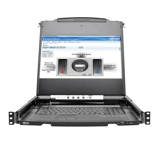
4. Features • Console HDMI KVM Switch with built-in IP Access in a dual-rail housing with top and bottom clearance for integrated operation in 1U of rack space. • KVM console combines a 17.3” LCD monitor, keyboard, and touchpad. • Connect an External DVI monitor or computer using HDMI to DVI adapter cables. •... -
Page 6: System Requirements
5. System Requirements 5.1 Built-in LCD Console The integrated LCD monitor’s maximum resolution is 1920 x 1080 @60 Hz. Ensure all resolution settings of the connected computers do not exceed the LCD monitor’s maximum resolution. 5.2 Optional External Console • A DVI (adapter required) or HDMI monitor capable of displaying the highest resolution provided by any computer in the installation. •... -
Page 7: Rear View
5. System Requirements Component Description Handle Pull to slide the KVM module out; push to slide it in. LCD Module After sliding out the KVM module, flip up the cover to access the LCD monitor. LCD Controls The buttons to control the position and picture settings of the LCD monitor are located here. LCD On / Off Button Push this button to turn the LCD monitor on and off. -
Page 8: Important Safety Instructions
• Consideration should be given to the connection of equipment and the supply circuit, as well as what effect overloading the supply circuit might have on overcurrent protection and supply wiring. • To help protect the system from unexpected transient increases and decreases in electrical power, use a Tripp Lite Surge Protector, Line Conditioner, or Uninterruptible Power Supply (UPS). -
Page 9: Rack Mounting Safety Instructions
6. Important Safety Instructions 6.2 Rack Mounting Safety Instructions • The ambient operating temperature in the rack may be an issue and is dependent upon the rack load and ventilation. When installing in a closed or multi-device rack assembly, ensure the temperature will not exceed the maximum rated ambient temperature. •... -
Page 10: Installation
7. Installation The B030-008-17-IP is designed for mounting in a 1U rack system. For convenience, a rack mounting kit is included for quick installation. The various mounting options are explained in the following subsections. 7.1 Standard Rack Mounting The standard rack mounting brackets that come attached to the console KVM switch allow the device to be installed in a standard 1U rack by a single individual. -
Page 11: Opening/Closing The Console
Connect the LAN port on the back of the device to the network using Cat5e/6 cable. Plug the included power cord into a Tripp Lite Surge Protector, Power Distribution Device (PDU), Uninterruptible Power Supply (UPS) or AC wall outlet. -
Page 12: Opening Together
7. Installation 3. Rotate the top panel all the way back to expose the LCD screen. 4. Reach underneath and pull out the keyboard module until it clicks into place. 7.5.2 Opening Together Refer to the diagrams in the Opening Separately section as you do the following: 1. -
Page 13: Opening Precautions
7. Installation 7.5.3 Opening Precautions The maximum load bearing capacity of the keyboard module is 65 lb. Failure to heed the instructions below can result in damage to the keyboard module. CORRECT Rest your hands and arms lightly on the keyboard module as you work. INCORRECT! •... -
Page 14: Closing The Console
7. Installation 7.5.4 Closing the Console 1. Engage the release catches located on either side of the keyboard to release the keyboard module, then slide in the module slightly. 2. Release the catches. Using the front handle, push the keyboard module all the way in. - Page 15 7. Installation 3. Rotate the LCD module all the way down, then engage the rear catches to release the LCD module. 4. Using the front handle, push the module all the way in.
-
Page 16: Network Setup - Ip Address Configuration
7. Installation 7.6 Network Setup – IP Address Configuration By default, the KVM will automatically have an IP address assigned via DHCP server. To configure a fixed IP address, you will need to access the KVM switch in one of three ways: Local Console, IP Installer or Browser. 7.6.1 Local Console Note: The local console OSD only allows IPv4 network settings configuration. -
Page 17: Ip Installer
7. Installation 7.6.2 IP Installer Computers running Windows can use the IP Installer utility found in the included CD-ROM to assign an IP address to the KVM. Notes: • The IP Installer Settings section located in the KVM’s Web Management Interface network page must be enabled in order to use the IP Installer to assign an IP address. - Page 18 7. Installation 3. If accessing the KVM for the first time, enter the username administrator and the password password. For security purposes, changing the username and password is strongly recommended. Once the default username and password are entered, the web management interface will appear with the following page displayed: 4.
-
Page 19: Basic Operation
Note: The Language setting does not return to the factory default, but remains at the one it is currently set to. 8.1.3 Hot Plugging The B030-008-17-IP supports hot plugging – components can be removed and added to the computer by unplugging their cables from the ports without the need to shut down the KVM. -
Page 20: Kvm Operation
9. KVM Operation 9.1 Local Console 9.1.1 Local Console Login When accessing the console KVM switch for the first time, a prompt will appear asking for a username and password. The default username is administrator, and the default password is password. For security purposes, changing the username and password on this account is strongly recommended. -
Page 21: Osd Navigation
9. KVM Operation 9.1.4 OSD Navigation • To dismiss the menu and deactivate the OSD, click the X in the upper right corner of the OSD window or press [Esc]. • To log out, click the ZZZ icon in the upper right corner of the main screen or press [F8]. •... - Page 22 9. KVM Operation F3: Set This function allows the administrator and users to set up their own working environments. A separate profile for each client is stored by the OSD and activated according to the username provided during login. To change a setting: 1.
- Page 23 9. KVM Operation F4: ADM F4 is an administrator-only function. It allows the administrator to configure and control the overall operation of the OSD. To change a setting, double-click or move the highlight bar to its location, then press [Enter]. After selecting an item, a submenu with additional choices will appear.
- Page 24 9. KVM Operation Set IP Address The KVM can have an IP address assigned dynamically (DHCP) or be given a fixed IP address. • Obtain an IP address automatically (DHCP) – This option is selected by default. If the Use the following IP address option is selected instead, check the radio button next to the Obtain an IP address automatically (DHCP) option to switch.
- Page 25 9. KVM Operation Reset Default Values Clicking this button undoes all Customization page changes that have been made to the B030-008-17-IP and returns the parameters to the original factory default settings. The reset values include the following items: • Security –...
- Page 26 9. KVM Operation Ctrl + E: Edit Favorites To add a Favorites list: 1. Enter the new Favorites list name in the Name highlight bar. 2. Click Add to add a list in the left menu box. 3. To add a port, move the highlight bar to choose a Favorite list and press [Enter] or [Space], or double-click on a port to select. Click the Update option to save changes or highlight using up/down keys and press [Enter].
- Page 27 9. KVM Operation Port OS Specifies the operating system the server on the connected port is using. Choices are Win, Mac, Sun, and Other. The default is Win. OS Language Specifies the OS language used by the server on the connected port. Use the drop down list to view the available choices. The default is US English.
-
Page 28: Logging In To The Kvm Over Ip
10.1 Web Browser The B030-008-17-IP can be accessed via an internet browser running on any platform. To access the device: 1. Open the browser and specify the IP address of the switch to access in the browser’s URL bar. - Page 29 10. Logging In to the KVM over IP 5. Upon entering the serial number, the AP Windows Client main screen will appear. 6. The AP Windows Client will search the network for any KVM switches and display their Model Name(s) and IP Address(es) in the main screen’s Server List.
- Page 30 Work files. The Help Menu displays the AP Windows Client version number. Server List Each time the WinClient.exe file is run, it searches the User’s LAN segment for B030-008-17-IP KVM Switches and lists in the box any that are found. Double-click on any of the devices in this list to connect.
-
Page 31: Ap Java Client Login
10. Logging In to the KVM over IP 10.3 AP Java Client Login In cases when an Administrator does not want the KVM Switch to be available via browser and the remote user is not running Windows, the AP Java Client provides access to the KVM switch. After downloading the AP Java Client, double-click on the program download location on your hard disk to show the connection screen. -
Page 32: Kvm Web Interface
11. KVM Web Interface 11.1 Web Interface Main Page When logging into the KVM switch, the following page displays: Tab Bar The Tab Bar consists of category icons that direct to various interfaces used to operate the KVM switch. The icons displayed in the Tab Bar depend on the user type and permissions. Menu Bar The Menu Bar consists of subcategories that display, depending on the user type and permissions. -
Page 33: Tab Bar
There are two small icons in the upper right-hand corner of the page. Their functions are: Icon Function Initiates a panel with information about the B030-008-17-IP firmware version. Log outs and ends the B030-008-17-IP session. 11.2 Port Access The Port Access section in the OSD is where users can access KVM ports and control settings affecting that access. - Page 34 11. KVM Web Interface When accessing a port for the first time via web browser, users will experience a series of prompts: Internet Explorer When logging onto the KVM switch via Internet Explorer, the default viewer is the Windows ActiveX viewer. To use the Java Viewer when accessing the KVM switch via Internet Explorer, the Viewer setting in the User Preferences page must first be updated.
-
Page 35: Port Selection List
Do this automatically for files like this from now on box. 2. A prompt to run the Java Viewer will appear. Check the Always trust content from this publisher (Tripp Lite) box, then click Run. 11.2.2 Port Selection List •... -
Page 36: Web Interface Icons And Controls
11. KVM Web Interface 11.3 Web Interface Icons and Controls Panel Array Mode Panel Array Mode permits port activity to be monitored automatically. When activated, the screen displays a grid of panels, with each panel representing a port on the installation. Only ports that are online and user accessible are displayed. Offline or non-accessible ports are left blank. -
Page 37: Port Level
11. KVM Web Interface 11.4.2 Port Level When a port is selected in the Sidebar tree, the port connection and configuration options will appear. Section Description Status Displays the Port Status; whether it is online or offline, and whether virtual media can be mounted to it. Click the Connect button to open a remote session with the selected port displayed. -
Page 38: Favorites
11. KVM Web Interface 11.6 Favorites Favorites is similar to a bookmarks feature, where frequently visited ports can be listed on this page. Open this page and select the port instead of searching for it in the tree view. Note: Each Favorites bookmark created is a unique folder in which multiple ports can be saved. Adding a Favorite To add a port to Favorites: 1. - Page 39 11. KVM Web Interface 4. Repeat step 3 for any additional ports to add to the Favorites bookmark. Modifying a Favorite To modify a Favorites bookmark, right-click on it and select one of the options from the pop-up menu that appears. To edit a Favorite’s name, click on it once, wait a second, then click again.
-
Page 40: User Preferences
11. KVM Web Interface 11.7 User Preferences The User Preferences page allows users to set up their own individual working environments. The KVM Switch stores a separate record for each user profile, and sets up the working environment according to the Username that was used to access the KVM switch. Setting Description Language... -
Page 41: Sessions
11. KVM Web Interface 11.8 Sessions The Sessions subsection allows Super Administrators and Administrators to view users logged in to the KVM switch, and provides information about each session. Super Administrators can view all user accounts logged in to the KVM, whereas Administrators are only able to view Administrator and User accounts. -
Page 42: Port Configuration
11. KVM Web Interface If a port is chosen in the Sidebar, the Main panel consists of three columns: Name, Access and Config: • Name lists all users that have been created. • The Access column is where device access rights are set. To cycle through the choices, click the icon in the row that corresponds to the user to be configured. - Page 43 11. KVM Web Interface When a standard port is highlighted and the Port Configuration subsection is selected, a screen opens up containing two sections; Port Property and Associated Link. The Port Property section is opened first by default. Field Explanation Port OS Specifies the operating system the server on the connected port is using.
-
Page 44: Associated Link
11. KVM Web Interface 11.11 Associated Link This page associates links to other ports in the installation with the highlighted port. When an associated link is made, it is displayed in the Associated Link table of the port’s Connections screen. To add an associated link, click the Add button, enter the desired port number in the box that appears, and click the OK button. - Page 45 11. KVM Web Interface Adding User Accounts To add a new user account: 1. Highlight Users from the list on the left side of the page, then click the Add button located at the bottom of the screen. The user information page will open.
- Page 46 11. KVM Web Interface Permissions The permission settings determine what functionality the account is able to use. Check the box next to the permission to enable it to that account. Leave it unchecked to deny the account access to that functionality. Note: For ordinary •...
-
Page 47: Device Assignment
11. KVM Web Interface 11.12.1 Device Assignment When a user logs on to the KVM switch, the ports they are allowed to access are displayed in the port list. Ports they are not allowed to access are not displayed. Port access rights, as well as access to configuration settings, are assigned on a port-by-port basis in the user Device tab. To access the Device tab, first access the user information page, then click on the Device tab at the top of the page. -
Page 48: Device Information
11. KVM Web Interface 11.12.3 Device Information When the Device Management icon is selected, it opens with the Device Information page displayed. Note: If you do not have permission to configure the KVM switch, the Device Management icon will not appear when you log onto the KVM. The General Device Information page displays the name of the selected device, its firmware version, the FPGA (Field-Programmable-Gate-Array) and information about its network configuration. -
Page 49: Operating Mode
The Operating Mode subsection allows the working parameters of the KVM to be set. • If Force all to grayscale is enabled, the remote displays of all devices connected to the B030-008-17-IP are changed to grayscale. This can speed up I/O transfer in low bandwidth situations. -
Page 50: Network Settings
12. Network Settings... - Page 51 Description IP Installer The B030-008-17-IP includes an IP Installer application that allows Windows computers to easily view and edit the KVM’s network settings. This section determines what access the IP Installer has to the KVM switch. • Enabled – When selected, the IP Installer can locate the KVM switch on the network and display its current IP address. It also allows the IP Installer to be used to change the KVM’s IP address.
-
Page 52: Advanced Network Management Settings (Anms)
12. Network Settings 12.1 Advanced Network Management Settings (ANMS) The Advance Network management Settings (ANMS) are used to set up login authentication and authorization management from external sources. It is split up into two pages; Event Destination and Authentication. Event Destination The Event Destination page allows the KVM to be set up to record and send notifications of events that take place on the system. - Page 53 12. Network Settings Log Server In addition to the OSD’s built-in log, the KVM includes an external Windows-based log server that can be installed on a computer (refer to 17. Log Server for details). The Log Server section on this page explains where the external log server can be enabled and set up for use. To do this, follow the steps below.
-
Page 54: Radius Settings
5. In the Shared Secret field, key in the character string to use for authentication between the KVM Switch and the RADIUS Server. 6. On the RADIUS server, Users can be authenticated with the following methods: – Set the entry for the user as su/xxxx, where xxxx represents the Username given when the account was created in the B030-008-17-IP User Management page. - Page 55 12. Network Settings Win2K3 IP: 10.8.8.30 1. Start the Microsoft Management Console (MMC) and add the Internet Authentication Service by choosing Add/Remove Snap-in from the console menu. Click Add and select the IAS Snap-in. Choose the Local Computer. Or go to: Start > Programs > Administrative Tools > Internet Authentication Service.
- Page 56 12. Network Settings 2. Create a rule to allow the Access Gateway access to the RADIUS server. Note: The Shared Secret is the same one used when configuring the B030-008-17-IP .
- Page 57 12. Network Settings 3. Create a New Remote Access Policy and click Next.
- Page 58 12. Network Settings...
- Page 59 12. Network Settings 4. Create an Access Control List Policy (one policy per user).
- Page 60 12. Network Settings Note: kvmadmin is a user created in Win2K3 in advance.
- Page 61 Click Configure Attribute. In the screen that appears, set the entry for the user as su/xxxx, where xxxx represents the Username given when the account was created in the B030-008-17-IP User Management page. User access rights will be the same as those assigned to the KVM switch (refer to 11.12 User Management for more information).
-
Page 62: Ldap / Ldaps Authentication And
12. Network Settings 12.2 LDAP / LDAPS Authentication and Authorization Settings To allow authentication and authorization for the B030-008-17-IP via LDAP / LDAPS: Item Description Enable Check the Enable box to allow LDAP / LDAPS authentication and authorization. LDAP / LDAPS Click to specify whether to use LDAP or LDAPS. -
Page 63: Extend And Update The
12. Network Settings Creating a Start Menu Shortcut Entry 1. Right click Start; select: Open all Users Programs Administrative Tools. 2. On the File menu, select New Shortcut 3. In the dialog box that appears, browse to or enter in the path to schmmgmt.msc (C:\Windows\system32\schmmgmt.msc) and click Next. 4. -
Page 64: Active Directory Schema
12. Network Settings e) Fill in the dialog box according to the example below and click OK. • Common Name – userprofile • LDAP Display Name – userprofile • Syntax – Unicode String • Minimum – 1 • Maximum – 255 Note: The Unique X500 Object ID uses periods, not commas. - Page 65 12. Network Settings d) Select Properties; the user’s Properties page will appear with the General tab displayed. e) Select the Attributes tab and click Add:...
- Page 66 12. Network Settings f) In the list that appears, select userprofile, then click OK. Step 3 - Edit Active Directory Users with the Extended Schema: a) Run ADSI Edit (installed as part of Support Tools.) b) Open Domain and navigate to the cn=users dc=tripplite dc=com node. c) Locate the user you wish to edit.
- Page 67 12. Network Settings d) Right-click on the user’s name and select Properties. e) On the Attribute Editor page of the dialog box that appears, select userprofile from the list. f) Click Edit to access the String Attribute Editor: g) Replace the value shown with su/xxxx, where xxxx represents the username assigned to the user in the KVM switch. User access rights will be the same as those assigned to them in the KVM switch (refer to 12.1 User Management for details).
-
Page 68: Openldap Server Installation
12. Network Settings i) Click Apply to save the change and complete the procedure. j) Repeat Step 3 (Edit Active Directory Users with the Extended Schema) to add any additional users. 12.3 OpenLDAP Server Installation OpenLDAP is an open source LDAP server designed for UNIX platforms. A Windows version can be downloaded from: http://download.bergmans.us/openldap/openldap-2.2.29/openldap-2.2.29-db-4.3.29-openssl-0.9.8awin32_Setup.exe. -
Page 69: Starting The Openldap Server
12. Network Settings An example configuration file will appear as: 12.3.2 Starting the OpenLDAP Server To start the OpenLDAP Server, run slapd (the OpenLDAP Server executable file) from the command line. slapd supports a number of command line options, the most important option is the d switch that triggers debug information. For example, a command of slapd -d 256 would start OpenLDAP with a debug level of 256, as shown in the following screenshot: Note: For details about slapd options and their meanings, refer to the OpenLDAP documentation. -
Page 70: Customizing The Openldap Schema
The schema that slapd uses may be extended to support additional syntaxes, matching rules, attribute types, and object classes. In the case of the B030-008-17-IP , the User class and the permission attribute are extended to define a new schema. The extended schema file used to authenticate and authorize users logging in to the KVM Switch is shown in the figure below: 12.4 LDAP DIT Design and LDIF File... -
Page 71: Dit Creation
The LDAP Data Interchange Format (LDIF) is used to represent LDAP entries in a simple text format (refer to RFC 2849). The figure below illustrates an LDIF file that creates the DIT for the B030-008-17-IP directory tree (shown in the figure in the previous section). -
Page 72: Using The New Schema
12.4.3 Using the New Schema To use the new schema: 1. Save the new schema file (e.g., B030-008-17-IP .schema) in the /OpenLDAP/schema/ directory. 2. Add the new schema to the slapd.conf file, as shown in the figure below. 3. Restart the LDAP server. -
Page 73: Security
To enable IP and/or MAC filtering, check the IP Filter Enable and/or MAC Filter Enable box. A maximum of 100 filters are allowed for each. • If the Include button is checked, addresses within the filter range are allowed access to the B030-008-17-IP; all other addresses are denied access. -
Page 74: Ip Filtering
13. Security 13.2.1 IP Filtering To add an IP filter: 1. Check the IP Filter Enable box. 2. Click Add. A dialog box will appear: 3. To filter a single IP address, enter the same IP address into the From and To fields. 4. -
Page 75: Mac Filtering
13. Security 13.4 MAC Filtering To add a MAC filter: 1. Click Add. A dialog box appears: 2. Type in the desired MAC address and click OK. 3. Repeat these steps for any additional MAC addresses to filter. To delete a MAC filter: Select the desired MAC filter from the list and click Remove. -
Page 76: Mode
13. Security 13.6 Mode The Mode operation settings are described in the table below. Item Description Enable ICMP When this box is checked, the KVM switch can be pinged. If it is not checked, the KVM cannot be pinged. Enable Multiuser Operation When this box is checked, multiple accounts (up to 32) can remotely log on to the KVM at the same time. If not selected, only one user can log on at a time. -
Page 77: Date/Time
14. Date/Time The Date/Time page sets the date and time parameters for the KVM switch. 14.1 Time Zone • From the drop-down menu at the top of the section, select the Time Zone and City that most closely resembles where the KVM switch is located. -
Page 78: Log
15. Log The B030-008-17-IP logs all the events that occur and records them to a log file. The Log Information page can store up to 512 events, at which time the oldest files are deleted and replaced with newer files. The records it displays show the Time, Severity, User and Log Information associated with the event. - Page 79 15. Log Notification Settings Notification Settings select which events are sent out to SNMP , SMTP and SysLog servers. Simply check the boxes in the rows of the events that you want notifications for and check the column(s) of the methods you want them to be sent to. When checked, the corresponding event notification will be sent using the corresponding method.
-
Page 80: Maintenance
4. Click the Browse button, and navigate to and select the firmware upgrade file downloaded from the Tripp Lite website. When selected, the Upgrade Firmware button becomes active. -
Page 81: Update Display Info
16. Maintenance 16.2 Update Display Info The Update Display Info button queries the local monitor’s EDID information and updates it. The EDID information communicates with the server’s video card about the display hardware it is connected to (e.g. the monitor connected to the KVM console). The monitor’s Preferred Resolution (Optional) is included in the Display Information window. -
Page 82: Ping
3. Select as many options you wish to restore, then click the Restore button. Once complete, a message will appear stating the procedure succeeded. 16.4 Ping The Ping menu item checks the network status of devices on the B030-008-17-IP installation: To ping a device: 1. Enter the device’s IP Address or Host Name into the text entry box. -
Page 83: System Operation
16. Maintenance 16.5 System Operation The System Operation subsection clears port name and resets the KVM configuration settings to their default values. Item Description Clear Port Names Click this button to clear all port names on the installation and restore to their default values. Upon clicking this but- ton, a prompt will appear to confirm that you wish to clear all port names. -
Page 84: Log Server
17. Log Server The Windows-based Log Server is an administrative utility that records all the events on selected B064-Series KVM Switch units and writes them to a searchable database. 17.1 Installation 1. From the computer designated as the Log Server, open the browser and log in to the KVM Switch. 2. -
Page 85: Configure
17. Log Server 17.3.1 Configure The Configure menu consists of three functions: Add, Edit and Delete. Select the Add function when adding a new KVM switch to the list of units the Log Server records events for. Note: First add a KVM via the Add function before the Log Server can start recording its events. When opening the Add function, the following dialog box will appear (function descriptions can be found in the table below): Field Description... -
Page 86: Events
17. Log Server 17.4 Events The Events Menu consists of two items: Search and Maintenance. 17.4.1 Search Search allows users to search for events containing specific words or strings. When accessing this function, a window will open (item descriptions can be found in the table below): Item Description Search Options New search: When selected, the search is performed on all the events in the database for the selected KVM. -
Page 87: Maintenance
17. Log Server 17.5 Maintenance This function allows the administrator to remove all records that have passed their expiration limit (refer to 17.3.1 Configure for limit details). In order to delete old files from the log server, the maintenance function must be performed. 17.6 Options The Options menu consists of only one function: Network Retry. -
Page 88: Log Server Main Screen
17. Log Server 17.8 Log Server Main Screen The Log Server Main Screen is divided into two main panels: an upper (List) panel displaying all devices added to the Log Server and a lower (Event) panel displaying log events for the currently selected KVM. To select a KVM unit in the list, simply click on it. List Panel Fields Field Description... -
Page 89: Remote Session Operation
18. Remote Session Operation After successfully logging in (see 10. Logging in to the KVM over IP for more information), the Web Interface Main Page will appear with the Port Access tab selected: All ports that a user is permitted to access are listed on the left of the Port Selection panel. Ports that users do not have access to will not be displayed. -
Page 90: Control Panel
18. Remote Session Operation 18.1 Control Panel The Control Panel is a way for the user to optimize and control the remote session. Regardless of whether the user initiated a remote session via the Windows or Java browser and non-browser clients, the control panel and its functionality remain the same. To display the Control Panel, hover the mouse pointer over the top-center of the remote screen. - Page 91 18. Remote Session Operation Basic Video Settings Advanced Video Settings Video Adjustment Options Option Usage Move the RGB (Red, Green, Blue) slider bars to adjust the corresponding color component of the video image. Check the Set to Grayscale box to display the video of the remote computer without color. If the remote keyboard and mouse response time is slow or choppy, the Set to Grayscale option can speed it up.
- Page 92 The file type, quality and location can be changed via the Customize Control Panel page. Message Board – The B030-008-17-IP supports multiple user logins, which can cause access conflicts. To alleviate this problem, a message board feature allows users to communicate with one another.
- Page 93 Note: This feature is only available in windowed mode (Full Screen Mode is off). On-Screen Keyboard – The B030-008-17-IP features an on-screen keyboard, available in multiple languages, with all of the standard keyboard keys for each language. Click this icon to display the on-screen keyboard.
- Page 94 18. Remote Session Operation Mouse Pointer – Click to choose how the local and remote mouse pointers are displayed. You can choose to display Dual mouse pointers, Crosshairs mouse pointers, the local mouse pointer as a tiny dot, or only the remote mouse pointer. Dual mouse pointers display both local and remote mice as arrows.
- Page 95 18. Remote Session Operation Windows XP and later: 1. Open the Mouse Properties dialog box 2. Click the Pointer Options tab 3. Set the mouse speed to the middle position (6 devices in from the left) 4. Disable Enhance Pointer Precision Sun / Linux: Open a terminal session and issue the following command: Sun: xset m 1...
- Page 96 18. Remote Session Operation Control Panel Style This section lets a user determine how the control panel is displayed when it is dragged out of the default position in the top-center of the screen. Note: A second default position for the control panel is available at the bottom-center of the screen. •...
-
Page 97: Remote Session Toolbar
18. Remote Session Operation Keyboard Pass Through When selected, the [Alt, Tab] function will be sent to the remote computer. When it is not selected, the [Alt, Tab] function is sent to the local computer. It is deactivated by default. Exit –... -
Page 98: Panel Array Mode
18. Remote Session Operation 18.2.2 Remote Session Toolbar Hotkeys When the Toolbar is displayed, hotkeys can be used to switch between ports. Hotkey Action Skips to the first accessible port before the current port. To control the selected port, press [Esc] or click on the X icon in the Toolbar Skips to the first accessible port after the current port. -
Page 99: Panel Array Toolbar Icons
18. Remote Session Operation 18.3.1 Panel Array Toolbar Icons The Panel Array Toolbar provides shortcut navigation and control of the panel array. Icon Description Click and drag any part of the toolbar that is not an icon to move the toolbar to another position on the screen. Pauses panel scanning so the focus remains on the currently selected panel. -
Page 100: Auto Scan Mode
19. Auto Scan Mode The Auto Scan function automatically switches among all accessible ports at regular intervals so the user can monitor their activity without having to manually switch between ports. The ports accessed in Auto Scan mode can be further filtered via the Filter section of the Port Access page. -
Page 101: Exiting Auto Scan
20. Appendix 20.1 Keyboard Emulation 20.1.1 Mac Keyboard The PC compatible (101/104 key) keyboard can emulate the functions of the Mac keyboard. The emulation mappings are listed in the table below. PC Keyboard Mac Keyboard [Shift] Shift [Ctrl] Ctrl [Ctrl] [1] [Ctrl] [2] [Ctrl] [3] [Ctrl] [4]... -
Page 102: Troubleshooting
20. Appendix 20.2 Troubleshooting 20.2.1 General Operation Problem Action Erratic Operation. If a KVM switch is cascaded from it, the upper-level KVM must always be powered on before the lower-level KVM. If the cascaded switch was turned on first, resetting it may resolve the issue. If not, power off the installation and power everything on according to the installation instructions in this manual. -
Page 103: Administration
20. Appendix 20.2.2 Administration Problem Action After upgrading the firmware and Clear your browser’s cache. Delete all temporary internet files and cookies. Close the browser and logging back in, the KVM appears to reopen it to log in with a new session. still be using the old firmware version. -
Page 104: Winclient Activex Viewer
20. Appendix 20.2.5 WinClient ActiveX Viewer Problem Action The WinClient ActiveX Viewer will not DirectX 8.0 or higher must be installed on your client computer. connect to the KVM switch. After upgrading the firmware to my The old .ocx file version was not deleted. Open Explorer and search for WinClient.ocx. Delete all KVM switch, the WinClient ActiveX occurrences. -
Page 105: Log Server
20. Appendix 20.2.8 Log Server Problem Action The Log Server program does not run. The Log Server requires the Microsoft Jet OLEDB 4.0 driver in order to access the database. This driver is automatically installed with Windows ME, 2000 and XP . For Windows 98 or NT, go to the Microsoft download site: http://www.microsoft.com/data/download.htm to retrieve the driver file: MDAC 2.7 RTM Refresh (2.70.9001.0). -
Page 106: Specifications
20. Appendix 20.3 Specifications Model B030-008-17-IP Port Selection Methods Pushbutton, OSD, Web Interface / Toolbar External Console Ports HDMI (Female), 2 x USB-A (Female) Computer Ports RJ45 LAN Ports Housing Metal, Dual-Rail Power LEDs 1 x Green Online LEDs 8 x Orange... -
Page 107: Warranty And Product Registration
One-Year Limited Warranty TRIPP LITE warrants its products to be free from defects in materials and workmanship for a period of one (1) year from the date of initial purchase. TRIPP LITE’s obligation under this warranty is limited to repairing or replacing (at its sole option) any such defective products. To obtain service under this warranty, you must obtain a Returned Material Authorization (RMA) number from TRIPP LITE or an authorized TRIPP LITE service center.
Need help?
Do you have a question about the B030-008-17-IP and is the answer not in the manual?
Questions and answers