Tripp Lite NetDirector B030-DP08-17D Owner's Manual

Tripp Lite NetDirector B030-DP08-17D Owner's Manual

8/16-port netdirector displayport rack-mount console kvm switch

Advertisement

Owner's Manual
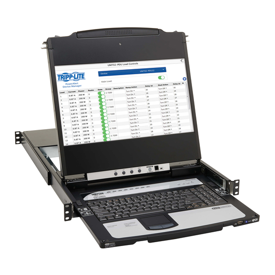
8/16-Port NetDirector
DisplayPort Rack-Mount
Console KVM Switch
Models: B030-DP08-17D / B030-DP16-17D
WARRANTY REGISTRATION
Register your product today and be
automatically entered to win an ISOBAR
surge protector in our monthly drawing!
tripplite.com/warranty
1111 W. 35th Street, Chicago, IL 60609 USA • tripplite.com/support
®
Copyright © 2020 Tripp Lite. All rights reserved.
1
®

Advertisement

Table of Contents
loading

Summary of Contents for Tripp Lite NetDirector B030-DP08-17D

  • Page 1 WARRANTY REGISTRATION Register your product today and be automatically entered to win an ISOBAR ® surge protector in our monthly drawing! tripplite.com/warranty 1111 W. 35th Street, Chicago, IL 60609 USA • tripplite.com/support Copyright © 2020 Tripp Lite. All rights reserved.
  • Page 2: Table Of Contents

    Table of Contents 1. FCC Information 9. KVM Operation 2. User Notice 9.1 Local Console 9.1.1 Local Console Login 3. Package Contents 9.1.2 Local Console OSD 4. System Requirements Hotkey Sequence 4.1 Built-In LCD Console 9.1.3 OSD Main Menu 9.1.3.1 OSD Main Menu 4.2 Optional External Console Headings 4.3 Computers...
  • Page 3: Fcc Information

    The user must use shielded cables and connectors with this equipment. Any changes or modifications to this equipment not expressly approved by Tripp Lite could void the user’s authority to operate this equipment.
  • Page 4: Package Contents

    3. Package Contents • B030-DP08-17D / B030-DP16-17D Console KVM Switch • (x2) DisplayPort Cables – 6 ft. • (x2) USB 2.0 A/B Cables – 6 ft. • (x1) IEC C13 to NEMA 5-15P Power Cord • (x1) Grounding Wire • (x1) Quick Start Guide •...
  • Page 5: System Requirements

    4. System Requirements 4.1 Built-In LCD Console The integrated LCD monitor’s maximum resolution is 1920 x 1080 @ 60 Hz. Ensure all resolution settings of the connected computers do not exceed the LCD monitor’s maximum resolution. 4.2 Optional External Console •...
  • Page 6: Features

    5. Features • DisplayPort Rack-Mount Console KVM Switch in a dual-rail housing with top and bottom clearance for integrated operation in 1U of rack space. • KVM console combines a 17.3” LCD monitor, keyboard and touchpad. • Multi-platform support; compatible with Windows , Mac , Linux and Sun.
  • Page 7 5. Features No. Component Description Handle Pull to slide the LCD module out; push to slide it in. After sliding the LCD module out, flip up the cover to access the LCD LCD Module display. LCD Controls Buttons that control the position and picture settings of the LCD display. Push this button to turn the LCD monitor on and off.
  • Page 8 5. Features Rear View Model B030-DP08-17D Model B030-DP16-17D No. Component Description Standard 3-prong AC power socket. The power cord from an AC source Power Socket plugs in here. Power Switch Standard rocker switch that powers the device on and off. Supports an independent, external KVM console for flexibility and External Console Section convenience.
  • Page 9: Important Safety Instructions

    • Consideration should be given to the connection of equipment and the supply circuit, as well as what effect overloading the supply circuit might have on overcurrent protection and supply wiring. • To help protect the system from unexpected transient increases and decreases in electrical power, use a Tripp Lite Surge Protector, Line Conditioner, or Uninterruptible Power Supply (UPS).
  • Page 10: Rack-Mounting Safety Instructions

    6. Important Safety Instructions • Only adjust controls covered in the operating instructions. Improper adjustment of other controls may result in damage that will require extensive work by a qualified technician to repair. • Use of this equipment in life support applications where failure of this equipment can reasonably be expected to cause the failure of the life support equipment or to significantly affect its safety or effectiveness is not recommended.
  • Page 11: Installation

    7.2 2-Post Rack Mounting The Console KVM Switch can also be mounted in a 2-post rack installation using the optional 2-Post Rack Mount Kit (Tripp Lite model #: B019-000). The mounting hardware allows the console to be opened with the drawer in any position. Heavy-duty 14-gauge steel provides stability and prevents the console frame from twisting.
  • Page 12: Kvm Switch Installation

    (Optional) Add an external console to the KVM by connecting an DisplayPort monitor and USB keyboard and mouse to the console ports on the back of the device. Plug the included power cord into a Tripp Lite Surge Protector, Power Distribution Device (PDU), Uninterruptible Power Supply (UPS) or AC wall outlet.
  • Page 13: Opening/Closing The Console

    7. Installation 7.5 Opening / Closing the Console The console consists of two modules: an LCD module located under the top cover and a keyboard / touchpad module below the LCD module. The modules can slide together or independently of one another. This allows the LCD to be available for viewing while the keyboard / touchpad module is not in use.
  • Page 14 7. Installation 3. Rotate the top panel all the way back to expose the LCD screen. 4. Reach underneath and pull out the keyboard module until it clicks into place.
  • Page 15: Opening Together

    7. Installation 7.5.2 Opening Together Refer to the diagrams in the Opening Separately section as you do the following: 1. Engage the release catches and pull the top and bottom panels out until the keyboard module clicks into place. Once the console has been released, release the catches.
  • Page 16: Closing The Console

    7. Installation 7.5.4 Closing the Console 1. Engage the release catches located on either side of the keyboard to release the keyboard module, then slide in the module slightly. 2. Release the catches. Using the front handle, push the keyboard module all the way in.
  • Page 17 7. Installation 3. Rotate the LCD module all the way down, then engage the rear catches to release the LCD module. 4. Using the front handle, push the module all the way in.
  • Page 18: Basic Operation

    8. Basic Operation 8.1 LCD OSD Configurations 8.1.1 LCD Buttons The LCD OSD configures the LCD. Four buttons are used to perform the configuration, as described in the table below: Button Function MENU • When the LCD OSD Menu function has not been entered, pressing this button initiates the Menu function and the Main Menu.
  • Page 19: Hot Plugging

    8. Basic Operation 8.1.3 Hot Plugging The B030-DP08-17D / B030-DP16-17D support hot plugging – components can be removed and added to the computer by unplugging their cables from the ports without the need to shut down the KVM. 8.1.4 Hot Plugging KVM Ports In order for the OSD menus to correspond to KVM port changes, you must manually reconfigure the OSD to reflect the new port information.
  • Page 20: Kvm Operation

    9. KVM Operation 9.1 Local Console 9.1.1 Local Console Login When accessing the console KVM switch for the first time, a prompt will appear asking for a username and password. The default username is administrator, and the default password is password. For security purposes, changing the username and password on this account is strongly recommended.
  • Page 21: Osd Main Menu

    9. KVM Operation 9.1.3 OSD Main Menu 9.1.3.1 OSD Main Menu Headings This column lists the port ID numbers for all the KVM ports on the installation. The simplest method to access a particular computer is move the highlight bar to it, then press Enter. If a port has been selected for quick-view scanning, an arrowhead displays in this column.
  • Page 22 9. KVM Operation F1: GOTO Click the F1 field or press [F1] to activate the GOTO function. GOTO allows you to switch directly to a port either by keying in the port’s name, or its port ID. • To use the name method, key in 1; key in the port’s Name; then press [Enter]. •...
  • Page 23 9. KVM Operation Setting Function SCAN-SKIP MODE Selects which computers will be accessed under skip mode (see F5: SKP), and Auto Scan mode (see F7: SCAN). Choices are: ALL - All the ports which have been set accessible (see SET ACCESSIBLE PORTS). QUICK VIEW - Only those ports which have been set accessible and have been selected as quick-view ports (see SET QUICK VIEW PORTS).
  • Page 24 9. KVM Operation Setting Function SET LOGOUT If there is no input from the console for the amount of time set with this function, the user is TIMEOUT automatically logged out. A login is necessary before the console can be used again. This enables other users to gain access to the computers when the original user is no longer accessing them, but has forgotten to log out.
  • Page 25 9. KVM Operation Setting Function FIRMWARE In order to upgrade the Console KVM Switch’s firmware, you must first enable Firmware Upgrade mode UPGRADE with this setting. When you bring up this menu, the current firmware version levels are displayed. Select Y to enable Firmware Upgrade mode, or N to leave this menu without enabling it.
  • Page 26 9. KVM Operation F7: SCAN Clicking the F7 field or pressing [F7] invokes Auto Scan mode. This function allows you to switch automatically among the available computers at regular intervals so you can monitor their activity without manual switching. • The selection of computers to be included for auto-scanning is made with the Scan-Skip mode setting under the F3: SET function.
  • Page 27: Keyboard Port Operation

    10. Keyboard Port Operation 10.1 Hotkey Port Control Hotkey port control allows you to provide KVM focus to a particular computer directly from the keyboard. The Console KVM Switch provides the following hotkey port control features: • Selecting the Active Port •...
  • Page 28: Auto Scan Mode

    10. Keyboard Port Operation 10.1.3 Auto Scan Mode Auto Scan automatically switches, at regular intervals, among all the KVM ports that have been set as accessible under Scan- Skip Mode, so that their activity can be monitored automatically. See SCAN-SKIP MODE for more information. Invoke Auto Scan To start Auto Scan, key in the following hotkey combination: 1.
  • Page 29: Hotkey Beeper Control

    10. Keyboard Port Operation 10.1.6 Hotkey Beeper Control The beeper (see ACTIVATE BEEPER) can be toggled on and off with a hotkey. To toggle the beeper, key in the following hotkey combination: 1. Invoke hotkey mode with the [Num Lock] + [-] or [Ctrl] + [F12] combination. 2.
  • Page 30: Restore Default Values

    10. Keyboard Port Operation 10.1.10 Restore Default Values This administrator-only hotkey restores the Console KVM Switch’s default values. See RESTORE DEFAULT VALUES. To restore the default values, key in the following hotkey combination: 1. Invoke hotkey mode with the [Num Lock] + [-] or [Ctrl] + [F12] combination. 2.
  • Page 31: Keyboard Emulation

    11. Keyboard Emulation Mac Keyboard The PC-compatible (101/104 key) keyboard can emulate the functions of the Mac keyboard. The emulation mappings are listed in the table below. Note: When using key combinations, press and release the first key (Ctrl), then press and release the activation key.
  • Page 32 11. Keyboard Emulation Sun Keyboard The PC-compatible (101/104 key) keyboard can emulate the functions of the Sun keyboard when the control key [Ctrl] is used in conjunction with other keys. The corresponding functions are shown in the table below. Note: When using key combinations, press and release (Ctrl), then press and release the activation key.
  • Page 33: Firmware Upgrade Utility

    12. Firmware Upgrade Utility 12.1 Introduction The purpose of the Windows-based Firmware Upgrade Utility is to provide an automated process for upgrading all B030-DP08- 17D / B030-DP16-17D switches in an installation. The program comes as part of a firmware upgrade package specific for each device.
  • Page 34: Starting The Upgrade

    12. Firmware Upgrade Utility 12.3 Starting the Upgrade To upgrade the firmware: 1. Run the downloaded firmware upgrade package file either by double-clicking the file icon or by opening a command line and entering the full path to it. The firmware upgrade utility welcome screen appears: Note: The screens shown in this section are for reference only.
  • Page 35 12. Firmware Upgrade Utility 3. Click “Next” to continue. The firmware upgrade utility main screen appears. The devices capable of being upgraded are listed in the Device List panel: 4. Click “Next” to perform the upgrade. If you enabled Check Firmware Version, the utility compares the device’s firmware level with that of the upgrade files.
  • Page 36 12. Firmware Upgrade Utility Upgrade Succeeded After the upgrade has completed, a screen appears to inform you that the procedure was successful. Click “Finish” to close the firmware upgrade utility. Upgrade Failed If the Upgrade Succeeded screen does not appear, the upgrade failed to complete successfully. See the following section, Firmware Upgrade Recovery, for how to proceed.
  • Page 37: Firmware Upgrade Recovery

    12. Firmware Upgrade Utility 12.4 Firmware Upgrade Recovery There are three conditions that call for firmware upgrade recovery: • When a firmware upgrade is aborted manually. • When the mainboard firmware upgrade fails. • When the I/O firmware upgrade fails. To perform a firmware upgrade recovery, do the following: 1.
  • Page 38: Specifications And Default Settings

    13. Specifications and Default Settings 13.1 Specifications Model B030-DP08-17D B030-DP16-17D NetDirector 8-Port 1U Rack-Mount Console NetDirector 16-Port 1U Rack-Mount Console DisplayPort KVM Switch with 17 in. LCD, DisplayPort KVM Switch with 17 in. LCD, Dual Rail Dual Rail Port Selection Methods Pushbutton, OSD, Hotkey Pushbutton, OSD, Hotkey External Console Ports...
  • Page 39: Warranty And Product Registration

    1-YEAR LIMITED WARRANTY TRIPP LITE warrants its products to be free from defects in materials and workmanship for a period of one (1) year from the date of initial purchase. TRIPP LITE’s obligation under this warranty is limited to repairing or replacing (at its sole option) any such defective products. To obtain service under this warranty, you must obtain a Returned Material Authorization (RMA) number from TRIPP LITE or an authorized TRIPP LITE service center.
  • Page 40 1111 W. 35th Street, Chicago, IL 60609 USA • tripplite.com/support 20-07-114 93-3CCA_RevA...

This manual is also suitable for:

Netdirector b030-dp16-17d

Table of Contents