
Subscribe to Our Youtube Channel
Related Manuals for Dräger X-am 1100


Summary of Contents for Dräger X-am 1100
- Page 1 ® Dräger X-am 1100, 1700, 2000 approved as type LQG 00xx Multi-Gas Monitor Technical Handbook...
-
Page 2: Table Of Contents
Table of Contents Table of Contents For Your Safety ..............4 Intended Use . - Page 3 Table of Contents Read Data Base and Display Graphically ......... 21 Faults, Cause and Remedy .
-
Page 4: For Your Safety
For Your Safety For Your Safety Strictly follow the Instructions for Use Any use of the device requires full understanding and strict observation of the Instructions for Use supplied with the device. The device is only to be used for the purposes specified here. Maintenance The maintenance intervals and measures stated in this Technical Handbook as well as the specifications in the Instructions for Use of the used DrägerSensors... -
Page 5: Intended Use
X-am 1100, X-am 1700: independent measurement of four gases. X-am 1100: 120 days service life from activation of the device (refer to page 11). X-am 1700: 2 years service life from activation of the device (refer to page 11). X-am 2000, depending on the device type: independent measurement of one gas up to four gases. -
Page 6: Tests And Approvals
Tests and Approvals Tests and Approvals Marking X-am 1100, 1700 and 2000; approved as type LQG 00xx I M2 / II 2G 0158 Ex ia d I/IIC T4/T3 DEMKO 06 ATEX 06.140055X IECEx ULD 06.0001X Um = 4.6 V, Im = 1.3 A Only as to intrinsic safety for use in haz. -
Page 7: Intended Operating Area And Operating Conditions
Tests and Approvals Intended Operating Area and Operating Conditions Hazardous areas classified by zones The device is intended to be used in hazardous areas or mines susceptible to firedamp classified zone 1 or zone 2, within a temperature range of –20 C to +50 C or –20 C to... -
Page 8: What Is What
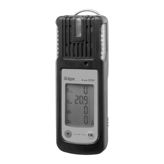
What is What What is What Front panel 1 Gas entry 2 Alarm LED 3 Buzzer 6 Display Rear panel 1 IR interface 2 Fastening clip 3 Type plate 4 Charging contacts 5 Power pack Display 1 Measured gas display 2 Measured value display 3 Special symbols... -
Page 9: Special Symbols
What is What Special Symbols Fault message, refer to page 14 Warning message, refer to page 14 The peak value display for all measuring gases, refer to page 14 The exposure evaluation display (TWA) for measuring gas H S and CO, refer to page 14 The exposure evaluation display (STEL) is switched on for measuring rangasge H and CO, refer to page 14... -
Page 10: Configuration
Different settings can be selected to meet customer requirements on delivery. The current setting can be checked and changed with the software "CC Vision". A version of Dräger CC-Vision which can be used for Dräger X-am 1100/1700/2000 is supplied with the device on CD. -
Page 11: Activating The Device
Charge the rechargeable batteries if necessary, page 42. The Dräger X-am 2000 is ready for operation. Only in the case of Dräger X-am 1100 and Dräger X-am 1700: The following activation sequence also has to be carried out: Press and hold the key for approx. -
Page 12: Operation
Operation Operation Switching on the device Press and hold the key for approx. 3 seconds until the countdown » 3 . 2 . 1 « shown in the display has elapsed. — All the display segments, including the visual, audible and vibration alarms, are activated for a short time. -
Page 13: Before Entering The Workplace
Operation Before entering the workplace CAUTION: Check and, if necessary, adjust the calibration before carrying out safety-relevant measurements. A function test with gas (bump test) must be carried out in accordance with local regulations. Switch on the device. The current measured values are shown in the display. Observe any warning »... -
Page 14: Calling The Info Mode
Operation Calling the Info Mode In measuring mode, press the key for approx. 3 seconds. The peak values as well as the TWA and STEL exposure values are displayed in succession (press the key for the next display). The peak values = the maximum measured values in the case of e.g. CO, H S, ... -
Page 15: Calling The Quick Menu
Operation Calling the Quick Menu — If functions were activated for the quick menu with the PC software "CC Vision" (no functions are activated in the quick menu on delivery): In measuring mode, press the key three times. If no functions have been activated in the quick menu, the device remains in measuring mode. -
Page 16: Calling The Calibration Menu
Operation Calling the Calibration Menu — The calibration menu can only be accessed by entering a password. Password on delivery: » 001 « — The default password on delivery can be changed using the PC software "CC Vision". In measuring mode, press the key for at least 5 seconds. -
Page 17: Calibration Menu Functions
Operation Calibration menu functions Fresh air calibration, refer to page 35 1-button calibration, refer to page 37 Single gas calibration, refer to page 39 Press the key to cancel the active function. — If no key is pressed for 60 seconds, the device returns automatically to measuring mode. -
Page 18: Identifying Alarms
Identifying Alarms Identifying Alarms An alarm is displayed visually, audibly and through vibration in a specific pattern. Concentration pre-alarm A1 The alarm is indicated by an intermittent alarm message: Display » A1 « and measured value alternating: not for O —... -
Page 19: Battery Pre-Alarm
If necessary, commission the Dräger Safety Service Center to eliminate the error. End of operation Only in the case of X-am 1100 and X-am 1700. A warning period starts before the end of the operating time. — After switching on the device, the special symbol »... -
Page 20: Configuring The Device
The installed PC software "CC Vision" is used for configuration. Observe the documentation and online help of the software. — A version of Dräger CC Vision which can be used for X-am 1100/1700/2000 is supplied with the device on CD. -
Page 21: Read Data Base And Display Graphically
Read Data Base and Display Graphically Read Data Base and Display Graphically To read the data base of the device and display it graphically, the device must be connected with a PC. Dräger USB 1.1 GasVision USB DIRA with USB cable (order no. -
Page 22: Faults, Cause And Remedy
Faults, Cause and Remedy Faults, Cause and Remedy Fault Cause Remedy Not possible to switch on the Discharge the power pack Charge the power pack, device page 42. Discharge the alkaline Insert new alkaline batteries, batteries page 41. Not possible to switch off the The device is not set to Select measuring mode. - Page 23 Faults, Cause and Remedy Special symbol » « and Cause Remedy displayed numerical code: DrägerSensor CatEx 125 in Wait until warm-up time is warm-up phase complete. DrägerSensor CatEx 125 in Wait until warm-up time is warm-up phase complete. Ex concentration has drifted Carry out the fresh air into the negative range calibration, page 35.
-
Page 24: Fault Messages
Faults, Cause and Remedy Special symbol » « and Cause Remedy displayed numerical code: DrägerSensor XXS CO in the Wait until warm-up time is warm-up phase complete. DrägerSensor XXS CO in the Wait until warm-up time is warm-up phase complete. CO concentration has drifted Carry out the fresh air into the negative range... - Page 25 Faults, Cause and Remedy Special symbol » « and Cause Remedy displayed numerical code: The zero point calibration of Carry out the fresh air the DrägerSensor CatEx 125 calibration, page 35. is not valid The span calibration of the Carry out the span calibration, DrägerSensor CatEx 125 is page 37 or page 39.
- Page 26 Faults, Cause and Remedy Special symbol » « and Cause Remedy displayed numerical code: DrägerSensor XXS H S is not Check DrägerSensor XXS H inserted page 45. Error during the function test Repeat the function test, with gas (bump test) of the calibrate or replace the DrägerSensor XXS H DrägerSensor XXS H...
-
Page 27: Maintenance
Maintenance Maintenance Maintenance intervals The device should be inspected and maintained by suitably qualified persons every six months (consult: EN 50073 – Guide for the selection, installation, use and maintenance of apparatus for the detection and measurement of combustible gases or oxygen, EN 45544-4 – Electrical apparatus used for the direct detection and direct concentration measurement of toxic gases and vapours - Part 4: Guide for selection, installation, use and maintenance and national regulations). -
Page 28: Carrying Out The Function Test With Gas (Bump Test)
Maintenance Carrying Out the Function Test with Gas (Bump Test) Manual implementation without the documentation of result in the device memory Prepare a test gas cylinder, the volume 0.5 L/min flow must be 0.5 L/min and the gas concentration must be higher than the alarm setpoint concentration to be tested. -
Page 29: Menu Implementation With The Documen-Tation Of Results In The Device Memory
Maintenance Menu implementation with the documen- tation of results in the device memory The setting whether the bump test is to be carried out manually or automatically is made using the PC software Dräger CC Vision. Setting on delivery: automatic bump test. Prepare a test gas cylinder, the volume flow must be 0.5 L/min and the gas concentration must be higher than the... - Page 30 Maintenance For the manual bump test: After the set bump test concentration is reached: Press the key. — The display containing the current gas concentration changes with the display » OK «. — The bump test that was carried out is documented with the result and date in the device memory.
- Page 31 Maintenance For the automatic bump test: After the set bump test concentration is reached: — The display containing the current gas concentration changes with the display » OK «. — The bump test that was carried out is documented with the result and date in the device memory.
-
Page 32: Automatic Implementation With The Bump Test Station
Maintenance Automatic implementation with the Bump Test Station Prerequisite: The device must first be configured for the automatic function test with gas (bump test) using the PC software "CC Vision". — Activate the device for the automatic function test. — Composition of test gas (mixed gas) – standard on delivery: 50 ppm CO, 15 ppm H S, 2.5 vol. - Page 33 Maintenance Remove the device from the Bump Test Station. — If the concentration values have now fallen under the A1 alarm setpoints, the device returns to the measuring mode. — If during the function test no alarm occurs and the current measured values do not reach the set target concentration, the er- ror alarm is activated to indicate failure.
-
Page 34: Calibrating / Adjusting The Device
Maintenance Calibrating / Adjusting the Device Allow the sensors to warm up before the calibration / adjustment! Warm-up time: refer to the Instructions for Use of the installed DrägerSensors (on CD). Calibration interval: — Observe the relevant specifications in the Instructions for Use of the installed DrägerSensors. -
Page 35: Carrying Out The Fresh Air Calibration
Maintenance Carrying out the fresh air calibration To improve the zero point accuracy, you can carry out a fresh air calibration. — Calibrate the device to fresh air, free of measured gases or other interfering gases. — All the sensors are included in the fresh air calibration. - Page 36 Maintenance When the calibration has been completed: — The display containing the current gas concentration changes with the display » OK «. Press the key to confirm the calibration or wait for 5 seconds. If a fault has occurred during the fresh air calibration.
-
Page 37: Carry Out The 1-Button Calibration
Maintenance Carry out the 1-button calibration — All the sensors which can be calibrated are included in the 1-button calibration. The sensors which have not warmed up or which are faulty are not included. — In the case of the 1-button calibration, the sensitivity of all sensors is set to the value of the test gas. - Page 38 Maintenance Open the test gas cylinder valve to let test gas flow over the sensor. — The currently displayed measured values start to flash. The flashing stops after a static measured value has been reached. — The calibration is now carried out automatically.
-
Page 39: Calibrating/Adjusting The Sensitivity For A Single Measuring Channel
Maintenance Calibrating/adjusting the sensitivity for a single measuring channel — The span calibration can be carried out specifically for individual sensors. — In the case of the span calibration, the sensitivity of the selected sensor is set to the value of the used test gas. —... - Page 40 Maintenance Press the key to carry out the calibration of the selected measuring channel. Enter the concentration of the test gas – procedure similar to the enter password procedure. Complete the entry of the concentration by pressing the key. Open the test gas cylinder valve to let test gas flow over the sensor.
-
Page 41: Replacing The Batteries / Rechargeable Batteries
Maintenance Replacing the Batteries / Rechargeable Batteries CAUTION: Do not replace the batteries / rechargeable batteries in hazardous areas. Danger of explosion! Batteries / rechargeable batteries are part of the Ex approval. Only the following types may be used: Alkaline batteries – T4 – (not rechargeable!) Energizer No. -
Page 42: Charging The Rechargeable Batteries
Maintenance Charging the Rechargeable Batteries Caution: Do not charge underground or in explosion-hazard areas! Danger of explosion! The chargers are not designed in accordance with the regulations for firedamp and explosion protection. Even if the device is not used, we recommend that you store the device in the charger (Charging module X-am 1/2/5000, order no. - Page 43 Maintenance — Always connect or disconnect the charging modules individually and not in groups in order to prevent the charging station from becoming damaged. During transportation, the power pack and the charging modules should also always be handled individually and without inserted devices.
-
Page 44: Charging With Charging Module And Plug-In Power Pack Or Vehicle Charging Adapter
Maintenance Charging with charging module and plug-in power pack or vehicle charging adapter — When using the power pack (order no. 83 16 994), up to 5 devices can be charged at the same time, with power pack (order no. 83 15 635) up to 2 devices. —... -
Page 45: Replacing The Sensors
Replacing the Sensors Replacing the Sensors Switch off the device: keep the key key depressed at the same time. Loosen the screw (2.5 mm hexagon socket) on the power pack and remove the power pack. Loosen the 4 screws (1.5 mm hexagon socket) on the rear panel of the device. - Page 46 Replacing the Sensors Next: Carry out the fresh air calibration, page 35. and then: Calibrate the sensitivity: either carry out the 1-button calibration, page 37 calibrate/adjust the sensitivity, page 39. Electrochemical sensors — Do not expose to fire, — Do not force open. Danger! Acid-Burn Risk! —...
-
Page 47: Care
Care Care The device does not need any special maintenance. Dirt and deposits can be removed from the device by washing it with cold water. A sponge can be used for wiping if necessary. ATTENTION: Abrasive cleaning implements (brushes etc.), cleaning agents and cleaning solvents can destroy the dust and water filters. -
Page 48: Disposing Of The Device
Disposing of the Device Disposing of the Device EU-wide regulations for the disposal of electric and electronic appliances which have been defined in the EU Directive 2002/ 96/EG and in national laws are effective from August 2005 and apply to this device. Common household appliances can be disposed of using special collecting and recycling facilities. -
Page 49: Technical Data
Technical Data Technical Data Ambient conditions: during operation and –20 to 50 C or –20 to 40 storage (dependent on the battery pack and installed batteries) 700 to 1300 hPa 10 to 95% relative humidity Device data Protection class IP 67 for devices with sensors Intensity of alarm Typically 90 dB (A) in 30 cm distance Operation time... -
Page 50: Sensor Data
Technical Data Sensor Data Extract! See the Instructions for Use of the used sensors for details. ≤8 seconds ≤6 seconds ≤6 seconds ≤6 seconds Reaction time, t 0...50 Measuring accuracy ≤5 ≤1 ≤2 ≤2 [% of the measured value] Temperature influence ≤±0.2 vol. -
Page 51: Order List
Order List Order List Name and Description Order no. Dräger X-am 1100 83 18 710 The maintenance-free 120 day 4-gas measuring device is equipped with an alkaline power pack and an O , Ex, CO and H S sensor. Dräger X-am 1700... -
Page 52: Accessories
Order List Name and Description Order no. Power supply units: NiMH power pack T4 83 18 704 Alkaline power pack T3/T4 (without alkaline batteries) 83 18 703 Alkaline batteries T4 (2 pcs.) for alkaline power pack 83 18 708 Rechargeable battery and charging kit (contains NiMH power 83 18 785 pack T4, charging module for Dräger X-am 1/2/5000 and plug- in power adapter) -
Page 53: Spare Parts
Order List Name and Description Order no. Tester 90 83 16 532 Float probe with accessories 83 18 371 Viton hose 12 03 150 Hose (not suitable for H 11 80 681 Accessories for measured value acquisition and configuration: GasVision 83 14 034 CC Vision 64 08 815... -
Page 54: Declaration Of Conformity
Declaration of Conformity Declaration of Conformity... - Page 55 Declaration of Conformity...
- Page 56 Index Index 1-button calibration (1-button cal) ......... . . 17 Accessories .
- Page 57 Index Disposal ..............48 DrägerSensor CatEx 125 .
- Page 58 Index Order List ..............51 Oxygen-enriched atmosphere .
- Page 59 Index Technical Data ..............49 Temperature influence .
- Page 60 Dräger Safety AG & Co. KGaA Revalstraße 1 D-23560 Lübeck Germany Tel. +49 451 8 82- 0 +49 451 8 82- 20 80 www.draeger-safety.com 90 23 854 - GH 4638.200 en © Dräger Safety AG & Co. KGaA 1st edition - February 2006 Subject to alteration...
Need help?
Do you have a question about the X-am 1100 and is the answer not in the manual?
Questions and answers