Drager X-am 5000 Technical Manual
Multi-gas monitor approved as type mqg 0010
Hide thumbs
Also See for X-am 5000:
- User manual ,
- Instructions for use manual (292 pages) ,
- Technical manual (60 pages)
Table of Contents
Advertisement
Advertisement
Table of Contents

Related Manuals for Drager X-am 5000

Summary of Contents for Drager X-am 5000
- Page 1 ® Dräger X-am 5000 approved as type MQG 0010 Multi-Gas Monitor Technical Manual...
-
Page 2: Table Of Contents
Content Content For Your Safety ........... . . 4 Intended Use . - Page 3 Content Fault messages ........... . . 33 Maintenance .
-
Page 4: For Your Safety
For Your Safety For Your Safety General safety statements Before using this product, carefully read the associated Instructions for Use. This document does not replace the Instructions for Use. Definitions of alert icons The following alert icons are used in this document to provide and highlight areas of the associated text that require a greater awareness by the user. -
Page 5: Tests And Approvals
Tests and Approvals Tests and Approvals Copies of the name plate and the declaration of conformity are provided in the enclosed supplementary documentation (order no. 90 33 890). The BVS 10 ATEX E 080 X technical suitability test is based on the adjustment with the target gas. -
Page 6: Intended Operating Area And Operating Conditions
Tests and Approvals Intended operating area and operating conditions Areas subject to explosion hazards, classified by zones The instrument is intended for the use in explosion-hazard areas of Zone 0, Zone 1 or Zone 2 or in mines at risk due to fire damp. It is intended for use within a temperature range of -20 °C to +50 °C, and for areas in which gases of explosion groups IIA, IIB or IIC and temperature class T3 or T4 (depending on the batteries and rechargeable battery) may be present. - Page 7 Tests and Approvals CAUTION Use only supply units ABT 0100 (83 22 237), HBT 0000 (83 18 704) or HBT 0100 (83 22 244). Check the supply unit for approved batteries and applicable temperature class. Note the following for CSA (Canadian Standards Association) applications: For the CSA approval only the functions of the device component that is used to measure flammable gases are tested.
-
Page 8: What Is What
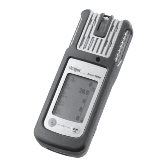
What is What What is What Front panel Gas entry Alarm LED Buzzer X-am 5000 Display Tool for replacing the sensor Rear panel IR interface Fastening clip Type plate Charging contacts Power pack Serial no. Display for 5 measuring channels only: Measured gas %LEL... -
Page 9: Special Symbols
What is What Special symbols Fault message, refer to page 17 Warning message, refer to page 17 The peak value display for all measuring gases, refer to page 17 The exposure evaluation display (TWA) for measuring gases, e.g., H S and refer to page 17 The exposure evaluation display (STEL) for measuring gases, e.g,. -
Page 10: Configuration
Configuration Configuration Standard gas configuration DrägerSensor Measuring Alarm A1 Alarm A2 range CatEx 125 PR 0 to 100 [%LEL] CatEx 125 PR Gas 0 to 100 [%LEL] XXS O [vol. %] 0 to 25 XXS O 100 [vol. %] 0 to 100 18.5 XXS O LS / CO-LC... - Page 11 Configuration DrägerSensor Measuring Alarm A1 Alarm A2 range XXS OV [ppm] 0 to 200 XXS OV A [ppm] 0 to 200 XXS Odorant [ppm] 0 to 40 XXS Amine [ppm] 0 to 100 XXS COCI [ppm] 0 to 10 XXS O [ppm] 0 to 10 XXS NO...
-
Page 12: Standard Device Configuration
Configuration Standard device configuration NOTICE Only trained personnel are permitted to make changes to the device configuration. ® Dräger X-am 5000 Bump test mode Extended bump test Fresh air calibration 2) 3) Operating signal Capture range Switch off allowed LEL factor 4.4 (vol. -
Page 13: Operation
Operation Operation Preparations for operation Before using the instrument for the first time, insert a charged NiMH T4 power pack or batteries approved by Dräger, see "Changing the batteries" on page 55. The instrument is now ready for operation. WARNING To reduce the risk of ignition of a flammable or explosive atmosphere, strictly adhere to the following warning statements:... -
Page 14: Switching Off The Device
Operation Switching off the device Press and hold the key and key at the same time until the countdown » 3 . 2 . 1 « shown in the display has elapsed. Before the device is switched off, the visual, audible and vibration alarms are activated for a short time. - Page 15 Operation Check that the gas inlet opening on the device is not covered. WARNING Explosion hazard! To reduce the risk of flammable or explosive atmospheres igniting, it is essential that the warning notices below are observed: Fractions of catalytic poisons in the measuring gas (e.g. volatile silicon, sulphur, heavy metal compounds or halogenated hydrocarbon) can damage the Cat Ex sensor.
-
Page 16: During Operation
Operation During operation During operation, the measured values for every measured gas are displayed. In the event of an alarm, the corresponding displays, the visual, audible and vibration alarms are activated – see chapter “Identifying Alarms”. If a measuring range is exceeded or a negative drift occurs, the following displays are shown instead of the measured value display: »... -
Page 17: Calling The Info Mode
Operation Calling the Info Mode In measuring mode, press the key for approx. 3 seconds. If any warning or fault messages exist, the corresponding information or error codes are displayed (page 30 to page 37). Press the key successively for the next display. The peak values and the exposition values TWA and STEL are displayed. -
Page 18: Calling The Quick Menu
Operation Calling the Quick Menu Only the fresh air calibration is activated in the quick menu on delivery. The PC software Dräger CC Vision can be used to activate the bump test for the quick menu and/or the function for displaying and deleting peak values. ... -
Page 19: Quick Menu "Delete Peak Values
Operation Quick menu "Delete peak val- ues" After the function has been selected, the current peak values are displayed; the peak values special symbol appears in %LEL the display at the same time. Vol% The peak values can be deleted by pressing the key for 5 sec. -
Page 20: Calling The Calibration Menu
Operation Calling the Calibration Menu The calibration menu can only be accessed by entering a password. Password on delivery: » 001 « The default password on delivery can be changed using the PC software Dräger CC Vision. In measuring mode, press the key for at least 4 seconds. -
Page 21: Identifying Alarms
Identifying Alarms Identifying Alarms An alarm is displayed visually, audibly and through vibration in a specific pattern. NOTICE At low temperatures the legibility of the display can be improved by switching on the backlight. Concentration pre-alarm A1 The alarm is indicated by an intermittent alarm message: Display »... -
Page 22: Stel / Twa Exposure Alarm
Identifying Alarms STEL / TWA exposure alarm The alarm is indicated by an intermittent alarm message: Display » A2 « and » « (TWA) or » « (STEL) and measured value alternating: CAUTION Health hazard! Leave the area immediately. After this alarm, the deployment of personnel is subject to the relevant national regulations. -
Page 23: Operation With Pump
Operation with pump Operation with pump Observe the following when performing measurements using the pump Perform visual inspection of the probe, if necessary. Wait for the flushing time to end. Flush the Dräger sampling hose or Dräger probes prior to each measurement with the air sample to be measured. - Page 24 Operation with pump Performing a measurement with the Dräger X-am Pump Required accessories (siehe “Accessories” auf Seite 66): Dräger X-am Pump Sampling hose and probes Pump symbols: Pump battery 100 % charged Warning for pump (Gas detector can no longer detect pump.) Remaining charge of pump Leak test:...
- Page 25 Operation with pump WARNING Impairment of accuracy! After measuring high concentrations of nonane (>20 %LEL), the accuracy for measuring nonane is impaired. The pump is not suitable for long-term measurement of high concentrations of nonane. Performing a measurement with a manual pump adapter and rubber ball pump Required accessories (siehe “Accessories”...
-
Page 26: Configuring The Device
Configuring the Device Configuring the Device To individually configure a device with standard configuration, the device must be connected with a PC. Dräger USB 2.0 CC-Vision USB DIRA with USB cable (order no. 83 17 409) Dräger USB 2.0 CC-Vision Calibration cradle (order no. -
Page 27: Device Settings
Configuring the Device Device settings NOTICE Only trained personnel are permitted to make changes to the device configuration. The following changes can be made to the device parameters for a device: Designation Field Password Numeric field (3-figure) Operating signal LED Yes/No Operating signal horn Yes/No... - Page 28 Configuring the Device Delay until error after expiry of cal. interval 0 - 10 (days) Activate user service life Yes/No User service life (days) 0 - 999 (if activated) Running in Yes/No LEL category “---” or “PTB” or “IEC” or “NIOSH” (if this is changed, the LEL factor will be altered to match) At least one of the two operating signals must be switched on.
-
Page 29: Read Database And Display Graphically
Read Database and Display Graphically Read Database and Display Graphically To read the database of the device and display it graphically, the device must be connected with a PC. Dräger USB 2.0 GasVision USB DIRA with USB cable (order no. 83 17 409) Dräger USB 2.0 GasVision... -
Page 30: Faults, Cause And Remedy
Faults, Cause and Remedy Faults, Cause and Remedy Fault Cause Remedy Not possible to switch on Discharge the power pack Charge the power pack, the device page 56. Discharge the alkaline Insert new alkaline batteries, batteries page 55. Not possible to switch off The device is not set to Select measuring mode. - Page 31 Faults, Cause and Remedy Special symbol » « Cause Remedy and displayed numerical code: DrägerSensor CatEx 125 PR Wait until warm-up time is in warm-up phase complete. DrägerSensor CatEx 125 PR Wait until warm-up time is in warm-up phase complete. Ex concentration has drifted Carry out fresh air calibration, into the negative range...
- Page 32 Faults, Cause and Remedy Special symbol » « Cause Remedy and displayed numerical code: The temperature is too high Operate the device within the allowed temperature range. The temperature is too low Operate the device within the allowed temperature range. The calibration interval for Carry out span calibration for DrägerSensor XXS EC2 has...
-
Page 33: Fault Messages
Faults, Cause and Remedy Special symbol » « Cause Remedy and displayed numerical code: The calibration interval for Carry out span calibration for DrägerSensor XXS EC 4 has DrägerSensor XXS EC 4, elapsed page 50. Alarm setpoint A2 setting is Set alarm setpoint to less than greater than 60 %LEL 60 %LEL. - Page 34 Faults, Cause and Remedy Special symbol » « Cause Remedy and displayed numerical code: User parameters not feasible Check configuration of user parameters and adjust Flow alarm of X-am Pump Check the gas circuit for obstructions and replace filters if necessary.
- Page 35 Faults, Cause and Remedy Special symbol » « Cause Remedy and displayed numerical code: The zero point calibration of Carry out fresh air calibration, DrägerSensor XXS EC1 is not page 46. valid The span calibration of Carry out span calibration. Carry DrägerSensor XXS EC1 is not out page 50 or fresh air calibra- valid...
- Page 36 Faults, Cause and Remedy Special symbol » « Cause Remedy and displayed numerical code: User parameters not feasible Check configuration of user parameters and adjust Device incorrectly configured Change sensor for applicable by Dräger CC-Vision. channel with Dräger CC-Vision. Error during warm-up acceler- Disconnect and reconnect ation Dräger Sensor XXS power pack or replace the sen-...
- Page 37 Faults, Cause and Remedy Special symbol » « Cause Remedy and displayed numerical code: The zero point calibration of Carry out fresh air calibration, DrägerSensor XXS EC4 is not page 46. valid The span calibration of Carry out span calibration, DrägerSensor XXS EC4 is not page 50.
-
Page 38: Maintenance
Maintenance Maintenance Maintenance intervals The device should be inspected and maintained by suitably qualified persons annually. Comparisons: EN 60079-29-2 – Gas detectors - Selection, installation, use and maintenance of detectors for flammable gases and oxygen EN 45544-4 – Electrical apparatus used for the direct detection and direct concentration measurement of toxic gases and vapours - Part 4: Guide for selection, installation, use and maintenance ... -
Page 39: Toxictwins
Maintenance ToxicTwins When the ToxicTwins feature is activated, the measuring channels of the XXS CO sensor and the XXS HCN sensor are offset against each other in such a manner that the device issues an alarm before the respective A1 alarm threshold is reached if both gases are detected at the same time. -
Page 40: Carry Out Manual Bump Test
Maintenance Carry out manual bump test Manual implementation without the documentation of results in the device memory Prepare a test gas cylinder, the 0.5 L/min volume flow must be 0.5 L/min and the gas concentration must be higher than the alarm setpoint concentration to be tested. -
Page 41: Menu Implementation With The Documentation Of Results In The Device Memory
Maintenance Calibrating the device, refer to page 45. NOTICE To check the measured value response times, apply t90 test gas to the X-am via the calibration cradle. Check the results in accordance with the information in the table in the enclosed supplementary documentation (order no. 90 33 890) until 90 % of the end display is reached. - Page 42 Maintenance The current gas concentration values and the special symbol » « (for bump test) flash. %LEL Press the key to start the function test with gas. Vol% Open the test gas cylinder valve to let test gas flow over the sensor. ...
-
Page 43: Automatic Implementation With The Bump Test Station
Maintenance Automatic implementation with the Bump Test Station Prerequisite: The device must first be configured for the automatic function test with gas (bump test) using the PC software Dräger CC Vision. Activating the device for the automatic function test. ... - Page 44 Maintenance Remove the device from the Bump Test Station. If the concentration values have now fallen under the A1 alarm setpoints, the device returns to the measuring mode. An error will be triggered if the preset bump test concentration is not reached within the specified time.
-
Page 45: Calibrating The Device
Maintenance Calibrating the Device NOTICE Dräger recommends using the extended bump test for cross calibrations (Dräger X- dock technical manual). Calibration may not be possible due to device and channel errors. Allow the sensors to warm up before the calibration! Warm-up time: see Instructions for Use/data sheets of the installed DrägerSensors (at www.draeger.com). -
Page 46: Carrying Out The Fresh Air Calibration
Maintenance Carrying out the fresh air calibration To improve the zero point accuracy, you can carry out a fresh air calibration. NOTICE If none of the sensors fitted permits calibration with fresh air (e.g. only O , only IR- ), fresh air calibration is not offered as a menu function. ... - Page 47 Maintenance The display containing the current gas concentration changes with the display » OK «. %LEL Press the key to confirm the calibration or wait for approx. 5 Vol% seconds. If a fault occurred during the fresh air calibration.
- Page 48 Maintenance Automatic fresh air calibration of the CatEx sensor in the charging cradle This feature is used to perform an automatic fresh air calibration of the CatEx sensor after placing it in the charging cradle. The feature can be adjusted using the Dräger CC-Vision PC software.
-
Page 49: Carrying Out 1-Button Calibration
Maintenance Carrying out 1-button calibration NOTICE If no sensors are enabled for 1-button calibration by the Dräger CC Vision PC program, the 1-button calibration menu function will not be offered. All sensors that are enabled by the Dräger CC Vision PC program take part in the 1- button calibration. - Page 50 Maintenance Open the test gas cylinder valve to let test gas flow over the sensor. The currently displayed measured values start to flash. The flashing stops after a static measured value has been reached. The calibration is now carried out automatically. ...
-
Page 51: Calibrating The Sensitivity For An Individual Measuring Channel
Maintenance Calibrating the sensitivity for an individual measuring channel The span calibration can be carried out specifically for individual sensors. In the case of the span calibration, the sensitivity of the selected sensor is set to the value of the test gas used. ... -
Page 52: Span Calibration For Catex
Maintenance Span calibration for CatEx If the measuring range end value < = 100%LEL, the adjustment for the heat tinting is offered. Display in the case of channel selection: Open the test gas cylinder valve to let %LEL test gas flow over the sensor. - Page 53 Maintenance If a fault occurred during the span calibration. The fault message » « appears %LEL and » « is displayed for the sensor instead of the measured value. In this case, repeat the calibration. Vol% If necessary, replace the sensor, page 59.
- Page 54 Maintenance Note on the use in underground mining: When calibrating the Ex channel to methane as the measured gas, the indication on the instrument must be set to a value 5 % (relative) higher than the test gas concentration used. Automatic fresh air calibration in the charging cradle (CatEx sensor only): Calibrate the gas detector to fresh air, free of measured gases or other interfering gases.
-
Page 55: Replacing The Batteries / Rechargeable Batteries
Maintenance Replacing the batteries / rechargeable batteries WARNING Explosion hazard! To reduce the risk of flammable or explosive atmospheres igniting, it is essential that the warning notices below are observed: Do not throw used batteries into fire or try to open them by force. Do not replace or charge batteries in areas at risk of an explosion hazard. -
Page 56: Charging The Rechargeable Batteries
Maintenance Charging the rechargeable batteries WARNING Explosion hazard! To reduce the risk of flammable or explosive atmospheres igniting, it is essential that the warning notices below are observed: Do not charge underground or in explosion-hazard areas! Danger of explosion! The chargers are not designed in accordance with the regulations for firedamp and explosion protection. - Page 57 Maintenance X-am 5000 X-am 5000 X-am 5000 %LEL %LEL %LEL Vol% Vol% Vol% Attach additional charging modules in the same way. Always connect or disconnect the charging modules individually and not in groups in order to prevent the charging station from becoming damaged. During transportation, the power pack and the charging modules should also always be handled individually and without inserted devices.
-
Page 58: Adapter
Maintenance In the event of a short circuit or if the power pack is overloaded: The red "Overload" LED lights, and an audible alarm sounds. After the fault has been corrected, the alarm is switched off automatically and the charging process is restarted. -
Page 59: Replacing The Sensors
Replacing the Sensors Replacing the Sensors CAUTION Damage to components! There are components in the instrument that are sensitive to electric charge. Before opening the instrument to replace the sensor, ensure that the person performing the work is earthed to avoid damage to the device. Earthing can be safely ensured, e. g. via an ESD workstation (electrostatic discharge). - Page 60 Replacing the Sensors Next: Carry out a fresh air calibration, page 46. and then: Calibrate the sensitivity: either carry out 1-button calibration, page 47 carry out span calibration, page 50. Electrochemical sensors WARNING Do not throw into fire, Do not force open.
-
Page 61: Sensor Warm-Up Acceleration
Sensor warm-up acceleration Sensor warm-up acceleration There is a function available for accelerating the warm-up procedure for selected EC sensors. The function shortens the time taken until the unit is ready to make measurements, i.e. the time taken to save the display and alarm evaluation of the measurements. -
Page 62: Cleaning
Cleaning Start of the warm-up acceleration. The remaining time is displayed and decremented. WARNING This function requires that the device is in a gas-free environment. A warning screen is displayed and the remaining time during which no gas may be applied is shown It is essential to 04:08 ensure that the sensor is in the fresh air... -
Page 63: Storage
Storage Storage Dräger recommends storing the instrument in the charger module (order no. 83 18 639). Dräger recommends checking the charge of the power supply at least every three weeks if the instrument is not stored in the charger module. Disposal This product must not be disposed of as municipal waste. -
Page 64: Technical Data
Technical Data Technical Data X-am 5000 Ambient conditions: during operation and Temperature class T4 (-20 to +50 °C): storage NiMH power packs type: HBT 0000, HBT 0100 Power pack type: ABT 0100 with alkaline single cell type: Duracell Procell MN 1500 Duracell Plus Power MN 1500 Temperature class T3 (-20 to +40 °C): Power pack type: ABT 0100... -
Page 65: Order List
Order List Order List Name and description Order no. Dräger X-am 5000 83 20 000 Unlimited multi gas detector for 1 to 5 gases with replaceable sensors. With selectable special calibration. Default calibration for the ex-sensor: methane. With default alarm thresholds that can be adjusted specifically for each country. -
Page 66: Accessories
Order List Name and description Order no. Accessories The accessories are not part of BVS10 ATEX E 080X and PFG 10 G 001X. Pump accessories: Dräger Pump X-am 1/2/5000 83 19 400 Case for Dräger Pump X-am 1/2/5000 83 19 385 Dräger X-am Pump 83 27 100 Case for Dräger X-am Pump... - Page 67 Order List Name and description Order no. Fluoroelastomer hose (3 mm) incl. adapter, 5 m 83 25 705 Fluoroelastomer hose (3 mm) incl. adapter, 10 m 83 25 706 Fluoroelastomer hose (3 mm) incl. adapter, 20 m 83 25 707 Fluoroelastomer hose (3 mm), sold by the metre, specify 83 25 837...
-
Page 68: Spare Parts
Order List Name and description Order no. Spare parts DrägerSensor CatEx 125 PR, 0 to 100 %LEL 68 12 950 (or 0 to 100 vol.% methane) DrägerSensor Cat Ex 125 PR Gas, 0 to 100 %LEL 68 13 080 DrägerSensor XXS O , 0 to 25 vol.% 68 10 881 DrägerSensor XXS O... - Page 72 Dräger Safety AG & Co. KGaA Revalstraße 1 D-23560 Lübeck Germany Phone +49 451 8 82- 0 +49 451 8 82- 20 80 www.draeger.com 90 23 999 - TM 4638.210 en © Dräger Safety AG & Co. KGaA Edition 16 - January 2018 (Edition 01 - April 2007) Subject to alteration...
Need help?
Do you have a question about the X-am 5000 and is the answer not in the manual?
Questions and answers