Dräger X-am 1700 Technical Manual
Multi-gas monitor
Hide thumbs
Also See for X-am 1700:
- Technical handbook (60 pages) ,
- Instructions for use manual (121 pages)

Subscribe to Our Youtube Channel
Related Manuals for Dräger X-am 1700


Summary of Contents for Dräger X-am 1700
- Page 1 ® Dräger X-am 1700, 2000 approved as type LQG 00xx Multi-Gas Monitor Technical Manual...
-
Page 2: Table Of Contents
Content Content For Your Safety ........... . . 4 Safety symbols used in these Technical Manual . - Page 3 Content Faults, Cause and Remedy ......... . . 23 Warning messages .
-
Page 4: For Your Safety
For Your Safety For Your Safety Strictly follow the Instructions for Use Any use of the device requires full understanding and strict observation of the Instructions for Use supplied with the device. The device is only to be used for the purposes specified here. Maintenance The maintenance intervals and measures stated in this Technical Handbook as well as the specifications in the Instructions for Use of the used DrägerSensors... -
Page 5: Intended Use
X-am 1700: independent measurement of four gases. X-am 1700: 2 years service life from activation of the device (refer to page 11). X-am 2000 depending on the device type: independent measurement of one gas up to four gases. -
Page 6: Tests And Approvals
Tests and Approvals Tests and Approvals Marking Power pack 83 18 703; РОСС ГБ05. B03849 approved as type ABT 0000 Ex d ia I Mb X Temperature class T4 Ex d ia IIC T4(T3) Gb X ГБ05 C ≤ Ta ≤ +50 –20 use with alkaline batteries Type: LQG 0000... -
Page 7: Intended Operating Area And Operating Conditions
Tests and Approvals Intended Operating Area and Operating Conditions Hazardous areas classified by zones The device is intended to be used in hazardous areas or mines susceptible to firedamp clas- sified zone 1 or zone 2, within a temperature range of –20 C to +50 C or –20 C to +50... -
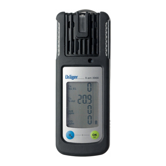
Page 8: What Is What
What is What What is What Front panel Gas entry Alarm LED Buzzer Display Rear panel IR interface Fastening clip Type plate Charging contacts Power pack Display Measured gas display Measured value display Special symbols... -
Page 9: Special Symbols
What is What Special Symbols Fault message, refer to page 14 Warning message, refer to page 14 The peak value display for all measuring gases, refer to page 14 The exposure evaluation display (TWA) for measuring gas H S and CO, refer to page 14 The exposure evaluation display (STEL) is switched on for measuring rangasge H and CO, refer to page 14... -
Page 10: Configuration
Different settings can be selected to meet customer requirements on delivery. The current setting can be checked and changed with the software "CC Vision". A version of Dräger CC-Vision which can be used for Dräger X-am 1700/2000 is supplied with the device on CD. -
Page 11: Activating The Device
Charge the rechargeable batteries if neces- sary, page 43. The Dräger X-am 2000 is ready for opera- tion. Only in the case of Dräger X-am 1700: The following activation sequence also has to be carried out: ● Press and hold the key for approx. -
Page 12: Operation
— The device performs a self test. — The remaining operating time is displayed, e.g. » d 730 « (remaining operating time 730 days). This applies to Dräger X-am 1700 and if the service life is activated in Dräger X-am 2000. -
Page 13: Before Entering The Workplace
Operation Before entering the workplace CAUTION Check and, if necessary, adjust the calibration before carrying out safety-relevant measure- ments. A function test with gas (bump test) must be carried out in accordance with local regulations. ● Switch on the device. The current measured values are shown in the display. ●... -
Page 14: Calling The Info Mode
Operation Calling the Info Mode ● In measuring mode, press the key for approx. 3 seconds. Any information and fault codes, the peak values as well as the TWA and STEL exposure values are displayed in succession (press the key for the next display). If any warning or fault messages exist, the corresponding note or error codes are displayed (page 23 to page 27). -
Page 15: Calling The Quick Menu
Operation Calling the Quick Menu — If functions were activated for the quick menu with the PC software "CC Vision" (no functions are activated in the quick menu on delivery): ● In measuring mode, press the key three times. If no functions have been activated in the quick menu, the device remains in measuring mode. -
Page 16: Calling The Calibration Menu
Operation Calling the Calibration Menu — The calibration menu can only be ac- cessed by entering a password. Password on delivery: » 001 « — The default password on delivery can be changed using the PC software "CC Visi- on". ●... -
Page 17: Calibration Menu Functions
Operation Calibration menu functions Fresh air calibration, refer to page 36 1-button calibration, refer to page 38 Single gas calibration, refer to page 40 ● Press the key to cancel the active function. — If no key is pressed for 10 minutes, the device returns automatically to measuring mode. -
Page 18: Identifying Alarms
Identifying Alarms Identifying Alarms An alarm is displayed visually, audibly and through vibration in a specific pattern. Concentration pre-alarm A1 The alarm is indicated by an intermittent alarm message: Display » A1 « and measured value alternating: not for O —... -
Page 19: Battery Pre-Alarm
If necessary, commission the Dräger Safety Service Center to eliminate the error. End of operation Only in the case of X-am 1700. A warning period starts before the end of the operating time. — After switching on the device, the special symbol »... -
Page 20: Pump Operation
Pump Operation Pump Operation With Dräger X-am 125 pump Accessories: Dräger X-am 125 pump, sampling hose and probes, see Order List, see “Accessories” on page 53 Commissioning and performing the measurement: ● see the Instructions for Use of the Dräger X-am 125. With hand pump adapter and rubber ball pump Accessories: Hand pump adapter, rubber ball pump, sampling hose and probes, see Order List, see... -
Page 21: Configuring The Device
The installed PC software "CC Vision" is used for configuration. ● Observe the documentation and online help of the software. — A version of Dräger CC Vision which can be used for X-am 1700/2000 is supplied with the device on CD. -
Page 22: Read Data Base And Display Graphically
Read Data Base and Display Graphically Read Data Base and Display Graphically To read the data base of the device and display it graphically, the device must be connected with a PC. Dräger USB 1.1 GasVision USB DIRA with USB cable (order no. -
Page 23: Faults, Cause And Remedy
Faults, Cause and Remedy Faults, Cause and Remedy Fault Cause Remedy Not possible to switch on the Discharge the power pack Charge the power pack, device page 43. Discharge the alkaline batte- Insert new alkaline batteries, ries page 42. Not possible to switch off the The device is not set to Select measuring mode. - Page 24 Faults, Cause and Remedy Special symbol » « and Cause Remedy displayed numerical code: Ex concentration has drifted Carry out the fresh air calibra- into the negative range tion, page 36. The temperature is too high Operate the device within the allowed temperature range.
-
Page 25: Fault Messages
Faults, Cause and Remedy Special symbol » « and Cause Remedy displayed numerical code: DrägerSensor XXS CO in the Wait until warm-up time is warm-up phase complete. CO concentration has drifted Carry out the fresh air calibra- into the negative range tion, page 36. - Page 26 Faults, Cause and Remedy Special symbol » « Cause Remedy and displayed numerical code: The span calibration of the Carry out the span calibration, DrägerSensor CatEx 125 PR page 38 or page 40. is not valid The measurement value of the Carry out the fresh air calibra- DrägerSensor CatEx 125 PR tion, page 36.
- Page 27 Faults, Cause and Remedy Special symbol » « Cause Remedy and displayed numerical code: Measured value of the Dräger- Carry out the fresh air calibra- Sensor XXS H S is in the tion, page 36. negative range DrägerSensor XXS H S is not Check DrägerSensor XXS H inserted...
-
Page 28: Maintenance
Maintenance Maintenance Maintenance intervals The device should be inspected and maintained by suitably qualified persons every six months (consult: EN 60079-29-2 – Gas measuring device - Selection, installation, use and maintenance of apparatus for the measurement of combustible gases or oxygen, EN 45544-4 –... -
Page 29: Carrying Out The Function Test With Gas (Bump Test)
Maintenance Carrying Out the Function Test with Gas (Bump Test) Manual implementation without the documentation of result in the device memory ● Prepare a test gas cylinder, the volume flow must be 0.5 L/min and the gas con- 0.5 L/min centration must be higher than the alarm setpoint concentration to be tested. -
Page 30: Menu Implementation With The Documen-Tation Of Results In The Device Memory
Maintenance Menu implementation with the docu- men-tation of results in the device memory The "Quick bump test" or the "Extended bump test" is selected using the Dräger CC Vision PC software. The "Quick bump test" checks whether the gas concentration has exceeded the Alarm 1 threshold (with oxy- gen, the check is whether the concentration has fallen below the Alarm 1 threshold). - Page 31 Maintenance — The current gas concentration values and the special symbol » « (for bump test) flash. ● Press the key to start the function test with gas. ● Open the test gas cylinder valve to let test gas flow over the sensor. —...
- Page 32 Maintenance For the automatic bump test: After the set bump test concentration is reached: — The display containing the current gas concentration changes with the display » OK «. — The bump test that was carried out is do- cumented with the result and date in the device memory.
-
Page 33: Automatic Implementation With The Bump Test Station
Maintenance Automatic implementation with the Bump Test Station Prerequisite: The device must first be configured for the automatic function test with gas (bump test) using the PC software "CC Vision". — Activate the device for the automatic function test. — Composition of test gas (mixed gas) – standard on delivery: 50 ppm CO, 15 ppm H S, 2.5 vol. - Page 34 Maintenance ● Remove the device from the Bump Test Station. — If the concentration values have now fal- len under the A1 alarm setpoints, the de- vice returns to the measuring mode. — If during the function test no alarm occurs and the current measured values do not reach the set target concentration, the er- ror alarm is activated to indicate failure.
-
Page 35: Calibrating / Adjusting The Device
Maintenance Calibrating / Adjusting the Device Calibration may not be possible due to device and channel errors. Allow the sensors to warm up before the calibration / adjustment! Warm-up time: refer to the Instructions for Use of the installed DrägerSensors (on CD). Calibration interval: —... -
Page 36: Carrying Out The Fresh Air Calibration
Maintenance Carrying out the fresh air calibration To improve the zero point accuracy, you can carry out a fresh air calibration. — Calibrate the device to fresh air, free of measured gases or other interfering ga- ses. — All the sensors are included in the fresh air calibration. - Page 37 Maintenance — The display containing the current gas concentration changes with the display » OK «. ● Press the key to confirm the calibrati- on or wait for 5 seconds. If a fault has occurred during the fresh air calibration. —...
-
Page 38: Carry Out The 1-Button Calibration
Maintenance Carry out the 1-button calibration — All the sensors which can be calibrated are included in the 1-button calibration. The sensors which have not warmed up or which are faulty are not included. — In the case of the 1-button calibration, the sensitivity of all sensors is set to the value of the test gas. - Page 39 Maintenance When the calibration is completed and the displayed measured values are stab- — The display containing the current gas concentration changes with the display » OK «. ● Press the key or wait for 5 minutes to quit the calibration. —...
-
Page 40: Calibrating/Adjusting The Sensitivity For A Single Measuring Channel
Maintenance Calibrating/adjusting the sensitivity for a single measuring channel — The span calibration can be carried out specifically for individual sensors. — In the case of the span calibration, the sensitivity of the selected sensor is set to the value of the used test gas. —... - Page 41 Maintenance ● Press the key to carry out the calibra- tion of the selected measuring channel. — The calibration gas concentration is dis- played. ● Press the [OK] key to confirm the cali- bration gas concentration or use the [ + ] key to change the calibration gas concen- tration and complete the process by pres- sing the [OK] key.
-
Page 42: Replacing The Batteries / Rechargeable Batteries
Maintenance Replacing the Batteries / Rechar- geable Batteries WARNING Do not replace the batteries / rechargeable batteries in hazardous areas. Danger of explo- sion! Batteries / rechargeable batteries are part of the Ex approval. Only the following types may be used: Alkaline batteries –... -
Page 43: Charging The Rechargeable Batteries
Maintenance Charging the Rechargeable Batteries WARNING Do not charge underground or in explosion-hazard areas! Danger of explosion! The chargers are not designed in accordance with the regulations for firedamp and explo- sion protection. Even if the device is not used, we recommend that you store the device in the charger (Char- ging module X-am 1/2/5000, order no. - Page 44 Maintenance ● Position the device on an even and level surface. ● Connecting the power pack to the mains. The green "Mains" LED lights. ● Insert the device into the charging modu- Display LED on the charger: Charge Fault Full If a fault occurs: Remove the device from the charging module and insert it again.
-
Page 45: Adapter
Maintenance Charging with charging module and plug-in power pack or vehicle charging adapter — When using the power pack (order no. 83 16 994), up to 5 devices can be charged at the same time, with power pack (order no. 83 15 635) up to 2 devices. —... -
Page 46: Replacing The Sensors
Replacing the Sensors Replacing the Sensors ● Switch off the device: keep the key and the key depressed at the same time. ● Loosen the screw (2.0 mm hexagon sok- ket) on the power pack and remove the power pack. ●... - Page 47 Replacing the Sensors Next: ● Carry out the fresh air calibration, page 36. and then: ● Calibrate the sensitivity: either carry out the 1-button calibration, page 38 calibrate/adjust the sensitivity, page 40. Electrochemical sensors — Do not expose to fire, —...
-
Page 48: Care
Care Care The device does not need any special maintenance. ● Dirt and deposits can be removed from the device by washing it with cold water. A sponge can be used for wiping if necessary. NOTICE Abrasive cleaning implements (brushes etc.), cleaning agents and cleaning solvents can destroy the dust and water filters. -
Page 49: Disposing Of The Device
Disposing of the Device Disposing of the Device EU-wide regulations for the disposal of electric and electronic appliances which have been defined in the EU Directive 2002/96/EC and in national laws are effective from August 2005 and apply to this device. Common household appliances can be disposed of using special collecting and recycling facilities. -
Page 50: Technical Data
Technical Data Technical Data X-am 1700 / 2000 Ambient conditions: during operation and sto- –20 to 50 °C rage (–20 to 40 °C for NiMH single cells type 180AAHC) 700 to 1300 hPa 10 to 90% (short-term up to 95%) relative humidity... - Page 51 Technical Data S LC Measuring range 0 to 100 %LEL 0 to 0 to 100 ppm 0 to 2000 ppm 25 vol. % for methane 0 to 100 vol. % Zero error – – – – – – 2 ppm 6 ppm (EN 45544) ≤1 % of the...
-
Page 52: Order List
Order List Order List Name and Description Order no. Dräger X-am 1700 83 18 730 The device has a service life of 2 years and is equipped with an alkaline power pack and an O , Ex, CO and H S sensor. -
Page 53: Accessories
Order List Name and Description Order no. Power supply units: NiMH power pack T4 83 18 704 Alkaline power pack T3/T4 (without alkaline batteries) 83 18 703 Alkaline batteries T4 (2 pcs.) for alkaline power pack 83 18 708 Rechargeable battery and charging kit (contains NiMH power 83 18 785 pack T4, charging module for Dräger X-am 1/2/5000 and plug- in power adapter) -
Page 54: Spare Parts
Order List Name and Description Order no. Tester 90 83 16 532 Float probe with accessories 83 18 371 Viton hose 12 03 150 Hose (not suitable for H 11 80 681 Accessories for measured value acquisition and configura- tion: GasVision 83 14 034 CC Vision... -
Page 55: Declaration Of Conformity
Declaration of Conformity Declaration of Conformity... - Page 56 Dräger Safety AG & Co. KGaA Revalstraße 1 D-23560 Lübeck Germany Tel. +49 451 8 82- 0 +49 451 8 82- 20 80 www.draeger.com 90 23 854 - TH 4638.200 en © Dräger Safety AG & Co. KGaA Edition 08 - August 2012 (Edition 01 - February 2006) Subject to alteration...
Need help?
Do you have a question about the X-am 1700 and is the answer not in the manual?
Questions and answers