Sign In
Upload
Manuals
Brands
HIMA Manuals
Control Unit
HIMatrix F20
HIMA HIMatrix F20 Manuals
Manuals and User Guides for HIMA HIMatrix F20. We have
3
HIMA HIMatrix F20 manuals available for free PDF download: Safety Manual, Engineering Manual, Manual
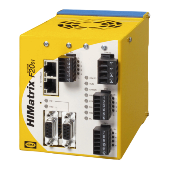
HIMA HIMatrix F20 Safety Manual (72 pages)
Safety-Related Controller
Brand:
HIMA
| Category:
Controller
| Size: 0 MB
Table of Contents
Table of Contents
3
1 Safety Manual
7
Structure and Use of the Document
7
Target Audience
8
Formatting Conventions
8
Safety Notes
8
Operating Tips
9
2 Intended Use
10
Scope
10
De-Energize to Trip Principle/ Energize to Trip Principle
10
Use in Fire Alarm Systems
10
Non-Intended Use
10
Operating Requirements
10
Climatic Requirements
11
Mechanical Requirements
11
Table 2: Standards for EMC, Climatic and Environmental Requirements
11
Table 3: General Requirements
11
Table 4: Climatic Requirements
11
Table 5: Mechanical Tests
11
EMC Requirements
12
Power Supply
12
Table 6: Interference Immunity Tests
12
Table 7: Interference Immunity Tests
12
Table 8: Noise Emission Tests
12
Table 9: Review of the DC Supply Characteristics
12
ESD Protective Measures
13
Requirements to be Met by the Operator and the Machine and System Manufacturers
13
Additional System Documentation
14
Table 10: Himatrix System Documentation
14
3 Safety Concept for Using the PES
15
Safety and Availability
15
Calculating the PFD and the PFH Values
15
Self-Test and Fault Diagnosis
16
Padt
16
Structuring Safety Systems in Accordance with the Energize to Trip Principle
16
Time Parameters Important for Safety
17
Fault Tolerance Time (FTT, See DIN VDE 0801, Appendix A1 2.5.3)
17
Safety Time (of PES)
17
Table 11: Range of Values for the Safety Time
17
Multiple Fault Occurrence Time (MOT)
18
Response Time
18
Processor System Watchdog Time
18
Proof Test
18
Proof Test Execution
18
Frequency of Proof Tests
18
Table 12: Range of Values for the Watchdog Time
18
Safety Requirements
19
Hardware Configuration
19
Programming
19
Communication
20
Maintenance Work
20
Certification
21
TÜV Certificate
21
EU Type Examination
22
4 Central Functions
23
Power Supply Units
23
Functional Description of the Processor System
23
Figure 1: Function Blocks of the F60 CPU
23
Self-Tests
24
Microprocessor Test
24
Memory Areas Test
24
Protected Memory Areas
24
RAM Test
24
Watchdog Test
24
Test of the I/O Bus Inside the Controller
24
Reactions to Processor System Failures
25
Fault Diagnosis
25
5 Inputs
26
General
26
Table 13: Overview of the Himatrix System Inputs
26
Safety of Sensors, Encoders and Transmitters
27
Safety-Related Digital Inputs
27
General
27
Test Routines
27
Reaction in the Event of a Fault
27
Surges on Digital Inputs
27
Table 14: Error Codes with Digital Inputs
27
Configurable Digital Inputs
28
Line Control
28
Figure 2: Line Control
28
Safety-Related Analog Inputs (F35, F3 AIO 8/4 01 and F60)
29
General
29
Table 15: Value of Safety-Related Analog Inputs
29
Table 16: Analog Inputs of the F35 Controller
30
Table 17: Analog Inputs of the F3 AIO 8/4 01 Remote I/O
30
Table 18: Analog Inputs of the F60 Controller
30
Test Routines
31
Reaction in the Event of a Fault
31
Table 19: Configuration of Unused Inputs
31
Table 20: Error Codes with Analog Inputs
31
Safety-Related Counters (F35 and F60)
32
General
32
Reaction in the Event of a Fault
32
Checklist for Safety-Related Inputs
32
Table 21: Error Codes with Counter Inputs
32
6 Outputs
33
General
33
Table 22: Overview of the Himatrix System Outputs
33
Safety of Actuators
34
Safety-Related Digital Outputs
34
Test Routines for Digital Outputs
34
Reaction in the Event of a Fault
34
Behavior in the Event of External Short-Circuit or Overload
34
Line Control
34
Safety-Related Two-Pole Digital Outputs
34
Test Routines for Two-Pole Digital Outputs
35
One-Pole/Two-Pole Connection (F3 DIO 8/8 01, F3 DIO 16/8 01)
35
Reaction in the Event of a Fault
36
Behavior in the Event of External Short-Circuit or Overload
36
Relay Outputs
36
Test Routines for Relay Outputs
36
Reaction in the Event of a Fault
37
Safety-Related Analog Outputs (F60)
37
Test Routines
37
Analog Outputs with Safety-Related Shutdown (F3 AIO 8/4 01)
38
Test Routines
38
Reaction in the Event of a Fault
38
Checklist for Safety-Related Outputs
38
7 Software for Himatrix Systems
39
Safety-Related Aspects of the Operating System
39
Operation and Functions of the Operating System
39
Safety-Related Aspects of Programming
39
Programming Tool's Safety Concept
39
Verifying the Configuration and the User Program
40
Archiving a Project
40
Options for Identifying the Program and the Configuration
41
Resource Parameters
42
Parameters - Versions Beyond 7
42
Table 23: System Parameters of the Resource
43
Table 24: Hardware System Variables
43
Parameters - Versions Prior to 7
44
Protection against Manipulation
44
Table 25: Resource Parameter - Versions Prior to 7
44
Checklist for Creating a User Program
45
8 Safety-Related Aspects of the User Program
46
Scope for Safety-Related Use
46
Programming Basics
46
Functions of the User Program
47
Declaration of Variables and Signals
47
Table 26: Length for the Name of the Variable
47
Acceptance by Test Authority
48
Procedures
48
Assigning Variables to Inputs or Outputs
48
System Parameters of the Resource
49
Table 27: System Parameters of the Resource - Versions Beyond 7
50
Table 28: System Parameters of the CPU
51
Table 29: Hardware System Variables
51
Locking and Unlocking the Controller
52
Table 30: System Variables for Locking and Unlocking the PES
52
Code Generation
53
Loading and Starting the User Program
54
Forcing
54
Forcing - Versions Beyond 7
55
Time Limits
55
Restricting the Use of Forcing
55
Force Editor
56
Forcing Signals - Versions Prior to 7
56
Remote I/O)
56
Table 31: Force Switches and Parameters
56
Online Test
57
Program Documentation for Safety-Related Applications
58
Table 32: CPU Switch Changing the Variables in the OLT Allowed - Version Prior to 7
58
9 Configuring Communication
59
Standard Protocols
59
Safety-Related Protocol (Safeethernet)
59
Receive Timeout
59
Response Time
60
Maximum Cycle Time of the Himatrix Controller
61
Calculating the Worst Case Reaction Time
61
Figure 4: Reaction Time with Interconnection of Two Himatrix Controllers
61
Calculating the Worst Case Reaction Time with Two Remote I/Os
62
Calculating the Worst Case Reaction Time with Two Himatrix and One Himax Controller
62
Figure 5: Reaction Time with Remote I/Os
62
Figure 6: Reaction Time with Two Himatrix Controllers and One Himax Controller
62
Terms
63
Assigning Safeethernet Addresses
63
10 Use in Fire Alarm Systems
64
Figure 7: Wiring of Fire Alarms
64
Figure 8: Example of Open-Circuit and Short-Circuit Monitoring of Digital Outputs
65
Appendix
67
Increasing the SIL of Sensors and Actuators
67
Glossary
68
Index of Figures
69
Index of Tables
70
Index
71
P.O. Box
72
Advertisement
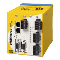
HIMA HIMatrix F20 Manual (56 pages)
Safety-Related Controller
Brand:
HIMA
| Category:
Controller
| Size: 0 MB
Table of Contents
Table of Contents
3
1 Introduction
7
Structure and Use of this Manual
7
Table 1: Himatrix System Variants
7
Target Audience
8
Table 2: Additional Relevant Documents
8
Formatting Conventions
9
Safety Notes
9
Operating Tips
10
2 Safety
11
Intended Use
11
Environmental Requirements
11
ESD Protective Measures
11
Table 3: Environmental Requirements
11
Residual Risk
12
Safety Precautions
12
Emergency Information
12
3 Product Description
13
Safety Function
13
Safety-Related Digital Inputs
13
Figure 1: Connections to Safety-Related Digital Inputs
13
Reaction in the Event of a Fault
14
Line Control
14
Figure 2: Line Control
14
Safety-Related Digital Outputs
15
Figure 3: Connection of Actuators to Outputs
15
Reaction in the Event of a Fault
16
Equipment, Scope of Delivery
17
IP Address and System ID (SRS)
17
Table 4: Part Numbers
17
Type Label
18
Figure 4: Sample Type Label
18
Assembly
19
Figure 5: Front View
19
Figure 6: Block Diagram
19
LED Indicators
20
Operating Voltage LED
20
Table 5: Operating Voltage LED
20
System Leds
21
Table 6: System Leds
21
Communication Leds
22
I/O Leds
22
Fieldbus Leds
22
Table 7: Ethernet Indicators
22
Table 8: I/O Leds
22
Communication
23
Connections for Ethernet Communication
23
Network Ports Used for Ethernet Communication
23
Table 10: Network Ports (UDP Ports) in Use
23
Connections for Fieldbus Communication
24
Pin Assignments
24
Pin Assignment of the D-Sub Connector FB1
24
Table 11: Network Ports (TCP Ports) in Use
24
Table 12: Connections for Fieldbus Communication
24
Table 13: Pin Assignment of D-Sub Connector FB1 for PROFIBUS
24
Pin Assignment of the D-Sub Connector FB1
25
Table 14: Pin Assignment of D-Sub Connector FB1 for Modbus
25
Table 15: Pin Assignment of D-Sub Connector FB1 for RS232
25
Table 16: Pin Assignment of D-Sub Connector FB1 for RS422
25
Pin Assignment of the D-Sub Connector FB1
26
Pin Assignment of the D-Sub Connector FB2
26
Table 17: Pin Assignment of D-Sub Connector FB1 for INTERBUS
26
Table 18: Pin Assignment of D-Sub Connector FB2 for Modbus
26
Reset Key
27
Fan
27
Replacing the Fan
28
Replacement Interval
28
Hardware Clock
28
Figure 8: F20 Cover with Guiding Pins for Fan Plate
28
Table 19: Fan State
28
Product Data
29
Table 20: Product Data
29
Table 21: Specifications for the Digital Inputs and Outputs
30
Table 22: Specifications for the Pulsed Outputs
30
Certified Himatrix F20
31
Table 23: Certificates
31
4 Start-Up
32
Installation and Mounting
32
Connection of the Digital Inputs
32
Surges on Digital Inputs
32
Table 24: Terminal Assignment for the Digital Inputs
32
Connecting the Digital Outputs
33
Connecting Pulsed Outputs
33
Table 25: Terminal Assignment for the Digital Outputs
33
Table 26: Terminal Assignment for the Pulsed Outputs
33
Mounting the F20 in Zone 2
34
Figure 9: Label for Ex Conditions
34
Configuration
35
Configuration with Silworx
35
Parameters and Error Codes for the Inputs and Output
35
Digital Inputs and Outputs for F20
36
Module Tab
36
DIO 8/8: DO Channels Tab
37
Table 27: Silworx - System Parameters for the Digital Inputs, Module Tab
37
Table 28: Silworx - System Parameters for the Digital Inputs, DIO 8/8: DO Channels Tab
37
DIO 8/8: DI Channels Tab
38
Table 29: Silworx - System Parameters for the Digital Inputs, DIO 8/8: DI Channels Tab
38
Pulsed Outputs for F20
39
Module Tab
39
DO 4: Channels Tab
39
Table 30: Silworx - System Parameters for the Pulsed Outputs, Module Tab
39
Table 31: Silworx - System Parameters for the Pulsed Outputs, DO 4: Channels Tab
39
Configuring a Controller Using ELOP II Factory
40
Configuring the Inputs and Outputs
40
Signals and Error Codes for the Inputs and Output
40
Digital Inputs for F20
41
Table 32: ELOP II Factory - Digital Input System Signals
42
Digital Outputs for F20
43
Table 33: ELOP II Factory - Digital Output System Signals
43
Pulsed Outputs for F20
44
Table 34: ELOP II Factory - Pulsed Output System Signals
44
5 Operation
45
Handling
45
Diagnosis
45
6 Maintenance
46
Faults
46
Operating System Version 6.42 and Beyond
46
Operating System Versions Prior to 6.42
46
Maintenance Measures
46
Loading the Operating System
46
Proof Test
46
7 Decommissioning
47
8 Transport
48
9 Disposal
49
Appendix
51
Glossary
51
Index of Figures
52
Index of Tables
53
Index
54
HIMA HIMatrix F20 Engineering Manual (64 pages)
HIMatrix System Automation Devices
Brand:
HIMA
| Category:
Control Unit
| Size: 1 MB
Table of Contents
About this Manual
3
Terminology
5
Table of Contents
8
1 Certification
10
2 Notes for Danger and Use
11
Notes for Danger
11
Notes for Use
11
3 Installation of Himatrix Devices
12
Mechanical
12
Installation of Controllers
12
Installation
12
Cable Routing
12
Air Circulation
14
Assembly Heights
16
Pluggable Cable Dimensions
16
Heat Contemplation
16
Heat Dissipation
17
Definitions
17
Installation Type
17
Internal Convection
17
Temperature State/Operating Temperature
18
Standard
18
Operating Voltage
18
Earth and Shield
19
Earthing the System Voltage 24 VDC
19
Non-Earthed Operation
19
Earthed Operation
19
Earth Connections
19
Shields
19
EMC Protection
20
ESD Protection
20
4 Configuring the Hardware
21
Supply Voltage
21
De-Energize to Trip Mode / Energize to Trip Mode
21
Short-Circuit Characteristics of the Output Channels
22
Using the F35 Controller in the Zone
23
Atex)
23
Use in Central Fire Alarm Systems
24
5 Communication
26
Communication Protocols at Himatrix Systems
26
Field Bus Interfaces of the Controller
27
Ethernet Communication
28
Communication Via Switches
28
Safeethernet
28
Ethernet/Ip
29
TCP S/R (Send/Receive over TCP)
29
Sntp
30
Modbus TCP
30
Operating Parameters of the Ethernet Interfaces
30
Configuration of the Ethernet Interfaces
31
Connections for Safeethernet, Ethernet/Networking Example
33
Field Bus Communication
34
Restrictions for Simultaneous Operation of Protocols
34
Mounting of HIMA Field Bus Communication Modules
35
System Requirements
35
Display of the Actual Versions of the Operating Systems
35
Wiring
36
Safeethernet, Ethernet
36
Interface Elements
37
Specified Cables
37
RJ 45 Connector
38
Switches
40
Field Buses
41
Fundamentals of RS-485 Transfer Mode System
41
Profibus Dp
41
MODBUS Master/Slave Communication
42
Interbus
43
6 Labeling
43
Equipment Identification
43
7 Configuration of the Software
44
Supported Data Types
44
Line Monitoring
44
Required Signals
45
Configuration for Pulsed Outputs
46
Configuration Example
47
Principle Method of Signal Assignment
47
Configuring the Pulsed Outputs and Assignment to the Inputs45
47
Assignment of the Signals to the Inputs and Their Error Codes46
48
Activation of the Pulsed Outputs
48
Line Monitoring at Himatrix F35
48
Line Monitoring at F3 DIO 16/8 01
53
Parameterization of Line Monitoring at 2-Pole Connection
53
Line Monitoring for Lamp Loads and Inductive Loads
55
Line Monitoring with Reduced Voltage for Resistive, Capacitive Loads
56
2-Pole Connection with Common Reference Pole (3-Pole Connection)
56
Table of Configurations for Digital Outputs
57
8 Commissioning, Maintenance, Repairs
58
Testing the Inputs and Outputs for Interference Voltage and Earth Faults
58
Modifications
58
Replacement of Modules
59
Maintenance
59
Replacement of Back-Up Batteries
59
Repair of Controllers and Modules
60
Supply of Internal Documentation
60
9 Operating Conditions
61
Climatic Conditions
61
Mechanical Conditions
62
EMC Conditions
62
Voltage Supply
63
Advertisement
Advertisement
Related Products
HIMA HIMatrix F60
HIMA HIMatrix F2 DO 16 01
HIMA HIMatrix F1 DI 16 01
HIMA HIMatrix F3 DIO 20/8 02
HIMA HIMatrix F30
HIMA HIMatrix F3
HIMA HIMatrix F35
HIMA HIMatrix F60 DI 32 01
HIMA HIMatrix F2 DO 8 01
HIMA HIMatrix F3 DIO 8/8 01
HIMA Categories
Controller
Control Unit
I/O Systems
Industrial Equipment
Relays
More HIMA Manuals
Login
Sign In
OR
Sign in with Facebook
Sign in with Google
Upload manual
Upload from disk
Upload from URL