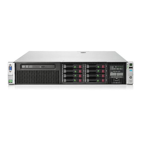
HP ProLiant DL385p Maintenance And Service Manual
Gen8
Hide thumbs
Also See for ProLiant DL385p:
- Reference manual (112 pages) ,
- User manual (140 pages) ,
- Specification (60 pages)
Table of Contents
Advertisement
Quick Links
HPE ProLiant DL385p Gen8 Server
Maintenance and Service Guide
Abstract
This guide describes identification and maintenance procedures, diagnostic tools, specifications, and requirements for hardware
components and software. This guide is for an experienced service technician. Hewlett Packard Enterprise assumes you are qualified in the
servicing of computer equipment, trained in recognizing hazards in products, and are familiar with weight and stability precautions.
Part Number: 661849-003R
November 2015
Edition: 4
Advertisement
Table of Contents

Related Manuals for HP ProLiant DL385p


Summary of Contents for HP ProLiant DL385p
- Page 1 HPE ProLiant DL385p Gen8 Server Maintenance and Service Guide Abstract This guide describes identification and maintenance procedures, diagnostic tools, specifications, and requirements for hardware components and software. This guide is for an experienced service technician. Hewlett Packard Enterprise assumes you are qualified in the servicing of computer equipment, trained in recognizing hazards in products, and are familiar with weight and stability precautions.
- Page 2 © Copyright 2012, 2015 Hewlett Packard Enterprise Development LP The information contained herein is subject to change without notice. The only warranties for Hewlett Packard Enterprise products and services are set forth in the express warranty statements accompanying such products and services. Nothing herein should be construed as constituting an additional warranty.
-
Page 3: Table Of Contents
Full length expansion board ........................53 Heatsink ................................. 54 Processor ................................56 DIMMs ..................................61 System battery ............................... 62 System board ................................. 63 150W PCIe power cable option ..........................69 Chipset SATA cable option ............................ 70 HP Trusted Platform Module ..........................71 Contents 3... - Page 4 Troubleshooting ........................... 72 Troubleshooting resources ............................. 72 HPE Insight Diagnostics ............................72 HPE Insight Diagnostics survey functionality ....................72 HPE ROM-Based Setup Utility ..........................73 Integrated Management Log ..........................73 USB support and functionality ..........................73 USB support ..............................73 Internal USB functionality ..........................
-
Page 5: Customer Self Repair
Customer self repair Hewlett Packard Enterprise products are designed with many Customer Self Repair (CSR) parts to minimize repair time and allow for greater flexibility in performing defective parts replacement. If during the diagnosis period Hewlett Packard Enterprise (or Hewlett Packard Enterprise service providers or service partners) identifies that the repair can be accomplished by the use of a CSR part, Hewlett Packard Enterprise will ship that part directly to you for replacement. - Page 6 • Obligatoire—Pièces pour lesquelles la réparation par le client est obligatoire. Si vous demandez à Hewlett Packard Enterprise de remplacer ces pièces, les coûts de déplacement et main d'œuvre du service vous seront facturés. • Facultatif—Pièces pour lesquelles la réparation par le client est facultative. Ces pièces sont également conçues pour permettre au client d'effectuer lui-même la réparation.
- Page 7 NOTA: alcuni componenti Hewlett Packard Enterprise non sono progettati per la riparazione da parte del cliente. Per rispettare la garanzia, Hewlett Packard Enterprise richiede che queste parti siano sostituite da un centro di assistenza autorizzato. Tali parti sono identificate da un "No" nel Catalogo illustrato dei componenti.
- Page 8 Support Center anrufen und sich von einem Mitarbeiter per Telefon helfen lassen. Den Materialien von Hewlett Packard Enterprise, die mit einem CSR-Ersatzteil geliefert werden, können Sie entnehmen, ob das defekte Teil an Hewlett Packard Enterprise zurückgeschickt werden muss. Wenn es erforderlich ist, das defekte Teil an Hewlett Packard Enterprise zurückzuschicken, müssen Sie dies innerhalb eines vorgegebenen Zeitraums tun, in der Regel innerhalb von fünf (5) Geschäftstagen.
- Page 9 deberá hacerlo en el periodo de tiempo especificado, normalmente cinco días laborables. Los componentes defectuosos deberán devolverse con toda la documentación relacionada y con el embalaje de envío. Si no enviara el componente defectuoso requerido, Hewlett Packard Enterprise podrá cobrarle por el de sustitución.
- Page 10 Enterprise u voor het vervangende onderdeel kosten in rekening brengen. Bij reparatie door de klant betaalt Hewlett Packard Enterprise alle verzendkosten voor het vervangende en geretourneerde onderdeel en kiest Hewlett Packard Enterprise zelf welke koerier/transportonderneming hiervoor wordt gebruikt. Neem contact op met een Service Partner voor meer informatie over het Customer Self Repair programma van Hewlett Packard Enterprise.
- Page 11 Para obter mais informações sobre o programa de reparo feito pelo cliente da Hewlett Packard Enterprise, entre em contato com o fornecedor de serviços local. Para o programa norte-americano, visite o site da Hewlett Packard Enterprise (http://www.hpe.com/support/selfrepair). Serviço de garantia apenas para peças A garantia limitada da Hewlett Packard Enterprise pode incluir um serviço de garantia apenas para peças.
- Page 12 Customer self repair 12...
- Page 13 Customer self repair 13...
- Page 14 Customer self repair 14...
-
Page 15: Illustrated Parts Catalog
Illustrated parts catalog Mechanical components Item Description Spare part number Customer self repair (on page 5) Access panel — — a) Access panel, 8 drive SFF, 8 drive LFF 691272-001 Mandatory b) Access panel, 25 drive SFF, 12 drive LFF* 691273-001 Mandatory Fan cage 662518-001... - Page 16 Item Description Spare part number Customer self repair (on page 5) 8 drive SFF front end — — a) 8 drive SFF front end, with cables, left and 696955-001 Optional right ears (no backplane) b) 8 drive SFF backplane, with cables 670943-001 Optional 8 drive LFF front end, with cables, left and...
- Page 17 Mandatory—Parts for which customer self repair is mandatory. If you request Hewlett Packard Enterprise to replace these parts, you will be charged for the travel and labor costs of this service. Optional—Parts for which customer self repair is optional. These parts are also designed for customer self repair. If, however, you require that Hewlett Packard Enterprise replace them for you, there may or may not be additional charges, depending on the type of warranty service designated for your product.
- Page 18 Obrigatório—Peças cujo reparo feito pelo cliente é obrigatório. Se desejar que a Hewlett Packard Enterprise substitua essas peças, serão cobradas as despesas de transporte e mão-de-obra do serviço. Opcional—Peças cujo reparo feito pelo cliente é opcional. Essas peças também são projetadas para o reparo feito pelo cliente.
-
Page 19: System Components
System components Item Description Spare part Customer self repair number (on page 5) System components — — Hot-plug fan 662520-001 Mandatory Power supplies, hot-plug — — a) 460 W, 92% 511777-001 Mandatory Mandatory b) 460 W, Platinum Plus, 94%* 660184-001 c) 750 W, 92%* 511778-001 Mandatory... - Page 20 Item Description Spare part Customer self repair number (on page 5) Mandatory b) 10GbE 2-port, 530FLR Adapter FIO Kit* 649869-001 c) Ff 10Gb 2-port, 554FLR-SFP+ Adapter FIO Kit* 634026-001 Mandatory d) InfiniBand FDR/EN 10/40Gb 2-port, 544FLR-QSFP 656090-001 Mandatory Adapter* e) InfiniBand QDR/EN 10Gb 2-port, 544FLR-QSFP 656091-001 Mandatory Adapter*...
- Page 21 Item Description Spare part Customer self repair number (on page 5) Optional o) 2.80-GHz AMD Opteron processor 6348, 12c, 705220-001 115W* p) 2.80-GHz AMD Opteron processor 6386SE, 16c, 705216-001 Optional 140W* q) 3.00-GHz AMD Opteron processor 6220, 115W* 662839-001 Optional r) 3.20-GHz AMD Opteron processor 6328, 8c, 115W* 705222-001 Optional s) 3.30-GHz AMD Opteron processor 6204, 115W*...
- Page 22 Item Description Spare part Customer self repair number (on page 5) Mandatory e) 200-GB, LFF, MLC, 3G 653969-001 f) 400-GB, LFF, MLC, 3G 653970-001 Mandatory Hot-plug solid state SAS* — — a) 200-GB, SFF, SLC 653961-001 Mandatory Mandatory b) 200-GB, SFF, SC, MLC 691025-001 c) 400-GB, SFF, SLC 653962-001...
- Page 23 *Not shown **All processors in this HPE ProLiant server must have the same cache size, speed, number of cores, and rated maximum power consumption. Mandatory—Parts for which customer self repair is mandatory. If you request Hewlett Packard Enterprise to replace these parts, you will be charged for the travel and labor costs of this service.
- Page 24 Geen—Sommige onderdelen van Hewlett Packard Enterprise zijn niet ontworpen om door de klant zelf te worden vervangen. Om te voldoen aan de garantievoorwaarden eist Hewlett Packard Enterprise dat een geautoriseerde serviceverlener het onderdeel vervangt. Deze onderdelen worden aangeduid met 'Geen' in de geïllustreerde onderdelencatalogus.
-
Page 25: Removal And Replacement Procedures
Removal and replacement procedures Required tools You need the following item for some procedures: • T-10/T-15 Torx screwdriver • HPE Insight Diagnostics software ("HPE Insight Diagnostics" on page 72) Preparation procedures To access some components and perform certain service procedures, you must perform one or more of the following procedures: •... -
Page 26: Extend The Server From The Rack
This method forces the server to enter standby mode without properly exiting applications and the OS. If an application stops responding, you can use this method to force a shutdown. • Use a virtual power button selection through iLO. This method initiates a controlled remote shutdown of applications and the OS before the server enters standby mode. -
Page 27: Remove The Server From The Rack
Remove the server from the rack To remove the server from a Hewlett Packard Enterprise, Compaq branded, Telco, or third-party rack: Power down the server (on page 25). Extend the server from the rack (on page 26). Disconnect the cabling and remove the server from the rack. For more information, refer to the documentation that ships with the rack mounting option. -
Page 28: Access The Product Rear Panel
Access the product rear panel Opening the cable management arm IMPORTANT: The cable management arm is not supported with the friction rail kit. To access the server rear panel: Release the cable management arm. Open the cable management arm. Note that the cable management arm can be right-mounted or left-mounted. -
Page 29: Safety Considerations
Power down the server (on page 25). Remove all power: Disconnect each power cord from the power source. Disconnect each power cord from the server. Extend ("Extend the server from the rack" on page 26) or remove ("Remove the server from the rack"... -
Page 30: Server Warnings And Cautions
This symbol indicates the presence of a hot surface or hot component. If this surface is contacted, the potential for injury exists. WARNING: To reduce the risk of injury from a hot component, allow the surface to cool before touching. This symbol indicates that the component exceeds the recommended weight for one individual to handle safely. -
Page 31: Remove The Air Baffle
To replace the component, reverse the removal procedure. Remove the air baffle CAUTION: For proper cooling, do not operate the server without the access panel, baffles, expansion slot covers, or blanks installed. If the server supports hot-plug components, minimize the amount of time the access panel is open. To remove the component: Power down the server (on page 25). -
Page 32: 2U Rack Bezel
2U rack bezel To remove the component: To replace the component, reverse the removal procedure. PCIe riser blank CAUTION: To prevent improper cooling and thermal damage, do not operate the server unless all PCI slots have either an expansion slot cover or an expansion board installed. To remove the component: Power down the server (on page 25). -
Page 33: Remove The Primary Pcie Riser Cage
Remove the PCIe riser blank. To replace the component, reverse the removal procedure. Remove the primary PCIe riser cage CAUTION: To prevent damage to the server or expansion boards, power down the server and remove all AC power cords before removing or installing the PCIe riser cage. Power down the server (on page 25). -
Page 34: Remove The Secondary Pcie Riser Cage
Remove the PCIe riser cage. To install the component, reverse the removal procedure. Remove the secondary PCIe riser cage CAUTION: To prevent damage to the server or expansion boards, power down the server and remove all AC power cords before removing or installing the PCIe riser cage. To remove the component: Power down the server (on page 25). -
Page 35: Pcie Riser Board
If a full-length expansion board is installed in slot 4, release the full-length expansion board retainer, and then remove the PCIe riser cage. To install the component, reverse the removal procedure. PCIe riser board To remove the component: Power down the server (on page 25). Remove all power: Disconnect each power cord from the power source. -
Page 36: Drive Blank
Remove the PCIe riser board. To replace the component, reverse the removal procedure. Drive blank CAUTION: To prevent improper cooling and thermal damage, do not operate the server unless all bays are populated with either a component or a blank. Remove the drive blank. -
Page 37: Power Supply Blank
Remove the drive. To replace the component, reverse the removal procedure. Power supply blank Remove the blank. To replace the component, reverse the removal procedure. AC power supply CAUTION: To prevent improper cooling and thermal damage, do not operate the server unless all bays are populated with either a component or a blank. -
Page 38: Optical Drive
To replace the component, reverse the removal procedure. Optical drive To remove the component: Power down the server (on page 25). Remove all power: Disconnect each power cord from the power source. Disconnect each power cord from the server. Extend ("Extend the server from the rack"... -
Page 39: Power Supply Backplane
Remove the optical drive. To replace the component, reverse the removal procedure. Power supply backplane To remove the component: Power down the server (on page 25). Remove all power: Disconnect each power cord from the power source. Disconnect each power cord from the server. Remove all power supplies ("AC power supply"... -
Page 40: Hot-Plug Fan
Disconnect the SATA cable. Remove the power supply backplane. To replace the component, reverse the removal procedure. Hot-plug fan The server supports variable fan speeds. The fans operate at minimum speed until a temperature change requires a fan speed increase to cool the server. The server shuts down in the following temperature-related scenarios: •... -
Page 41: Fan Cage
IMPORTANT: An immediate shutdown is a hardware-controlled function and it overrides any firmware or software actions. • In the operating system: The Health Driver performs an orderly shutdown if it detects a cautionary temperature level. If the server detects a critical temperature level before the orderly shutdown occurs, the server performs an immediate shutdown. -
Page 42: Flexiblelom
Disconnect each power cord from the power source. Disconnect each power cord from the server. Extend ("Extend the server from the rack" on page 26) or remove ("Remove the server from the rack" on page 27) the server from the rack. Remove the access panel ("Access panel"... - Page 43 Loosen the thumbscrew. Remove the existing FlexibleLOM. Pull the FlexibleLOM toward the front of the server while removing it, to avoid catching it on the rear chassis. To replace the component: Firmly seat the FlexibleLOM in the slot, and then tighten the thumbscrew. Install the PCIe riser cage ("Remove the primary PCIe riser cage"...
-
Page 44: Sff Hard Drive Cage
SFF hard drive cage To remove the component: Power down the server (on page 25). Remove all power: Disconnect each power cord from the power source. Disconnect each power cord from the server. Extend ("Extend the server from the rack" on page 26) or remove ("Remove the server from the rack"... -
Page 45: Front Panel Assembly
Remove the Systems Insight Display: Remove the screw from the rear of the Systems Insight Display. Disconnect the Systems Insight Display cable and the USB cable from the system board, and disconnect the USB cable from the front of the Systems Insight Display. Remove the Systems Insight Display. -
Page 46: Flash-Backed Write Cache Procedures
Remove the serial label pull tab, and retain it for the new front panel assembly. Remove the air baffle (on page 31). Remove all drives ("Hot-plug drive" on page 36). If installed, remove the optical drive ("Optical drive" on page 38). Remove the fan cage ("Fan cage"... -
Page 47: Flash-Backed Write Cache Module
• Removal and replacement of failed components: Removing the cache module ("Flash-backed write cache module" on page 47) Removing the capacitor pack ("Flash-backed write cache capacitor pack" on page 48) • Recovery of cached data from a failed server ("Recovering data from the flash-backed write cache"... -
Page 48: Flash-Backed Write Cache Capacitor Pack
Open the ejector latches on each side of the cache module connector. Normally, the cache module is ejected from the cache module connector. If the module is not ejected automatically, remove the cache module. If the cache module is connected to a capacitor pack, disconnect the capacitor pack cable from the connector on the top of the cache module. - Page 49 Power down the server (on page 25). Remove all power: Disconnect each power cord from the power source. Disconnect each power cord from the server. CAUTION: In systems that use external data storage, be sure that the server is the first unit to be powered down and the last to be powered back up.
- Page 50 8 or 16 SFF configuration 8 LFF configuration Removal and replacement procedures 50...
-
Page 51: Recovering Data From The Flash-Backed Write Cache
12 LFF or 25 SFF configuration To replace the component, reverse the removal procedure. Recovering data from the flash-backed write cache If the server fails, use the following procedure to recover data temporarily stored in the FBWC. CAUTION: Before starting this procedure, read the information about protecting against electrostatic discharge. -
Page 52: Expansion Slot Blanks
Expansion slot blanks WARNING: To reduce the risk of personal injury, electric shock, or damage to the equipment, remove the power cord to remove power from the server. The front panel Power On/Standby button does not completely shut off system power. Portions of the power supply and some internal circuitry remain active until AC power is removed. -
Page 53: Full Length Expansion Board
WARNING: To reduce the risk of personal injury, electric shock, or damage to the equipment, remove the power cord to remove power from the server. The front panel Power On/Standby button does not completely shut off system power. Portions of the power supply and some internal circuitry remain active until AC power is removed. -
Page 54: Heatsink
Extend ("Extend the server from the rack" on page 26) or remove ("Remove the server from the rack" on page 27) the server from the rack. Remove the access panel ("Access panel" on page 30). Disconnect any external cables that are connected to the expansion board. Disconnect any internal cables that are connected to the expansion board. - Page 55 WARNING: To reduce the risk of personal injury from hot surfaces, allow the drives and the internal system components to cool before touching them. CAUTION: The heatsink thermal interface media is not reusable and must be replaced if the heatsink is removed from the processor after it has been installed. CAUTION: To avoid thermal shutdown, all fans must be installed in a dual processor configuration.
-
Page 56: Processor
To replace the component: Remove the thermal interface protective cover from the heatsink. Install the heatsink. Install the air baffle ("Remove the air baffle" on page 31). Install the access panel ("Access panel" on page 30). Slide the server into the rack. Connect each power cord to the server. - Page 57 CAUTION: To avoid damage to the processor and system board, only authorized personnel should attempt to replace or install the processor in this server. CAUTION: To prevent possible server malfunction and damage to the equipment, multiprocessor configurations must contain processors with the same part number. To remove a processor: Power down the server (on page 25).
- Page 58 Using the processor tool, remove the processor from the system board. CAUTION: To avoid damage to the processor, do not touch the bottom of the processor, especially the contact area. To replace a processor: IMPORTANT: Be sure the processor remains inside the processor installation tool. If the processor has separated from the installation tool, carefully re-insert the processor in the tool.
- Page 59 The processor fits one way into the socket. Use the alignment guides on the processor and socket to properly align the processor with the socket. Install the spare processor. THE PINS ON THE SYSTEM BOARD ARE VERY FRAGILE AND EASILY DAMAGED. CAUTION: THE PINS ON THE SYSTEM BOARD ARE VERY FRAGILE AND EASILY DAMAGED.
- Page 60 Clean the old thermal grease from the heatsink with the alcohol swab. Allow the alcohol to evaporate before continuing. Apply all the grease to the top of the processor in one of the following patterns to ensure even distribution. Removal and replacement procedures 60...
-
Page 61: Dimms
Install the heatsink. Install the air baffle. Install the access panel ("Access panel" on page 30). Install the server into the rack. Connect each power cord to the server. Connect each power cord to the power source. Power up the server. DIMMs IMPORTANT: This server does not support mixing RDIMMs and UDIMMs. -
Page 62: System Battery
Remove the DIMM. To replace the component, reverse the removal procedure. For DIMM configuration information, see the server user guide. System battery If the server no longer automatically displays the correct date and time, you may need to replace the battery that provides power to the real-time clock. -
Page 63: System Board
Remove the battery. To replace the component, reverse the removal procedure. For more information about battery replacement or proper disposal, contact an authorized reseller or an authorized service provider. System board To remove the component: Power down the server (on page 25). Remove all power: Disconnect each power cord from the power source. - Page 64 Remove left and right fan cage brackets. Loosen the system board thumbscrews. Remove the system board, using the handle to lift it out of the chassis. Removal and replacement procedures 64...
- Page 65 To replace the component: Install the spare system board. Prepare the processor socket on the spare system board. Remove the processor socket protective cover. Removal and replacement procedures 65...
- Page 66 Open the processor retaining latch and the processor socket retaining bracket. Install the processor socket cover onto the processor socket of the failed system board. Install the processor on the spare system board. IMPORTANT: Be sure the processor remains inside the processor installation tool. If the processor has separated from the installation tool, carefully re-insert the processor in the tool.
- Page 67 The processor fits one way into the socket. Use the alignment guides on the processor and socket to properly align the processor with the socket. Install the spare processor. THE PINS ON THE SYSTEM BOARD ARE VERY FRAGILE AND EASILY DAMAGED. CAUTION: THE PINS ON THE SYSTEM BOARD ARE VERY FRAGILE AND EASILY DAMAGED.
- Page 68 Clean the old thermal grease from the heatsink with the alcohol swab. Allow the alcohol to evaporate before continuing. Apply all the grease to the top of the processor in one of the following patterns to ensure even distribution. Removal and replacement procedures 68...
-
Page 69: 150W Pcie Power Cable Option
Install the heatsink. IMPORTANT: Install all components with the same configuration that was used on the failed system board. Install all components removed from the failed system board. Install the access panel ("Access panel" on page 30). Install the power supplies ("AC power supply"... -
Page 70: Chipset Sata Cable Option
WARNING: To reduce the risk of personal injury, electric shock, or damage to the equipment, remove the power cord to remove power from the server. The front panel Power On/Standby button does not completely shut off system power. Portions of the power supply and some internal circuitry remain active until AC power is removed. -
Page 71: Hp Trusted Platform Module
Disconnect the Chipset SATA cable from the system board and the hard drive backplane and remove from the cable guide. To replace the component, reverse the removal procedure. HP Trusted Platform Module The TPM is not a customer-removable part. CAUTION: Any attempt to remove an installed TPM from the system board breaks or disfigures the TPM security rivet. -
Page 72: Troubleshooting
Troubleshooting Troubleshooting resources The ProLiant Gen8 Troubleshooting Guide, Volume I: Troubleshooting provides procedures for resolving common problems and comprehensive courses of action for fault isolation and identification, issue resolution, and software maintenance on ProLiant servers and server blades. To view the guide, select a language: •... -
Page 73: Hpe Rom-Based Setup Utility
This functionality supports operating systems that may not be supported by the server. For operating systems supported by the server, see the Hewlett Packard Enterprise website (http://www.hpe.com/info/supportos). If a significant change occurs between data-gathering intervals, the survey function marks the previous information and overwrites the survey data files to reflect the latest changes in the configuration. -
Page 74: Internal Usb Functionality
Legacy USB support provides USB functionality in environments where USB support is not available normally. Specifically, Hewlett Packard Enterprise provides legacy USB functionality for the following: • POST • RBSU • Diagnostics • • Operating environments which do not provide native USB support Internal USB functionality An internal USB connector is available for use with security key devices and USB drive keys. -
Page 75: Component Identification
Component identification Front panel components • 8 drive SFF configuration Item Description Video connector Quick release levers (2) SATA optical drive bay SFF drive bays Serial number label USB connectors (2) Systems Insight Display • 16 drive SFF configuration (with optional drive cage) Item Description Video connector... - Page 76 Item Description Systems Insight Display USB connectors (2) • 25 SFF drive configuration Item Description Video connector Quick release levers (2) Drive bays USB connector • 8 drive LFF configuration Item Description Video connector Quick release levers (2) Drive bays Systems Insight Display USB connector Component identification 76...
-
Page 77: Front Panel Leds And Buttons
• 12 drive LFF configuration Item Description Video connector Quick release levers (2) Drive bays USB connector Front panel LEDs and buttons • Component identification 77... - Page 78 • Item Description Status NIC status LED Solid green = Link to network Flashing green (1 Hz/cycle per sec) = Network active Off = No network activity Health LED Solid green = Normal Flashing amber = System degraded Flashing red (1 Hz/cycle per sec) = System critical Fast-flashing red (4 Hz/cycles per sec) = Power fault* Power On/Standby button Solid green = System on...
-
Page 79: Systems Insight Display Leds
Systems Insight Display LEDs The Systems Insight Display LEDs represent the system board layout. The display, available on 8 SFF, 16 SFF, and 8 LFF configurations, enables diagnosis with the access panel installed. Item Description Status Power cap Off = System is in standby, or no cap is set. -
Page 80: Systems Insight Display Led Combinations
Systems Insight Display LED combinations When the health LED on the front panel illuminates either amber or red, the server is experiencing a health event. Combinations of illuminated Systems Insight Display LEDs, the system power LED, and the health LED indicate system status. Systems Insight Health LED System power... -
Page 81: Rear Panel Components
Rear panel components Item Description PCIe slots 1–3 (top to bottom) PCIe slots 4–6, optional (top to bottom) Power supply 1 (PS1) PS1 power connector PS2 power connector, optional Power supply 2 (PS2), optional USB connectors (4) Video connector iLO connector Serial connector FlexibleLOM ports (Shown: 4x1Gb/Optional: 2x10Gb);... -
Page 82: Non-Hot-Plug Pcie Riser Board Slot Definitions
Item Description Status Power supply 1 Off = System is off or power supply has failed. Solid green = Normal NIC activity LED Off = No network activity Solid green = Link to network Flashing green = Network activity NIC link LED Off = No network link Green = Network link Non-hot-plug PCIe riser board slot definitions... -
Page 83: System Board Components
System board components Item Description Fan connector 6 Systems Insight Display connector Fan connector 5 Processor 1 DIMM slots Fan connector 4 Front I/O connector Front USB connector Fan connector 3 First drive cage Fan connector 2 Processor 2 DIMM slots Second drive cage Fan connector 1 NMI jumper... -
Page 84: System Maintenance Switch
Item Description System battery TPM connector Primary (processor 1) PCIe riser connector Processor 1 socket FlexibleLOM SAS port 1i SAS port 2i SAS cache module connector System maintenance switch Position Default Function Off = iLO security is enabled. On = iLO security is disabled. Off = System configuration can be changed. -
Page 85: Dimm Slot Locations
For more information, see the Hewlett Packard Enterprise website (http://www.hpe.com/support/NMI). DIMM slot locations DIMM slots are numbered sequentially (1 through 12) for each processor. The supported AMP modes use the letter assignments for population guidelines. SAS and SATA device numbers •... -
Page 86: Hot-Plug Drive Led Definitions
• 25 SFF device bay numbering • 8 LFF device bay numbering • 12 LFF device bay numbering Hot-plug drive LED definitions Item Status Definition The drive is being identified by a host application. Locate Solid blue Flashing blue The drive carrier firmware is being updated or requires an update. -
Page 87: Pcie Riser Cage Led
Item Status Definition No drive activity Do not remove Solid white Do not remove the drive. Removing the drive causes one or more of the logical drives to fail. Removing the drive does not cause a logical drive to fail. Drive status Solid green The drive is a member of one or more logical drives. -
Page 88: Fbwc Module Leds (P222, P420, P421)
Status Off = AC power is disconnected. Missing = Riser cage is not installed, or power might not be connected. FBWC module LEDs (P222, P420, P421) The FBWC module has three single-color LEDs (one amber and two green). The LEDs are duplicated on the reverse side of the cache module to facilitate status viewing. -
Page 89: Hot-Plug Fans
Hot-plug fans CAUTION: To avoid damage to server components, fan blanks must be installed in fan bays 1 and 2 in a single-processor configuration. The only two valid fan configurations are listed in the following table. Configuration Fan bay 1 Fan bay 2 Fan bay 3 Fan bay 4 Fan bay 5 Fan bay 6 Fan blank Fan blank... -
Page 90: Cabling
Cabling SAS hard drive cabling • SFF hard drive cabling • SFF cabling, with optional drive cage Cabling 90... -
Page 91: Optical Drive Cabling
• LFF hard drive cabling Optical drive cabling Cabling 91... -
Page 92: Fbwc Cabling
FBWC cabling • 8 or 16 drive SFF • 8 drive LFF Cabling 92... - Page 93 • 12 LFF or 25 SFF • PCIe option Depending on the server configuration, you may need to remove the primary PCIe riser cage (on page 33) before cabling to a PCIe expansion board. Cabling 93...
-
Page 94: Specifications
Specifications Environmental specifications Specification Value Temperature range* 10°C to 35°C (50°F to 95°F) Operating -30°C to 50°C (-22°F to 122°F) Shipping -30°C to 60°C (-22°F to 140°F) Storage 28°C (82.4°F) Maximum wet bulb temperature Relative humidity (noncondensing)** 10% to 90% Operating 5% to 95% Non-operating... -
Page 95: Cs Gold Power Supply (92% Efficiency)
For detailed power supply specifications, see the quickspecs on the Hewlett Packard Enterprise website (http://www.hpe.com/info/Quickspecs-Moonshot-1500Chassis). 460 W CS Gold power supply (92% efficiency) Specification Value Input requirements — 100V to 240V AC Rated input voltage 50 Hz or 60 Hz Rated input frequency 5.5A to 2.2A Rated input current... -
Page 96: Cs Platinum Plus Power Supply (94% Efficiency)
750 W at 100 V to 120 V AC input Rated steady-state power 750 W at 200 V to 240 V AC input 750 W at 100 V to 120 V AC input Maximum peak power 750 W at 200 V to 240 V AC input 750 W CS Platinum Plus power supply (94% efficiency) Specification Value... -
Page 97: 1200 W Cs Platinum Plus Power Supply (90% Efficiency)
supply circuit and the earthing conductor, and also the point of earthing of the DC system. The DC system must be earthed elsewhere. • The DC supply source is to be located within the same premises as the equipment. • Switching or disconnecting devices must not be in the earthed circuit conductor between the DC source and the point of connection of the earthing electrode conductor. -
Page 98: Acronyms And Abbreviations
Acronyms and abbreviations FBWC flash-backed write cache Integrated Lights-Out Integrated Management Log nonmaskable interrupt NVRAM nonvolatile memory PCIe Peripheral Component Interconnect Express POST Power-On Self Test RBSU ROM-Based Setup Utility serial attached SCSI SATA serial ATA semi-rigid straight (connector) Trusted Platform Module Acronyms and abbreviations 98... - Page 99 unit identification universal serial bus Acronyms and abbreviations 99...
-
Page 100: Documentation Feedback
Documentation feedback Hewlett Packard Enterprise is committed to providing documentation that meets your needs. To help us improve the documentation, send any errors, suggestions, or comments to Documentation Feedback (mailto:docsfeedback@hpe.com). When submitting your feedback, include the document title, part number, edition, and publication date located on the front cover of the document. For online help content, include the product name, product version, help edition, and publication date located on the legal notices page. -
Page 101: Index
Index 150W PCIe power cable 69 fan cage 41 fans 40 FBWC cabling 92 FBWC module 88 AC power supply 37, 95, 96, 97 features 75 access panel 30 flash-backed write cache capacitor pack 48 air baffle 31 flash-backed write cache module 47 flash-backed write cache procedures 46, 51 FlexibleLOM 42 front panel assembly 45... - Page 102 Systems Insight Display 27, 44, 75, 79, 80 Systems Insight Display LEDs 79, 80 NIC connectors 81 technical support 5 operating system crash 84 tools 25 optical drive 38, 75 TPM (Trusted Platform Module) 71 optical drive cable 91 TPM connector 83 troubleshooting 72 part numbers 15 PCI expansion slot definitions 82...
Need help?
Do you have a question about the ProLiant DL385p and is the answer not in the manual?
Questions and answers