HP ProLiant DL385p User Manual
Hp proliant dl385p gen8 server user guide
Hide thumbs
Also See for ProLiant DL385p:
- Reference manual (112 pages) ,
- Specification (60 pages) ,
- Maintenance and service manual (102 pages)
Table of Contents
Advertisement
Quick Links
HP ProLiant DL385p Gen8 Server
User Guide
Abstract
This document is for the person who installs, administers, and troubleshoots servers and storage systems. HP assumes you are qualified in the
servicing of computer equipment and trained in recognizing hazards in products with hazardous energy levels.
Part Number: 661850-001
June 2012
Edition: 1
Advertisement
Table of Contents

Subscribe to Our Youtube Channel
Related Manuals for HP ProLiant DL385p


Summary of Contents for HP ProLiant DL385p
-
Page 1: User Guide
HP ProLiant DL385p Gen8 Server User Guide Abstract This document is for the person who installs, administers, and troubleshoots servers and storage systems. HP assumes you are qualified in the servicing of computer equipment and trained in recognizing hazards in products with hazardous energy levels. - Page 2 Nothing herein should be construed as constituting an additional warranty. HP shall not be liable for technical or editorial errors or omissions contained herein. Microsoft®, Windows®, and Windows Server® are U.S. registered trademarks of Microsoft Corporation. Bluetooth® is a trademark owned by its proprietor and used by Hewlett-Packard Company under license.
-
Page 3: Table Of Contents
Contents Component identification ....................... 7 Front panel components ..........................7 Front panel LEDs and buttons ........................9 Access the Systems Insight Display ......................10 Systems Insight Display LEDs ........................11 Systems Insight Display LED combinations ....................12 Rear panel components ..........................13 Rear panel LEDs and buttons ........................ - Page 4 Rack warnings ............................39 Identifying the contents of the server shipping carton ..................40 Installing hardware options ........................40 Installing the server into the rack ........................ 40 Installing the operating system........................42 Powering on and selecting boot options ..................... 42 Registering the server ..........................
- Page 5 Scripting Toolkit .......................... 102 HP Service Pack for ProLiant ........................103 HP Smart Update Manager ......................103 HP ROM-Based Setup Utility ........................103 Using RBSU ..........................104 Auto-configuration process ......................104 Boot options ..........................105 Configuring AMP modes ......................105 Re-entering the server serial number and product ID .................
- Page 6 Environmental specifications ........................121 Mechanical specifications ........................121 Power supply specifications ........................121 HP 460 W CS Gold power supply (92% efficiency) ................. 122 HP 460 W CS Platinum Plus power supply (94% efficiency) .............. 122 HP 750 W CS Gold power supply (92% efficiency) ................. 123 HP 750 W CS Platinum Plus power supply (94% efficiency) ..............
-
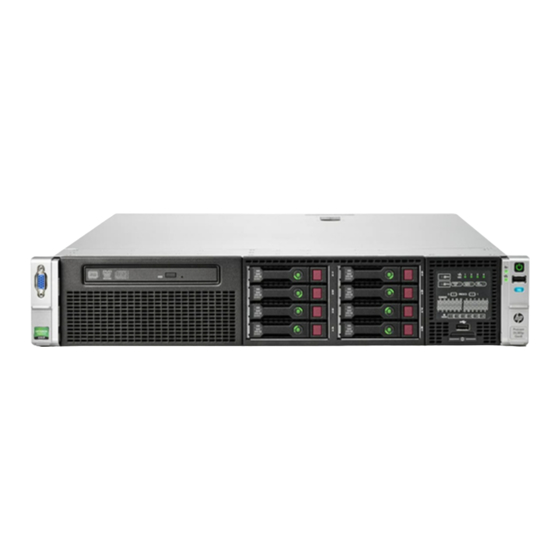
Page 7: Component Identification
Component identification Front panel components • 8 drive SFF configuration Item Description Video connector Quick release levers (2) SATA optical drive bay SFF drive bays Serial number label USB connectors (2) Systems Insight Display • 16 drive SFF configuration (with optional drive cage) Item Description Video connector... - Page 8 Item Description Drive bays (box 1) Drive bays (box 2) Systems Insight Display USB connectors (2) • 25 SFF drive configuration Item Description Video connector Quick release levers (2) Drive bays USB connector • 8 drive LFF configuration Item Description Video connector Quick release levers (2) Drive bays...
-
Page 9: Front Panel Leds And Buttons
• 12 drive LFF configuration Item Description Video connector Quick release levers (2) Drive bays USB connector Front panel LEDs and buttons • Component identification 9... -
Page 10: Access The Systems Insight Display
• Item Description Status NIC status LED Off = No network link Solid green = Link to network Flashing green = Network activity Health LED Solid Green = Normal Flashing Amber = System degraded Flashing Red = System critical To identify components in degraded or critical state, see "Systems Insight Display LEDs (on page 11)."... -
Page 11: Systems Insight Display Leds
After the display fully ejects, rotate the display downward to view the LEDs. Systems Insight Display LEDs The HP Systems Insight Display LEDs represent the system board layout. The display, available on 8 SFF, 16 SFF, and 8 LFF configurations, enables diagnosis with the access panel installed. Item Description Status... -
Page 12: Systems Insight Display Led Combinations
Item Description Status NIC link/activity Off = No link to network. If the power is off, view the rear panel RJ-45 LEDs for status ("Rear panel LEDs and buttons" on page 14). Flashing green = Network link and activity Solid green = Network link AMP status Off = AMP modes disabled Solid green = AMP mode enabled... -
Page 13: Rear Panel Components
Systems Insight Display Health LED System power Status LED and color • Only one power supply is installed and that power supply is in standby. • Power supply fault • System board fault Amber Green One or more of the following conditions may Power supply (amber) exist: •... -
Page 14: Rear Panel Leds And Buttons
Serial connector FlexibleLOM ports (Shown: 4x1Gb/Optional: 2x10Gb); port 1 on right side Rear panel LEDs and buttons Item Description Status UID LED/button Off = Deactivated Solid blue = Activated Flashing blue = System being managed remotely Power supply 2 Off = System is off or power supply has failed. Solid green = Normal Power supply 1 Off = System is off or power supply has failed. -
Page 15: System Board Components
• FL/FH denotes full-length, full-height. HL/FH denotes half-length, full-height. LP denotes low profile. • The riser cages support a maximum power of 150 W with an HP power cable. This cable must be used for PCIe card wattages greater than 75 W. System board components Item Description... -
Page 16: System Maintenance Switch
Item Description First drive cage Fan connector 2 Processor 2 DIMM slots Second drive cage Fan connector 1 NMI jumper Front video connector Discovery services connector System maintenance switch SATA optical drive connector Power supply backplane connector USB connector SD card slot Secondary (processor 2) PCIe riser connector SATA drive port 1 Processor 2 socket... -
Page 17: Nmi Functionality
Position Default Function — Reserved To access redundant ROM, set S1, S5, and S6 to on. When the system maintenance switch position 6 is set to the On position, the system is prepared to erase all system configuration settings from both CMOS and NVRAM. CAUTION: Clearing CMOS and/or NVRAM deletes configuration information. -
Page 18: Sas And Sata Device Numbers
SAS and SATA device numbers • 8 SFF device bay numbering • 16 SFF device bay numbering • 25 SFF device bay numbering • 8 LFF device bay numbering Component identification 18... -
Page 19: Drive Led Definitions
• 12 LFF device bay numbering Drive LED definitions Item Status Definition Locate Solid blue The drive is being identified by a host application. Flashing blue The drive carrier firmware is being updated or requires an update. Activity ring Rotating green Drive activity No drive activity Do not remove... -
Page 20: Fbwc Module Leds (P222, P420, P421)
Status On = AC power is connected. Off = AC power is disconnected. Missing = Riser cage is not installed, or power might not be connected. FBWC module LEDs (P222, P420, P421) The FBWC module has three single-color LEDs (one amber and two green). The LEDs are duplicated on the reverse side of the cache module to facilitate status viewing. -
Page 21: Hot-Plug Fans
1 - Amber 2 - Green 3 - Green Interpretation The cache module is not powered. Flashing 0.5 Hz Flashing 0.5 Hz The cache microcontroller is executing from within its boot loader and receiving new flash code from the host controller. - Page 22 For a single-processor configuration, four fans and two blanks are required in specific fan bays for redundancy. A fan failure or missing fan causes a loss of redundancy. A second fan failure or missing fan causes an orderly shutdown of the server. Installing more than the required number of fans in a single-processor configuration is not a supported configuration.
-
Page 23: Operations
Operations Power up the server To power up the server, press the Power On/Standby button. Power down the server Before powering down the server for any upgrade or maintenance procedures, perform a backup of critical server data and programs. IMPORTANT: When the server is in standby mode, auxiliary power is still being provided to the system. -
Page 24: Remove The Server From The Rack
After performing the installation or maintenance procedure, slide the server back into the rack, and then press the server firmly into the rack to secure it in place. WARNING: To reduce the risk of personal injury, be careful when pressing the server rail-release latches and sliding the server into the rack. -
Page 25: Remove The Access Panel
Remove the access panel WARNING: To reduce the risk of personal injury from hot surfaces, allow the drives and the internal system components to cool before touching them. CAUTION: For proper cooling do not operate the server without the access panel, baffles, expansion slot covers, or blanks installed. -
Page 26: Access The Product Rear Panel
Access the product rear panel Opening the cable management arm To access the server rear panel: Release the cable management arm. Open the cable management arm. Note that the cable management arm can be right-mounted or left-mounted. Remove the fan cage To remove the component: Power down the server (on page 23). -
Page 27: Remove The Hot-Plug Fan
Remove all power: Disconnect each power cord from the power source. Disconnect each power cord from the server. Extend or remove the server from the rack ("Remove the server from the rack" on page 24, "Extend the server from the rack"... -
Page 28: Remove The Full-Length Expansion Board
Remove the fan. CAUTION: Do not operate the server for long periods with the access panel open or removed. Operating the server in this manner results in improper airflow and improper cooling that can lead to thermal damage. IMPORTANT: For optimum cooling, install fans in all primary fan locations. For more information, refer to the fan locations table ("Hot-plug fans"... -
Page 29: Remove The Primary Pcie Riser Cage
If a full-length expansion board is installed in slot 1, release the full-length expansion board retainer, and then remove the primary PCIe riser cage. If a full-length expansion board is installed in slot 4, release the full-length expansion board retainer, and then remove the secondary PCIe riser cage. -
Page 30: Remove The Secondary Pcie Riser Cage
Disconnect each power cord from the power source. Disconnect each power cord from the server. Extend the server from the rack (on page 23). Remove the access panel (on page 25). Remove any installed full-length expansion boards. Remove the PCIe riser cage. To install the component, reverse the removal procedure. -
Page 31: Install The Primary Pcie Riser Cage
If a full-length expansion board is installed in slot 4, release the full-length expansion board retainer, and then remove the PCIe riser cage. To install the component, reverse the removal procedure. Install the primary PCIe riser cage WARNING: To reduce the risk of personal injury, electric shock, or damage to the equipment, remove the power cord to remove power from the server. -
Page 32: Secure The Primary Pcie Riser Cage Full-Length Expansion Board Retainer
Install the PCIe riser cage. Install the access panel (on page 25). Install the server into the rack ("Installing the server into the rack" on page 40). Connect each power cord to the server. Connect each power cord to the power source. Power up the server (on page 23). -
Page 33: Secure The Secondary Pcie Riser Cage Full-Length Expansion Board Retainer
Secure the full-length expansion board retainer. Install the access panel (on page 25). Install the server into the rack ("Installing the server into the rack" on page 40). Connect each power cord to the server. Connect each power cord to the power source. Power up the server (on page 23). -
Page 34: Remove The Air Baffle
Secure the full-length expansion board retainer. Install the access panel (on page 25). Install the server into the rack ("Installing the server into the rack" on page 40). Connect each power cord to the server. Connect each power cord to the power source. Power up the server (on page 23). - Page 35 If a full-length expansion board is installed in the secondary PCIe riser cage, release the expansion board retainer and remove the secondary PCIe riser cage (on page 30). Remove the air baffle. To install the component, reverse the removal procedure. Operations 35...
-
Page 36: Setup
Setup Optional installation services Delivered by experienced, certified engineers, HP Care Pack services help you keep your servers up and running with support packages tailored specifically for HP ProLiant systems. HP Care Packs let you integrate both hardware and software support into a single package. A number of service level options are available to meet your needs. -
Page 37: Space And Airflow Requirements
• must be a minimum of 7 cm (2.75 in). IMPORTANT: The HP ProLiant DL385p Gen8 Server cable management arm is not supported on Compaq branded 7000 series racks. Temperature requirements To ensure continued safe and reliable equipment operation, install or position the system in a well-ventilated, climate-controlled environment. -
Page 38: Power Requirements
CAUTION: To reduce the risk of damage to the equipment when installing third-party options: • Do not permit optional equipment to impede airflow around the server or to increase the internal rack temperature beyond the maximum allowable limits. Do not exceed the manufacturer’s TMRA. •... -
Page 39: Rack Warnings
WARNING: To reduce the risk of electric shock or energy hazards: • This equipment must be installed by trained service personnel, as defined by the NEC and IEC 60950-1, Second Edition, the standard for Safety of Information Technology Equipment. Connect the equipment to a reliably grounded SELV source. An SELV source is a secondary •... -
Page 40: Identifying The Contents Of The Server Shipping Carton
WARNING: To reduce the risk of personal injury or damage to the equipment, be sure that: • The leveling jacks are extended to the floor. The full weight of the rack rests on the leveling jacks. • The stabilizing feet are attached to the rack if it is a single-rack installation. •... - Page 41 WARNING: To reduce the risk of electric shock, fire, or damage to the equipment, do not plug telephone or telecommunications connectors into RJ-45 connectors. Connect the power cord to the rear of the server. Install the power cord anchors. Secure the cables to the cable management arm. IMPORTANT: When using cable management arm components, be sure to leave enough slack in each of the cables to prevent damage to the cables when the server is extended from the rack.
-
Page 42: Installing The Operating System
WARNING: To reduce the risk of electric shock or damage to the equipment: • Do not disable the power cord grounding plug. The grounding plug is an important safety feature. Plug the power cord into a grounded (earthed) electrical outlet that is easily accessible at all •... -
Page 43: Registering The Server
To modify the server configuration ROM default settings, press F9 when prompted from the start up sequence to enter the RBSU. By default, RBSU runs in the English language. If you do not need to modify the server configuration and are ready to install the system software, press F10 to access Intelligent Provisioning. -
Page 44: Hardware Options Installation
Hardware options installation Introduction If more than one option is being installed, read the installation instructions for all the hardware options and identify similar steps to streamline the installation process. WARNING: To reduce the risk of personal injury from hot surfaces, allow the drives and the internal system components to cool before touching them. - Page 45 If a full-length expansion board is installed in the primary PCIe riser cage, release the full-length expansion board retainer, and then remove the PCIe riser cage. If a full-length expansion board is installed in the secondary PCIe riser cage, release the full-length expansion board retainer, and then remove the PCIe riser cage.
- Page 46 Remove the air baffle (on page 34). Open the heatsink retaining bracket, and then remove the heatsink blank. Hardware options installation 46...
- Page 47 Open the processor socket locking lever and the retaining bracket, and then remove the processor socket protective cover. IMPORTANT: Be sure the processor remains inside the processor installation tool. If the processor has separated from the installation tool, carefully re-insert the processor in the tool. Handle the processor by the edges only, and do not touch the bottom of the processor, especially the contact area.
- Page 48 The processor fits one way into the socket. Use the alignment guides on the processor and socket to properly align the processor with the socket. Install the spare processor. THE PINS ON THE SYSTEM BOARD ARE VERY FRAGILE AND EASILY DAMAGED. CAUTION: THE PINS ON THE SYSTEM BOARD ARE VERY FRAGILE AND EASILY DAMAGED.
- Page 49 Remove the heatsink cover. CAUTION: After the cover is removed, do not touch the thermal interface media. Install the heatsink, and close the heatsink retaining bracket. Be sure to align the pins on the heatsink with the pins on the processor cage. Hardware options installation 49...
- Page 50 Remove the fan blanks from bays 1 and 2. Install the fans into bays 1 and 2. Hardware options installation 50...
- Page 51 Install the air baffle. Install the primary PCIe riser cage. Hardware options installation 51...
-
Page 52: Memory Options
Install the secondary PCIe riser cage. If necessary, secure the full-length expansion board retainer for the primary or the secondary PCIe riser cages on the air baffle. Install the access panel (on page 25). Install the server into the rack. Connect each power cord to the server. - Page 53 The memory subsystem in this server can support LRDIMMs or RDIMMs: • RDIMMs offer lower latency in one DIMM per channel configurations and (relatively) low power consumption. They include address parity protection. • LRDIMMs support higher densities than single- and dual-rank RDIMMs, and higher speeds than quad-rank RDIMMs.
-
Page 54: Hp Smartmemory
Memory Single-rank Memory module Memory bus Memory bus Memory bus modules native speed speed (standard speed (low speed (ultra low Dual-rank voltage memory voltage memory voltage memory channel module) module) module) 3 mixed 1600 MHz 1066 MHz 800 MHz 667 MHz 1333 MHz Populated DIMM speed (MT/s), LRDIMM Memory... -
Page 55: Memory Subsystem Architecture
Memory subsystem architecture The memory subsystem in this server is divided into channels. Each processor supports four channels, and each channel supports three DIMM slots, as illustrated. This multi-channel architecture provides enhanced performance in Advanced ECC mode. This architecture also enables Online Spare Memory modes. DIMM slots in this server are identified by number and by letter: •... -
Page 56: Dimm Identification
appear as a dual-rank DIMM to the system. The LRDIMM buffer also isolates the electrical loading of the DRAM from the system to allow for faster operation. These two changes allow the system to support up to three LRDIMMs per memory channel, providing for up to 50% greater memory capacity and higher memory operating speed compared to quad-rank RDIMMs. -
Page 57: General Dimm Slot Population Guidelines
• Advanced ECC—provides up to 4-bit error correction. This mode is the default option for this server. • Online spare memory—provides protection against failing or degraded DIMMs. Certain memory is reserved as spare, and automatic failover to spare memory occurs when the system detects a DIMM that is degrading. -
Page 58: Installing A Dimm
• Do not mix LRDIMMs or RDIMMs. • When two processors are installed, install the DIMMs in sequential alphabetical order balanced between the two processors: P1-A, P2-A, P1-B, P2-B, P1-C, P2-C, and so on. For detailed memory configuration rules and guidelines, use the Online DDR3 Memory Configuration Tool on the HP website (http://www.hp.com/go/ddr3memory-configurator). -
Page 59: Hot-Plug Hard Drive Options
Install the DIMM. Install the access panel (on page 25). Install the server into the rack ("Installing the server into the rack" on page 40). Connect each power cord to the server. Connect each power cord to the power source. Power up the server (on page 23). -
Page 60: Removing A Hot-Plug Sas Or Sata Hard Drive
Remove the drive blank. Prepare the drive. Install the drive. Determine the status of the drive from the drive LED definitions (on page 19). Removing a hot-plug SAS or SATA hard drive CAUTION: For proper cooling do not operate the server without the access panel, baffles, expansion slot covers, or blanks installed. -
Page 61: Controller Options
Remove the drive. Controller options The server ships with an embedded Smart Array P420i controller. For more information about the controller and its features, see the HP Smart Array Controllers for HP ProLiant Servers User Guide on the HP website (http://bizsupport2.austin.hp.com/bc/docs/support/SupportManual/c01608507/c01608507.pdf). -
Page 62: Installing The Flash-Backed Write Cache Module
NOTE: The data protection and the time limit also apply if a power outage occurs. When power is restored to the system, an initialization process writes the preserved data to the hard drives. Installing the flash-backed write cache module CAUTION: The cache module connector does not use the industry-standard DDR3 mini-DIMM pinout. -
Page 63: Installing The Fbwc Capacitor Pack
Connect the capacitor pack cable to the connector on the top of the cache module. Install the access panel (on page 25). Install the server into the rack ("Installing the server into the rack" on page 40). Connect each power cord to the server. Connect each power cord to the power source. - Page 64 Connect the capacitor pack cable to the connector on the top of the cache module. Install one or two FBWC capacitor packs into the FBWC capacitor pack holder. Install the FBWC capacitor pack holder into the server: Hardware options installation 64...
- Page 65 8 or 16 drive SFF 8 drive LFF Hardware options installation 65...
-
Page 66: Optical Drive Option
• 12 drive LFF • 25 drive SFF Install the access panel (on page 25). Install the server into the rack ("Installing the server into the rack" on page 40). Connect each power cord to the server. Connect each power cord to the power source. Power up the server (on page 23). - Page 67 Disconnect each power cord from the server. Extend the server from the rack (on page 23). Remove the access panel (on page 25). Remove the existing media drive option or blank. Slide the optical drive into the drive bay. Hardware options installation 67...
-
Page 68: Redundant Hot-Plug Power Supply Option
Connect the power and data cable to the system board and the optical drive. Install the access panel (on page 25). Install the server into the rack ("Installing the server into the rack" on page 40). Connect each power cord to the server. Connect each power cord to the power source. -
Page 69: Flexiblelom Option
Remove the blank. WARNING: To reduce the risk of personal injury from hot surfaces, allow the power supply or power supply blank to cool before touching it. Insert the power supply into the power supply bay until it clicks into place. Connect the power cord to the power supply. - Page 70 To remove the component: Power down the server (on page 23). Remove all power: Disconnect each power cord from the power source. Disconnect each power cord from the server. Remove any attached network cables. Extend the server from the rack (on page 23). Remove the access panel (on page 25).
-
Page 71: Expansion Board Options
To install the component: Firmly seat the optional FlexibleLOM in the slot, and then tighten the thumbscrew. Install the primary PCIe riser cage (on page 31). Install the access panel (on page 25). Slide the server into the rack. Connect the LAN segment cables. Connect each power cord to the server. -
Page 72: Installing A Half-Length Expansion Board
Extend the server from the rack (on page 23). Remove the access panel (on page 25). If you need to remove a blank from the primary PCIe riser cage, remove the PCIe riser cage ("Remove the primary PCIe riser cage" on page 29). If you need to remove a blank from the secondary PCIe riser cage, remove the secondary PCIe riser cage (on page 30). -
Page 73: Installing A Full-Length Expansion Board
Install the expansion board. Connect any required internal or external cables to the expansion board. See the documentation that ships with the expansion board. Do one of the following: Install the primary PCIe riser cage (on page 31). Install the secondary PCIe riser cage ("Secondary PCIe riser cage option"... -
Page 74: Secondary Pcie Riser Cage Option
Install the primary PCIe riser cage (on page 31). Install the secondary PCIe riser cage ("Secondary PCIe riser cage option" on page 74). Do one of the following: Secure the primary PCIe riser cage full-length expansion board retainer (on page 32). Secure the secondary PCIe riser cage full-length expansion board retainer (on page 33). - Page 75 Remove the PCI riser blank. Remove the blank from the optional secondary PCI riser cage. Hardware options installation 75...
-
Page 76: Hard Drive Cage Option
Install an expansion board into the PCI riser cage, if needed. Connect any internal or external cables. Install the optional secondary PCIe riser cage. If not already installed, install the secondary processor ("Processor option" on page 44). Install the access panel (on page 25). Install the server into the rack ("Installing the server into the rack"... - Page 77 To install the component: Power down the server (on page 23). Remove all power: Disconnect each power cord from the power source. Disconnect each power cord from the server. Extend the server from the rack (on page 23). Remove the access panel (on page 25). If a full-length expansion board is installed in slot 1, release the full-length expansion board retainer, and then remove the primary PCIe riser cage.
- Page 78 Remove the fan cage. Disconnect and remove the optical drive cable, if installed: Disconnect the cable. Hardware options installation 78...
- Page 79 Remove the cable from the DIMM guard. Using a T-15 Torx screwdriver, remove the two optical drive retaining screws, and then remove the optical drive cage. Hardware options installation 79...
- Page 80 Install the optional hard drive cage. Install the hard drives or hard drive blanks. To access the cables, remove the fan bracket on the right side of the chassis. Connect the cables: Hardware options installation 80...
- Page 81 Connect one end of the power cable to the SAS backplane and the other end to the power connector on the system board. Remove the existing SAS cable from the cable guide and from the system board. Hardware options installation 81...
- Page 82 Connect the end of each SAS signal cable to the SAS backplane, and then route the SAS signal cables behind the cable guide. Do not connect the other ends yet. Install the fan bracket. Be sure that the cables are properly routed in the channel along the fan bracket. Hardware options installation 82...
- Page 83 Install the fan cage. Install the air baffle. If you do not have a full-length expansion board, the air baffle can be installed last. Hardware options installation 83...
- Page 84 Remove the blank from the PCIe riser cage. Install the SAS controller board into the PCIe riser cage. Connect the other end of the SAS signal cables to the SAS controller board and to the system board. Then, install the PCe riser cage. Hardware options installation 84...
- Page 85 SAS cables can be connected to the PCIe riser cage and the system board before or after the PCIe riser cage is installed. For ease in accessing connectors, HP recommends connecting the cables before the PCIe riser cage is installed. Completed SAS cabling: Make sure any installed full-length expansion boards are seated in the retainer clip on the air baffle.
-
Page 86: 2U Rack Bezel Option
2U rack bezel option The 2U rack bezel helps prevent any unauthorized physical access to the server in the rack configuration. To access the hard drive cage, you must unlock and open the 2U rack bezel. To unlock the 2U rack bezel, use the key provided with the kit. Install the 2U rack bezel into the chassis, and then lock the 2U rack bezel with the key. -
Page 87: Installing The Trusted Platform Module Board
• When returning a system board for service replacement, do not remove the TPM from the system board. When requested, HP Service provides a TPM with the spare system board. • Any attempt to remove an installed TPM from the system board breaks or disfigures the TPM security rivet. - Page 88 Install the TPM board. Press down on the connector to seat the board ("System board components" on page 15). Install the TPM security rivet by pressing the rivet firmly into the system board. Install the air baffle. Do the following: Install the primary PCIe riser cage (on page 31).
-
Page 89: Retaining The Recovery Key/Password
Retaining the recovery key/password The recovery key/password is generated during BitLocker™ setup, and can be saved and printed after BitLocker™ is enabled. When using BitLocker™, always retain the recovery key/password. The recovery key/password is required to enter Recovery Mode after BitLocker™ detects a possible compromise of system integrity. -
Page 90: Cabling
Cabling SAS hard drive cabling • SFF hard drive cabling • SFF cabling, with optional drive cage Cabling 90... -
Page 91: Optical Drive Cabling
• LFF hard drive cabling Optical drive cabling Cabling 91... -
Page 92: Fbwc Cabling
FBWC cabling • 8 or 16 drive SFF • 8 drive LFF Cabling 92... -
Page 93: Chipset Sata Cable Option
• 12 LFF or 25 SFF • PCIe option Depending on the server configuration, you may need to remove the primary PCIe riser cage (on page 29) before cabling to a PCIe expansion board. Chipset SATA cable option With the chipset SATA cable option, the chipset SATA controller can be used with a single SATA hard drive that is installed in one hard drive bay of the SFF or LFF hard drive cage. - Page 94 Hard drive status LEDs are not supported. Hard drive thermal status monitoring is not supported. Hot-plug operation is not supported. • Because only one drive bay is enabled, all remaining drives can be removed. For proper thermal cooling, install blanks in all bays that do not have a drive installed. Order a sufficient number of 6.35-cm (2.5-in) or 8.89-cm (3.5-in) hard drive blank option kits from an HP authorized reseller.
- Page 95 If a full-length expansion board is installed in slot 4, release the full-length expansion board retainer, and then remove the secondary PCIe riser cage. Remove the air baffle (on page 34). Remove the fan cage (on page 26). Disconnect any SAS cables from the hard drive cage and either the embedded SAS controller or an optional SAS controller.
- Page 96 Disconnect the SATA cable from the optical drive and the SATA connector on the system board. The optical bay is disabled with the chipset SATA cable option. Connect the chipset SATA cable: Connect the chipset SATA cable connector to the chipset SATA controller port on the system board. The chipset SATA connector on the SATA cable is narrower than the chipset SATA controller port header on the system board.
-
Page 97: 150W Pcie Power Cable Option
Secure the secondary PCIe riser cage full-length expansion board retainer (on page 33). Install the access panel (on page 25). Install the server in the rack ("Installing the server into the rack" on page 40). Remove any installed hard drives ("Removing a hot-plug SAS or SATA hard drive"... -
Page 98: Software And Configuration Utilities
Software and configuration utilities Server mode The software and configuration utilities presented in this section operate in online mode, offline mode, or in both modes. Software or configuration utility Server mode Online and Offline HP iLO (on page 98) Online and Offline Active Health System (on page 99) Online and Offline Integrated Management Log (on page 100) -
Page 99: Active Health System
HP iLO enables and manages the Active Health System (on page 99) and also features Agentless Management. All key internal subsystems are monitored by HP iLO. SNMP alerts are sent directly by HP iLO regardless of the host operating system or even if no host operating system is installed. Using HP iLO, you can do the following: •... -
Page 100: Intelligent Provisioning
The Active Health System log, in conjunction with the system monitoring provided by Agentless Management or SNMP Pass-thru, provides continuous monitoring of hardware and configuration changes, system status, and service alerts for various server components. The Agentless Management Service is available in the SPP, which is a disk image (.iso) that you can download from the HP website (http://www.hp.com/go/spp/download). -
Page 101: Hp Insight Diagnostics
HP Insight Diagnostics HP Insight Diagnostics is a proactive server management tool, available in both offline and online versions, that provides diagnostics and troubleshooting capabilities to assist IT administrators who verify server installations, troubleshoot problems, and perform repair validation. HP Insight Diagnostics Offline Edition performs various in-depth system and component testing while the OS is not running. -
Page 102: Hp Insight Remote Support Software
HP Insight Remote Support software HP strongly recommends that you install HP Insight Remote Support software to complete the installation or upgrade of your product and to enable enhanced delivery of your HP Warranty, HP Care Pack Service, or HP contractual support agreement. HP Insight Remote Support supplements your monitoring 24 x 7 to ensure maximum system availability by providing intelligent event diagnosis, and automatic, secure submission of hardware event notifications to HP, which will initiate a fast and accurate resolution, based on your product’s service level. -
Page 103: Hp Service Pack For Proliant
HP Service Pack for ProLiant SPP is a release set that contains a comprehensive collection of firmware and system software components, all tested together as a single solution stack for HP ProLiant servers, their options, BladeSystem enclosures, and limited HP external storage. SPP has several key features for updating HP ProLiant servers. -
Page 104: Using Rbsu
• Configuring memory options • Language selection For more information on RBSU, see the HP ROM-Based Setup Utility User Guide on the Documentation CD or the HP website (http://www.hp.com/support/rbsu). Using RBSU To use RBSU, use the following keys: • To access RBSU, press the F9 key during power-up when prompted. •... -
Page 105: Boot Options
Boot options Near the end of the boot process, the boot options screen is displayed. This screen is visible for several seconds before the system attempts to boot from a supported boot device. During this time, you can do the following: •... -
Page 106: Utilities And Features
Press the F10 key to confirm exiting RBSU. The server automatically reboots. Utilities and features Array Configuration Utility ACU is a browser-based utility with the following features: • Runs as a local application or remote service accessed through the HP System Management Homepage •... -
Page 107: Option Rom Configuration For Arrays
Option ROM Configuration for Arrays Before installing an operating system, you can use the ORCA utility to create the first logical drive, assign RAID levels, and establish online spare configurations. The utility also provides support for the following functions: • Reconfiguring one or more logical drives •... -
Page 108: Usb Support
USB support HP provides both standard USB 2.0 support and legacy USB 2.0 support. Standard support is provided by the OS through the appropriate USB device drivers. Before the OS loads, HP provides support for USB devices through legacy USB support, which is enabled by default in the system ROM. Legacy USB support provides USB functionality in environments where USB support is not available normally. -
Page 109: Software And Firmware
To directly locate the OS drivers for a particular server, enter the following web address into the browser: http://www.hp.com/support/<servername> In place of <servername>, enter the server name. For example: http://www.hp.com/support/dl360g6 Software and firmware Software and firmware should be updated before using the server for the first time, unless any installed software or components require an older version. -
Page 110: Hp Technology Service Portfolio
HP Technology Service Portfolio HP Technology Services offers a targeted set of consultancy, deployment, and service solutions designed to meet the support needs of the most business and IT environments. Foundation Care services deliver scalable hardware and software support packages for HP ProLiant server and industry-standard software. -
Page 111: Troubleshooting
Troubleshooting Troubleshooting resources The HP ProLiant Gen8 Troubleshooting Guide, Volume I: Troubleshooting provides procedures for resolving common problems and comprehensive courses of action for fault isolation and identification, issue resolution, and software maintenance on ProLiant servers and server blades. To view the guide, select a language: •... -
Page 112: Battery Replacement
Battery replacement If the server no longer automatically displays the correct date and time, you may need to replace the battery that provides power to the real-time clock. WARNING: The computer contains an internal lithium manganese dioxide, a vanadium pentoxide, or an alkaline battery pack. A risk of fire and burns exists if the battery pack is not properly handled. - Page 113 For more information about battery replacement or proper disposal, contact an authorized reseller or an authorized service provider. Battery replacement 113...
-
Page 114: Regulatory Compliance Notices
Regulatory compliance notices Regulatory compliance identification numbers For the purpose of regulatory compliance certifications and identification, this product has been assigned a unique regulatory model number. The regulatory model number can be found on the product nameplate label, along with all required approval markings and information. When requesting compliance information for this product, always refer to this regulatory model number. -
Page 115: Declaration Of Conformity For Products Marked With The Fcc Logo, United States Only
Modifications The FCC requires the user to be notified that any changes or modifications made to this device that are not expressly approved by Hewlett-Packard Company may void the user’s authority to operate the equipment. Cables Connections to this device must be made with shielded cables with metallic RFI/EMI connector hoods in order to maintain compliance with FCC Rules and Regulations. -
Page 116: European Union Regulatory Notice
CE and !). Please refer to the regulatory label provided on the product. The point of contact for regulatory matters is Hewlett-Packard GmbH, Dept./MS: HQ-TRE, Herrenberger Strasse 140, 71034 Boeblingen, GERMANY. Disposal of waste equipment by users in private... -
Page 117: Japanese Notice
This symbol on the product or on its packaging indicates that this product must not be disposed of with your other household waste. Instead, it is your responsibility to dispose of your waste equipment by handing it over to a designated collection point for the recycling of waste electrical and electronic equipment. -
Page 118: Chinese Notice
Class B equipment Chinese notice Class A equipment Laser compliance This product may be provided with an optical storage device (that is, CD or DVD drive) and/or fiber optic transceiver. Each of these devices contains a laser that is classified as a Class 1 Laser Product in accordance with US FDA regulations and the IEC 60825-1. -
Page 119: Taiwan Battery Recycling Notice
For more information about battery replacement or proper disposal, contact an authorized reseller or an authorized service provider. Taiwan battery recycling notice The Taiwan EPA requires dry battery manufacturing or importing firms in accordance with Article 15 of the Waste Disposal Act to indicate the recovery marks on the batteries used in sales, giveaway or promotion. Contact a qualified Taiwanese recycler for proper battery disposal. -
Page 120: Electrostatic Discharge
Electrostatic discharge Preventing electrostatic discharge To prevent damaging the system, be aware of the precautions you need to follow when setting up the system or handling parts. A discharge of static electricity from a finger or other conductor may damage system boards or other static-sensitive devices. -
Page 121: Specifications
Specifications Environmental specifications Specification Value Temperature range* 10°C to 35°C (50°F to 95°F) Operating -30°C to 50°C (-22°F to 122°F) Shipping -30°C to 60°C (-22°F to 140°F) Storage 28°C (82.4°F) Maximum wet bulb temperature Relative humidity (noncondensing)** 10% to 90% Operating 5% to 95% Non-operating... -
Page 122: Hp 460 W Cs Gold Power Supply (92% Efficiency)
• HP 460 W CS Platinum Plus power supply (94% efficiency) (on page 122) • HP 750 W CS Gold power supply (92% efficiency) (on page 123) • HP 750 W CS Platinum Plus power supply (94% efficiency) (on page 123) •... -
Page 123: Hp 750 W Cs Gold Power Supply (92% Efficiency)
460 W at 100 V to 120 V AC Maximum peak power input 460 W at 200 V to 240 V AC input HP 750 W CS Gold power supply (92% efficiency) Specification Value Input requirements — 100V to 240V AC Rated input voltage 50 to 60 Hz Rated input frequency... -
Page 124: Hp 750 W 48V Cs Dc Power Supply (94% Efficiency)
HP 750 W 48V CS DC power supply (94% efficiency) Specification Value Input requirements — -36V to -72V DC Rated input voltage -48V DC, nominal input Rated input frequency 2.3A at -36V DC Rated input current 12A at -72V DC 17A at -48V DC, nominal input 840 W at -36V DC input Rated input power... - Page 125 50 Hz to 60 Hz Rated input frequency 9.1A to 5.5A Rated input current 897 W at 100V AC input Maximum rated input power 1321 W at 200V AC input 3061 at 100V AC input Btus per hour 4506 at 200V AC input Power supply output —...
-
Page 126: Support And Other Resources
Support and other resources Before you contact HP Be sure to have the following information available before you call HP: • Active Health System log Download and have available an Active Health System log for 3 days before the failure was detected. For more information, see the HP iLO 4 User Guide or HP Intelligent Provisioning User Guide on the HP website (http://www.hp.com/go/ilo/docs). - Page 127 providers or service partners) identifies that the repair can be accomplished by the use of a CSR part, HP will ship that part directly to you for replacement. There are two categories of CSR parts: • Mandatory—Parts for which customer self repair is mandatory. If you request HP to replace these parts, you will be charged for the travel and labor costs of this service.
- Page 128 Pour plus d'informations sur le programme CSR de HP, contactez votre Mainteneur Agrée local. Pour plus d'informations sur ce programme en Amérique du Nord, consultez le site Web HP (http://www.hp.com/go/selfrepair). Riparazione da parte del cliente Per abbreviare i tempi di riparazione e garantire una maggiore flessibilità nella sostituzione di parti difettose, i prodotti HP sono realizzati con numerosi componenti che possono essere riparati direttamente dal cliente (CSR, Customer Self Repair).
- Page 129 HINWEIS: Einige Teile sind nicht für Customer Self Repair ausgelegt. Um den Garantieanspruch des Kunden zu erfüllen, muss das Teil von einem HP Servicepartner ersetzt werden. Im illustrierten Teilekatalog sind diese Teile mit „No“ bzw. „Nein“ gekennzeichnet. CSR-Teile werden abhängig von der Verfügbarkeit und vom Lieferziel am folgenden Geschäftstag geliefert. Für bestimmte Standorte ist eine Lieferung am selben Tag oder innerhalb von vier Stunden gegen einen Aufpreis verfügbar.
- Page 130 sustituciones que lleve a cabo el cliente, HP se hará cargo de todos los gastos de envío y devolución de componentes y escogerá la empresa de transporte que se utilice para dicho servicio. Para obtener más información acerca del programa de Reparaciones del propio cliente de HP, póngase en contacto con su proveedor de servicios local.
- Page 131 Opcional – Peças cujo reparo feito pelo cliente é opcional. Essas peças também são projetadas para o reparo feito pelo cliente. No entanto, se desejar que a HP as substitua, pode haver ou não a cobrança de taxa adicional, dependendo do tipo de serviço de garantia destinado ao produto. OBSERVAÇÃO: Algumas peças da HP não são projetadas para o reparo feito pelo cliente.
- Page 132 Support and other resources 132...
- Page 133 Support and other resources 133...
-
Page 134: Acronyms And Abbreviations
Acronyms and abbreviations ABEND abnormal end Array Configuration Utility Advanced Memory Protection Automatic Server Recovery Canadian Standards Association Customer Self Repair double data rate FBWC flash-backed write cache International Electrotechnical Commission Integrated Lights-Out Integrated Management Log large form factor Acronyms and abbreviations 134... - Page 135 non maskable interrupt NVRAM non-volatile memory ORCA Option ROM Configuration for Arrays PCIe peripheral component interconnect express POST Power-On Self Test RBSU ROM-Based Setup Utility RDIMM registered dual in-line memory module Rapid Deployment Pack serial attached SCSI SATA serial ATA SELV separated extra low voltage small form factor...
- Page 136 Trusted Platform Module unit identification universal serial bus Version Control Agent Acronyms and abbreviations 136...
-
Page 137: Documentation Feedback
Documentation feedback HP is committed to providing documentation that meets your needs. To help us improve the documentation, send any errors, suggestions, or comments to Documentation Feedback (mailto:docsfeedback@hp.com). Include the document title and part number, version number, or the URL when submitting your feedback. Documentation feedback 137... -
Page 138: Index
Index diagnostic tools 98, 101, 107 diagnostics utility 101 DIMM identification 56 AC power supply 122, 123, 124 DIMM slot locations 17 access panel 25 DIMMs 17, 55 Advanced ECC memory 57, 58, 105 DIMMs, installation 58 air baffle 34 DIMMs, single- and dual-rank 55 Array Configuration Utility (ACU) 106 drive LEDs 19... - Page 139 hard drive bays 7 mechanical specifications 121 hard drive cage 76 memory 52, 55, 56, 57 hard drive LEDs 19 memory configurations 56, 57 hard drives, determining status of 19 memory dump 17 hardware options installation 40, 44 memory subsystem architecture 55 health driver 107 memory, configuration requirements 56 health LEDs 9...
- Page 140 rack resources 36 troubleshooting 111 rack warnings 39 RBSU (ROM-Based Setup Utility) 103, 104, 105 rear panel buttons 14 UID LED 17 rear panel components 13 updating the system ROM 108 rear panel LEDs 14 USB connectors 7 rear panel, accessing 26 USB support 108 redundant ROM 108 utilities 98, 106...
Need help?
Do you have a question about the ProLiant DL385p and is the answer not in the manual?
Questions and answers