Table of Contents
Advertisement
Quick Links
ICEFIRE2-T10 Mobile Clinic Assistant
MODEL:
ICEFIRE2-T10
10.4" Mobile Clinic Assistant with Intel® Atom™ N2800 CPU,
4 GB DDR3 SDRAM, 802.11b/g/n Wireless, Bluetooth,
GbE LAN, USB, Barcode Scanner, Fingerprint Reader
RoHS Compliant, IP 64 Compliant Front Panel
User Manual
Page i
Rev. 1.11 – February 4, 2015
Advertisement
Chapters
Table of Contents

Subscribe to Our Youtube Channel
Related Manuals for IEI Technology ICEFIRE2-T10


Summary of Contents for IEI Technology ICEFIRE2-T10
- Page 1 ICEFIRE2-T10 Mobile Clinic Assistant MODEL: ICEFIRE2-T10 10.4” Mobile Clinic Assistant with Intel® Atom™ N2800 CPU, 4 GB DDR3 SDRAM, 802.11b/g/n Wireless, Bluetooth, GbE LAN, USB, Barcode Scanner, Fingerprint Reader RoHS Compliant, IP 64 Compliant Front Panel User Manual Page i...
- Page 2 ICEFIRE2-T10 Mobile Clinic Assistant Revision Date Version Changes February 4, 2015 1.11 - Updated the front panel protection level to IP 64 - Modified Section 2.2: Packing List August 21, 2014 1.10 Updated for R11 version: - Updated touchscreen specifications - Modified Section 2.2: Packing List...
- Page 3 ICEFIRE2-T10 Mobile Clinic Assistant Copyright COPYRIGHT NOTICE In no event will the manufacturer be liable for direct, indirect, special, incidental, or consequential damages arising out of the use or inability to use the product or documentation, even if advised of the possibility of such damages.
-
Page 4: Table Of Contents
3 HARDWARE INSTALLATION................. 17 3.1 B ................... 18 ATTERY NSTALLATION 3.1.1 Charge the Battery ................... 20 3.1.1.1 Through the ICEFIRE2-T10 ..............20 3.1.1.2 Through Optional Docking Station............21 3.2 SIM C ) ..............22 NSTALLATION PTIONAL 3.2.1 Supported Frequency Range ................23 3.3 M... - Page 5 ICEFIRE2-T10 Mobile Clinic Assistant 3.5 D I/O C ) ........... 33 OCKING TATION ONNECTORS PTIONAL 3.5.1 Serial Device Connection ................33 3.5.1.1 RS-232 Serial Port Pinouts ............... 34 3.5.2 VGA Monitor Connection ................35 3.6 P ................... 36 OWER UP THE YSTEM 3.7 U...
- Page 6 ICEFIRE2-T10 Mobile Clinic Assistant 6.1.1 Starting Setup....................80 6.1.2 Using Setup ...................... 80 6.1.3 Getting Help..................... 81 6.1.4 BIOS Menu Bar....................81 6.2 M ........................82 6.3 A ....................... 83 DVANCED 6.3.1 ACPI Settings ....................84 6.3.2 RTC Wake Settings ................... 85 6.3.3 CPU Configuration..................
- Page 7 ICEFIRE2-T10 Mobile Clinic Assistant 8.2.2 Battery Connector (BAT1) ................112 8.2.3 Bluetooth Connector (BT1)................112 8.2.4 Button Connector (BTN1) ................113 8.2.5 Rear Camera Connector (CAMARE1)............113 8.2.6 Front Camera Connector (CAMARA2) ............113 8.2.7 Camera Shutter Connector (CAMSW1)............114 8.2.8 Debug Connector (DBG_PORT1) ..............114 8.2.9 Digitizer Sensor Connector (CN1)..............114 8.2.10 Docking Connector (J4)................115...
- Page 8 ICEFIRE2-T10 Mobile Clinic Assistant C TERMINOLOGY ..................... 130 D WATCHDOG TIMER ....................134 E HAZARDOUS MATERIALS DISCLOSURE ............137 E.1 H IPB P AZARDOUS ATERIALS ISCLOSURE ABLE FOR RODUCTS ERTIFIED AS HS C 2002/95/EC W ........138 OMPLIANT NDER ITHOUT...
- Page 9 Figure 3-9: Release the Stand .....................25 Figure 3-10: Lock the Stand ......................25 Figure 3-11: Secure the Holder ....................26 Figure 3-12: Place the ICEFIRE2-T10 to the Docking Station ..........26 Figure 3-13: VESA Mounting Retention Screw Holes (Docking Station) ........27 Figure 3-14: LAN Connection ......................28 Figure 3-15: USB Device Connection ..................29...
- Page 10 ICEFIRE2-T10 Mobile Clinic Assistant Figure 3-23: Serial Port Pinouts ....................34 Figure 3-24: VGA Connector .......................35 Figure 3-25: Power-up the System....................36 Figure 3-26: RFID Reader On/Off Button..................37 Figure 3-27: IRFR-100 Icon ......................38 Figure 3-28: IRFR Screen......................38 Figure 3-29: IRFR – Find Tags.....................39 Figure 3-30: IRFR –...
- Page 11 ICEFIRE2-T10 Mobile Clinic Assistant Figure 4-16: Bluetooth Driver InstallShield Wizard..............61 Figure 4-17: 3G Module Driver Location ..................62 Figure 4-18: 3G Module Driver InstallShield Wizard ..............63 Figure 4-19: 3G Module Watcher Location ................63 Figure 4-20: 3G Module Program InstallShield Wizard.............64 Figure 4-21: USB 3.0 Driver Location ..................65 Figure 4-22: Barcode Driver InstallShield Wizard ..............65...
- Page 12 ICEFIRE2-T10 Mobile Clinic Assistant List of Tables Table 1-1: Model Variations ......................3 Table 1-2: Technical Specifications....................10 Table 2-1: Packing List.........................15 Table 2-2: Optional Items......................16 Table 3-1: Supported Frequency Range..................24 Table 3-2: Serial Port Pinouts......................34 Table 5-1: Action Description......................77 Table 6-1: BIOS Navigation Keys ....................81 Table 8-1: Peripheral Interface Connectors ................
- Page 13 ICEFIRE2-T10 Mobile Clinic Assistant Table 8-23: RFID Connector (RFID1) Pinouts ................. 119 Table 8-24: Speaker Connector (SPK1) Pinouts..............120 Table 8-25: SPI Flash Connector (SPI1) Pinouts ..............120 Table 8-26: SPI Flash Connector (SPI2) Pinouts ..............120 Table 8-27: Touch Panel Connector (TOUCH1) Pinouts............121...
- Page 14 ICEFIRE2-T10 Mobile Clinic Assistant BIOS Menus BIOS Menu 1: Main ........................82 BIOS Menu 2: Advanced ......................83 BIOS Menu 3: ACPI Configuration ....................84 BIOS Menu 4: RTC Wake Settings ....................85 BIOS Menu 5: CPU Configuration ....................87 BIOS Menu 6: IDE Configuration....................88 BIOS Menu 7: USB Configuration ....................89...
-
Page 15: Introduction
ICEFIRE2-T10 Mobile Clinic Assistant Chapter Introduction Page 1... -
Page 16: Overview
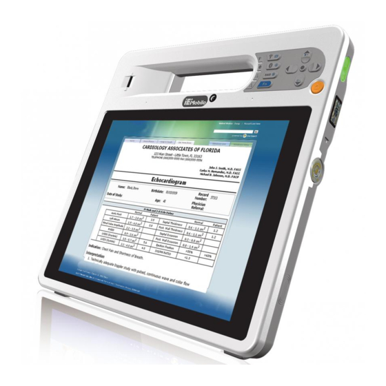
1.1 Overview Figure 1-1: ICEFIRE2-T10 The ICEFIRE2-T10 is a mobile clinic assistant with a 10.4 inch touch/digitizer screen and an IP 64 compliant front panel. The ICEFIRE2-T10 features a 1.86 GHz Intel® Atom™ N2800 with 4 GB 1333 MHz DDR3 SDRAM memory. -
Page 17: Features
RoHS compliant 1.3 Model Variations There are three models of the ICEFIRE2-T10 series. All of the models support wireless and Bluetooth connection and are equipped with the capacitive multi-touch screen and an 8 GB mSATA module. The model numbers and model variations are listed below. -
Page 18: Front Panel
ICEFIRE2-T10 Mobile Clinic Assistant 1.4 Front Panel The front panel of the ICEFIRE2-T10 has a 10.4” TFT XGA LCD that supports dual-mode input (digitizer and capacitive touch). The ICEFIRE2-T10 detects and switches the input mode automatically. The digitizer input mode is the priority if the two input modes are used at the same time. -
Page 19: Buttons And Indicators
ICEFIRE2-T10 Mobile Clinic Assistant 1.4.1 Buttons and Indicators Figure 1-3: Front Panel Buttons and Indicators There are several buttons and indicators on the front panel of the ICEFIRE2-T10 as show in the figure above. Following are descriptions of their functions: ... -
Page 20: Rear Panel
ICEFIRE2-T10 Mobile Clinic Assistant Navigation Keypad Up, Down Right, Left Center (select or enter) LED Indicators Wireless LED: Green light: 3.5G network is enabled Green light blinking: Wi-Fi is enabled Bluetooth LED: Blue light shows Bluetooth is enabled... -
Page 21: Side Panels
ICEFIRE2-T10 Mobile Clinic Assistant 1.6 Side Panels The side panels have connectors, button and readers as shown in F igure 1-5. 4 7 6 Figure 1-5: Side Panels CAUTION: DO NOT shine the light from the LED torch and the barcode scanner in eyes. -
Page 22: Bottom Panel
The bottom panel has a docking connector to connect with the optional docking station. Figure 1-7: Bottom Panel 1.9 Technical Specifications The technical specifications for the ICEFIRE2-T10 systems are listed in the table below. System ICEFIRE2-T10 1.86 GHz Intel® Atom™ N2800 Chipset Intel®... - Page 23 ICEFIRE2-T10 Mobile Clinic Assistant LED Torch 1 x LED torch (HU & TR models only) Barcode Scanner 1D laser/2D imager barcode scanner (HU & TR models only) Digitizer 2048 levels @ full scale pressure resolution (HU model only) Fingerprint Reader Yes (HU &...
-
Page 24: Table 1-2: Technical Specifications
ICEFIRE2-T10 Mobile Clinic Assistant Humidity 5% ~ 95% non-condensing Net weight 1.7 kg with Battery pack (150 g) IP level (front panel) IP 64 Safety CE, FCC, Medical-grade Class B (HU & TR models only) Connectors and Buttons I/O Ports and Switches 1 x 12 V DC input connector 1 x USB 3.0... -
Page 25: Dimensions
ICEFIRE2-T10 Mobile Clinic Assistant 1.10 Dimensions Figure 1-8: Dimensions (units in mm) Page 11... -
Page 26: Unpacking
ICEFIRE2-T10 Mobile Clinic Assistant Chapter Unpacking Page 12... -
Page 27: Unpack The Icefire2-T10
Check all the required parts are included Step 2: Install and charge the battery packs Step 3: Connect peripheral devices to the side panels of the ICEFIRE2-T10 Step 4: Connect the power cableS t e p 0 : Step 5: 2.1 Unpack the ICEFIRE2-T10... -
Page 28: Packing List
Lift the ICEFIRE2-T10 out of the boxes. Step 5: Remove the peripheral parts box from the main box. Step 6: S t e p 0 : 2.2 Packing List The ICEFIRE2-T10 is shipped with the following components: Quantity Item Image ICEFIRE2-T10 mobile clinic assistant Power cable... -
Page 29: Table 2-1: Packing List
ICEFIRE2-T10 Mobile Clinic Assistant Quantity Item Image Battery pack (P/N: 31603-000016-RS) (HU and TR models only) Battery pack-B (P/N: 31603-000020-RS) (ET model only) Utility CD (P/N: 7B000-000552-RS) One Key Recovery CD (P/N: IEI-7B000-000478-RS) Table 2-1: Packing List These optional items are also available. -
Page 30: Table 2-2: Optional Items
ICEFIRE2-T10 Mobile Clinic Assistant Item Image Smart card reader (P/N: ICEFIRE-T10A-SCR01-R10) Carrying bag (P/N: 7Z000-ICEFIRET10APOUCH-RS) Table 2-2: Optional Items Page 16... -
Page 31: Hardware Installation
ICEFIRE2-T10 Mobile Clinic Assistant Chapter Hardware Installation Page 17... -
Page 32: Battery Installation
ICEFIRE2-T10 Mobile Clinic Assistant 3.1 Battery Installation This section covers the installation of the battery pack. Make sure the battery latches are released. If not, unlock them by sliding latches Step 1: to the top. Figure 3-1: Release Battery Latches... -
Page 33: Figure 3-2: Battery Installation
ICEFIRE2-T10 Mobile Clinic Assistant Figure 3-2: Battery Installation Lock the battery by sliding the battery latches down to the battery. Step 3: Figure 3-3: Lock the Battery To view the battery capacity, push the battery capacity button on the battery. -
Page 34: Charge The Battery
The two batteries are hot swappable which means the user can replace the battery with a fully charged battery without turning off the system. 3.1.1 Charge the Battery The battery packs can be charged through the ICEFIRE2-T10 or the optional docking station. 3.1.1.1 Through the ICEFIRE2-T10 To charge the battery packs through the ICEFIRE2-T10, follow the steps below. -
Page 35: Through Optional Docking Station
ICEFIRE2-T10 Mobile Clinic Assistant The system starts to charge the battery packs. The battery capacity can be Step 4: checked via the capacity indicators on the battery ( F igure 3-4) or via the 4 7 6 Windows 7 power management screen ( F igure 3-5). -
Page 36: Sim Card Installation (Optional)
Step 3: 3.2 SIM Card Installation (Optional) The ICEFIRE2-T10-HU model is preinstalled a HSUPA module. To be able to use the 3G network connection, a SIM card must be installed in the ICEFIRE2-T10. Follow the steps below to install a SIM card. -
Page 37: Supported Frequency Range
ICEFIRE2-T10 Mobile Clinic Assistant Figure 3-7: SIM Card Slot Location Insert the SIM card into the slot. Step 3: Figure 3-8: SIM Card Installation 3.2.1 Supported Frequency Range T able 3-1 lists the frequency range supported by the optional Gobi3000™ WWLAN datacard. -
Page 38: Mounting The System (Optional)
Wall mounting with optional Docking Station The installation instructions are described in sections below. 3.3.1 Docking Station To place the ICEFIRE2-T10 on the optional docking station, follow the steps below. Release the docking station stand on the rear panel by unlocking the two Step 1: latches. -
Page 39: Figure 3-9: Release The Stand
ICEFIRE2-T10 Mobile Clinic Assistant Figure 3-9: Release the Stand Move the stand downward. Slide the two latches again to lock the stand into Step 2: place. Figure 3-10: Lock the Stand Secure the holder onto the top of the docking station by inserting four retention Step 3: screws (Figure 3-11). -
Page 40: Figure 3-11: Secure The Holder
ICEFIRE2-T10 Mobile Clinic Assistant Figure 3-11: Secure the Holder Insert the ICEFIRE2-T10 into the docking station. Snap the holder into place to Step 4: secure the ICEFIRE2-T10 from being damaged (Figure 3-12). Figure 3-12: Place the ICEFIRE2-T10 to the Docking Station... -
Page 41: Mounting With Docking Station
ICEFIRE2-T10 Mobile Clinic Assistant 3.3.2 Mounting with Docking Station The optional docking station of the ICEFIRE2-T10 can be installed on any VESA compliant mounting device. The VESA mount retention screw holes of the docking station are shown in F igure 3-13. Follow the instructions in the user manual of the mounting device to mount the docking station securely. -
Page 42: Usb Device Connection
Step 0: 3.4.2 USB Device Connection There is one USB 3.0 connector located on the right side of the ICEFIRE2-T10. To connect a USB device, please follow the instructions below. Located the USB connector. The location of the USB connector is shown in Step 1: F igure 1-5. -
Page 43: Smart Card Reader Installation (Optional)
ICEFIRE2-T10 Mobile Clinic Assistant Figure 3-15: USB Device Connection Insert the device connector. Once aligned, gently insert the USB device Step 4: connector into the on-board connector. Step 0: 3.4.2.1 Smart Card Reader Installation (Optional) To install the optional smart card reader, please follow the steps below. -
Page 44: Figure 3-17: Smart Card Reader Setting 1
ICEFIRE2-T10 Mobile Clinic Assistant Turn on the ICEFIRE2-T10 (refer to Section Step 3: 3 .6). Right click “Computer” from the start menu and select “Manage”. Step 4: Figure 3-17: Smart Card Reader Setting 1 The Computer Management window appears. Select “Service” from the left Step 5: panel. -
Page 45: Figure 3-18: Smart Card Reader Setting 2
ICEFIRE2-T10 Mobile Clinic Assistant Figure 3-18: Smart Card Reader Setting 2 Right click “Smart Card” and select “Properties”. Step 6: Figure 3-19: Smart Card Reader Setting 3 The Smart Card Properties window appears. Change the Startup type to Step 7: “Automatic”. -
Page 46: Figure 3-20: Smart Card Reader Setting 4
ICEFIRE2-T10 Mobile Clinic Assistant Figure 3-20: Smart Card Reader Setting 4 Page 32... -
Page 47: Docking Station I/O Connectors (Optional)
ICEFIRE2-T10 Mobile Clinic Assistant 3.5 Docking Station I/O Connectors (Optional) The I/O connectors on the rear panel of the ICEFIRE2-T10 Docking Station extend the capabilities of the ICEFIRE2-T10 but are not essential for operation (except power). Figure 3-21: Docking Station I/O Connectors 3.5.1 Serial Device Connection... -
Page 48: Serial Port Pinouts
ICEFIRE2-T10 Mobile Clinic Assistant Figure 3-22: Serial Device Connector Secure the connector. Secure the serial device connector to the external Step 3: interface by tightening the two retention screws on either side of the connector. Step 0: 3.5.1.1 RS-232 Serial Port Pinouts Following are the RS-232 serial port pinouts. -
Page 49: Vga Monitor Connection
ICEFIRE2-T10 Mobile Clinic Assistant 3.5.2 VGA Monitor Connection The ICEFIRE2-T10 Docking Station has a single female DB-15 connector on the bottom peripheral interface panel. The DB-15 connector is connected to a CRT or VGA monitor. To connect a second monitor to the ICEFIRE2-T10, please follow the instructions below. -
Page 50: Power-Up The System
ICEFIRE2-T10 Mobile Clinic Assistant 3.6 Power-up the System The power cable connects the power adapter to the power outlet. The power adapter and power cable are required for operation of the ICEFIRE2-T10. Connect the power adapter to the ICEFIRE2-T10. Step 1: Connect the power cable to the included power adapter. -
Page 51: Using Rfid Reader
ICEFIRE2-T10 Mobile Clinic Assistant NOTE: Push the power button again to suspend the system or to resume from the suspend mode. The solid green LED lights up when the system is in suspend mode. Push the power button for 3-4 seconds to shut down the system. The green LED turns off. -
Page 52: Figure 3-27: Irfr-100 Icon
ICEFIRE2-T10 Mobile Clinic Assistant Figure 3-27: IRFR-100 Icon The IRFR-100 window appears ( Step 3: F igure 3-28). Figure 3-28: IRFR Screen Page 38... -
Page 53: Figure 3-29: Irfr - Find Tags
ICEFIRE2-T10 Mobile Clinic Assistant Select the Find tags tab and click the Run button to enable the RFID reader Step 4: F igure 3-29). Figure 3-29: IRFR – Find Tags Use the RFID reader to read a RFID card, then the card number will be shown in... -
Page 54: Using Barcode Scanner
ICEFIRE2-T10 Mobile Clinic Assistant 3.8 Using Barcode Scanner There is a barcode scanner on the side panel ( F igure 1-5). To use the barcode scanner, follow the steps below. Push the barcode scanner button on the top panel to turn on the barcode Step 1: scanner. -
Page 55: Figure 3-33: Easyset - Communication
ICEFIRE2-T10 Mobile Clinic Assistant Click Communication on the tool bar and click Select communication Step 3: interface from the drop-down menu ( F igure 3-33). Figure 3-33: EasySet – Communication The Communication Interface window appears ( F igure 3-34). Select RS serial Step 4: or USB Virtual Com interface and click OK. -
Page 56: Figure 3-35: Connection Parameters Window
ICEFIRE2-T10 Mobile Clinic Assistant Figure 3-35: Connection Parameters Window To check if the barcode scanner is connected to the EasySet, click Step 6: Communication again and see if the original option (Connect) has been changed to Disconnect. Figure 3-36: Communication – Disconnect... -
Page 57: Barcode Setting
ICEFIRE2-T10 Mobile Clinic Assistant Figure 3-37: Barcode Information Display Area 3.8.1 Barcode Setting All of the barcode parameters can be modified through EasySet. To be able to modify the parameters, please make sure to connect the EasySet with the barcode scanner (refer to 3 .8). -
Page 58: Figure 3-38: Barcode Parameters
ICEFIRE2-T10 Mobile Clinic Assistant Figure 3-38: Barcode Parameters Use the Symbologies section to setup the format that can be read by the Step 2: barcode scanner (EA15). In the default setting, only the PDF417 format of 2-D barcodes is enabled. If other formats are needed, the user must enable them here. -
Page 59: Figure 3-39: Symbologies
ICEFIRE2-T10 Mobile Clinic Assistant Figure 3-39: Symbologies Use the Operating settings section to configure barcode triggering modes, Step 3: decoding security and beeps, etc. Figure 3-40: Operating Settings In the Scanning/Triggering section of operating settings, the user can set the Step 4: triggering mode, continuous, level, etc. -
Page 60: Figure 3-41: Scanning/Triggering
ICEFIRE2-T10 Mobile Clinic Assistant Figure 3-41: Scanning/Triggering In the Beeps/green indicator LED section of operating settings, the user can Step 5: configure the beep sound of the barcode scanner. Step 0: Figure 3-42: Beeps/Green Indicator LED Page 46... - Page 61 ICEFIRE2-T10 Mobile Clinic Assistant NOTE: If no beep sound, please check if the “rtkhdaud.dat” file is in C:\windows\system32\drivers Page 47...
-
Page 62: Driver Installation
ICEFIRE2-T10 Mobile Clinic Assistant Chapter Driver Installation Page 48... -
Page 63: Available Software Drivers
RFID driver ICEFIRE Control Center All drivers are located in “ICEFIRE2-T10 Driver” folder of the system. Installation instructions are given below. 4.2 Intel® Chipset Driver To install the chipset driver, please follow the steps below. Select 1.CHIPSET from the list in Step 1: F igure 4-1. -
Page 64: Figure 4-1: Chipset Driver Location
ICEFIRE2-T10 Mobile Clinic Assistant Figure 4-1: Chipset Driver Location Double click the setup file in the folder. The Intel® Chipset Device Software Step 2: welcome screen appears ( F igure 4-2). Figure 4-2: Intel® Chipset Device Software Follow the step-by-step instruction of the installation wizard to install the Step 3: graphics driver. -
Page 65: Intel® Graphics Driver
ICEFIRE2-T10 Mobile Clinic Assistant 4.3 Intel® Graphics Driver To install the graphics driver, please follow the steps below. Select 2.Graphics from the list in F igure 4-3. Step 1: 4 7 6 Figure 4-3: Graphics Driver Location Double click the setup file in the folder. The Graphics Media Accelerator... -
Page 66: Realtek Lan Driver
ICEFIRE2-T10 Mobile Clinic Assistant Figure 4-4: Graphics Media Accelerator Driver Follow the step-by-step instruction of the installation wizard to install the Step 3: graphics driver. 4.4 Realtek LAN Driver To install the Realtek LAN driver, please follow the steps below. -
Page 67: Figure 4-5: Realtek Lan Driver Location
ICEFIRE2-T10 Mobile Clinic Assistant Figure 4-5: Realtek LAN Driver Location Double click the setup file in the folder. The InstallShield Wizard screen appears Step 2: F igure 4-6). 4 7 6 Figure 4-6: Realtek LAN InstallShield Wizard Page 53... -
Page 68: Audio Driver
ICEFIRE2-T10 Mobile Clinic Assistant Follow the step-by-step instruction of the installation wizard to install the LAN Step 3: driver. 4.5 Audio Driver To install the driver for the speaker and the microphone, please follow the steps below. Select 4.Audio from the list in Step 1: F igure 4-7. -
Page 69: Barcode Scanner Driver
ICEFIRE2-T10 Mobile Clinic Assistant Figure 4-8: Realtek HD Audio Driver InstallShield Wizard Follow the step-by-step instruction of the installation wizard to install the HD Step 3: Audio driver. 4.6 Barcode Scanner Driver To install the barcode scanner driver, please follow the steps below. -
Page 70: Figure 4-9: Barcode Scanner Driver Location
ICEFIRE2-T10 Mobile Clinic Assistant Figure 4-9: Barcode Scanner Driver Location Double click the setup file in the folder. The InstallShield Wizard screen appears. Step 2: Figure 4-10: Barcode Driver InstallShield Wizard Follow the step-by-step instruction of the installation wizard to install the barcode Step 3: scanner driver. -
Page 71: Fingerprint Reader Driver
ICEFIRE2-T10 Mobile Clinic Assistant 4.7 Fingerprint Reader Driver To install the fingerprint reader driver, please follow the steps below. Select 6.FINGER PRINT from the list in Step 1: F igure 4-11. 5 7 6 Figure 4-11: Fingerprint Reader Driver Location Double click the setup file in the folder. -
Page 72: Bluetooth Driver
ICEFIRE2-T10 Mobile Clinic Assistant Follow the step-by-step instruction of the installation wizard to install the Step 3: fingerprint reader driver. 4.8 Bluetooth Driver To install the Bluetooth driver, please follow the steps below. Turn on the Bluetooth by pushing the Bluetooth on/off button on the front Step 1: panel. -
Page 73: Wireless Lan Driver
ICEFIRE2-T10 Mobile Clinic Assistant Figure 4-14: Bluetooth Driver InstallShield Wizard Follow the step-by-step instruction of the installation wizard to install the Step 4: Bluetooth driver. 4.9 Wireless LAN Driver To install the wireless LAN driver, please follow the steps below. -
Page 74: Figure 4-15: Wireless Lan Driver Location
ICEFIRE2-T10 Mobile Clinic Assistant Figure 4-15: Wireless LAN Driver Location Double click the setup file in the folder. The InstallShield Wizard screen appears. Step 2: Page 60... -
Page 75: Module Driver
ICEFIRE2-T10 Mobile Clinic Assistant Figure 4-16: Bluetooth Driver InstallShield Wizard Follow the step-by-step instruction of the installation wizard to install the Step 3: Wireless LAN driver. 4.10 3G Module Driver There one driver and watcher program need to be installed for the 3G module. To install the 3G driver and program, please follow the steps below. -
Page 76: Figure 4-17: 3G Module Driver Location
ICEFIRE2-T10 Mobile Clinic Assistant Figure 4-17: 3G Module Driver Location Double click the setup file in the folder. Follow the step-by-step instruction of the Step 2: installation wizard to install the module driver ( F igure 4-18). Page 62... -
Page 77: Figure 4-18: 3G Module Driver Installshield Wizard
ICEFIRE2-T10 Mobile Clinic Assistant Figure 4-18: 3G Module Driver InstallShield Wizard Select Watcher_GobiAnywhere_B2964 folder from the 8.3G Module folder as Step 3: shown in F igure 4-19. 4 7 6 Figure 4-19: 3G Module Watcher Location Double click the setup file in the folder. Follow the step-by-step instruction of the... -
Page 78: Usb 3.0 Driver
ICEFIRE2-T10 Mobile Clinic Assistant Figure 4-20: 3G Module Program InstallShield Wizard 4.11 USB 3.0 Driver To install the USB 3.0 driver, please follow the steps below. Select 9.USB 3.0 from the list in F igure 4-21. Step 1: Page 64... -
Page 79: Figure 4-21: Usb 3.0 Driver Location
ICEFIRE2-T10 Mobile Clinic Assistant Figure 4-21: USB 3.0 Driver Location Right click the setup file in the folder and select Run as administrator. Step 2: Figure 4-22: Barcode Driver InstallShield Wizard The InstallShield Wizard screen appears. Follow the step-by-step instruction of Step 3: the installation wizard to install the barcode scanner driver. -
Page 80: Rfid Driver
ICEFIRE2-T10 Mobile Clinic Assistant 4.12 RFID Driver To install the RFID driver, please follow the steps below. Select 10.RFID from the list in Step 1: F igure 4-23. 4 7 6 Figure 4-23: RFID Driver Location Double click the RFID Driver setup file in the folder to install the RFID driver Step 2: F igure 4-24). -
Page 81: Icefire Control Center
ICEFIRE2-T10 Mobile Clinic Assistant Figure 4-24: RFID Driver Installation Copy the IRFR-100-BEEP program to the desktop. Use the IRFR-100 to Step 3: configure and read RFID. Refer to Section 3 .7 for detailed instruction. Figure 4-25: RFID Program Location 4.13 ICEFIRE Control Center To install the ICEFIRE Control Center, please follow the steps below. -
Page 82: Figure 4-26: Icefire Control Center Driver Location
ICEFIRE2-T10 Mobile Clinic Assistant Figure 4-26: ICEFIRE Control Center Driver Location The ICEFIRE Controlcenter folder contains tthree drivers shown in Step 2: F igure 4-27. Follow the step-by-step instruction of the installation wizard to install these driver/programs by order listed below: .NET Framework 4.0... -
Page 83: Icefire Control Center
ICEFIRE2-T10 Mobile Clinic Assistant Chapter ICEFIRE Control Center Page 69... -
Page 84: Getting Started
ICEFIRE2-T10 Mobile Clinic Assistant 5.1 Getting Started The ICEFIRE control center puts many tasks and common settings in a single window. To launch Control Center, click the icon on the desktop. The Control Center interface is shown below. Figure 5-1: Control Center 5.2 Features... -
Page 85: Module Status
The indicator in F igure 5-3 shows Bluetooth module is on. The Bluetooth-enabled device can be used with the ICEFIRE2-T10. Figure 5-3: Function Indicator - On Repeat the same steps to turn on or turn off other modules listed in F igure 5-4. -
Page 86: Camera Settings
ICEFIRE2-T10 Mobile Clinic Assistant Figure 5-4: Module Status 5.4 Camera Settings The ICEFIRE Control Center allows users to set the resolutions of the webcams on the front panel and the rear panel. The file path to save the pictures taken by the webcams can also be configured through the Control Center. -
Page 87: Calibration
Figure 5-6: Camera Settings 5.5 Calibration Using a digitizer or touch to interact with the ICEFIRE2-T10 is more frequent than using a mouse and keyboard. The user should calibrate the digitizer and touch for the first time using the system and whenever the touch point does not align properly. -
Page 88: Figure 5-8: Tablet Pc Settings
ICEFIRE2-T10 Mobile Clinic Assistant Figure 5-8: Tablet PC Settings Select an input type to calibrate. Step 3: Figure 5-9: Calibrate Pen or Touch Input Screens Follow the instructions in the calibration program to calibrate. Step 4: Page 74... -
Page 89: Programmable Buttons
ICEFIRE2-T10 Mobile Clinic Assistant 5.6 Programmable Buttons As become more familiar with the ICEFIRE2-T10, the user may want to customize the keys on the front panel. The user can configure the keys to launch the favorite program, run a command or enter a key combination. -
Page 90: Figure 5-11: Button Actions - Wifi
ICEFIRE2-T10 Mobile Clinic Assistant Figure 5-11: Button Actions - Wifi Both sections have a list of action to be performed. Select one action from the Step 3: list. Once settings are completed click the “Done” button to save the settings. -
Page 91: Action: Open Process
ICEFIRE2-T10 Mobile Clinic Assistant Enable Camera Open camera application Enable/Disable Barcode Execute barcode reading Enable/Disable RFID Execute RFID reading Enable Flashlight Execute flashlight (LED torch) Windows Key Action Execute windows key actions (see Section 5 .6.2) Table 5-1: Action Description 5.6.1 Action: Open Process... -
Page 92: Action: Windows Key Action
ICEFIRE2-T10 Mobile Clinic Assistant 5.6.2 Action: Windows Key Action If Windows Key Action is selected, the user has to select any one of windows key from “Key Selection” list ( F igure 5-13). Figure 5-13: Action - Windows Key Action... -
Page 93: Bios Setup
ICEFIRE2-T10 Mobile Clinic Assistant Chapter BIOS Setup Page 79... -
Page 94: Introduction
ICEFIRE2-T10 Mobile Clinic Assistant 6.1 Introduction The BIOS is programmed onto the BIOS chip. The BIOS setup program allows changes to certain system settings. This chapter outlines the options that can be changed. NOTE: Some of the BIOS options may vary throughout the life cycle of the product and are subject to change without prior notice. -
Page 95: Getting Help
ICEFIRE2-T10 Mobile Clinic Assistant Function Increase the numeric value or make changes Decrease the numeric value or make changes Page up Move to the next page Page down Move to the previous page Main Menu – Quit and do not save changes into CMOS... -
Page 96: Main
ICEFIRE2-T10 Mobile Clinic Assistant The following sections completely describe the configuration options found in the menu items at the top of the BIOS screen and listed above. 6.2 Main The Main BIOS menu ( B IOS Menu 1) appears when the BIOS Setup program is entered. -
Page 97: Advanced
ICEFIRE2-T10 Mobile Clinic Assistant System Date [xx/xx/xx] Use the System Date option to set the system date. Manually enter the day, month and year. System Time [xx:xx:xx] Use the System Time option to set the system time. Manually enter the hours, minutes and seconds. -
Page 98: Acpi Settings
ICEFIRE2-T10 Mobile Clinic Assistant 6.3.1 ACPI Settings The ACPI Settings menu ( B IOS Menu 3) configures the Advanced Configuration and Power Interface (ACPI) options. Aptio Setup Utility – Copyright (C) 2011 American Megatrends, Inc. Advanced ACPI Settings Select the highest ACPI... -
Page 99: Rtc Wake Settings
ICEFIRE2-T10 Mobile Clinic Assistant 6.3.2 RTC Wake Settings The RTC Wake Settings menu ( B IOS Menu 4) configures RTC wake event. Aptio Setup Utility – Copyright (C) 2011 American Megatrends, Inc. Advanced Wake system with Fixed Time [Disabled] Enable or disable System wake on alarm event. -
Page 100: Cpu Configuration
ICEFIRE2-T10 Mobile Clinic Assistant If selected, the following appears with values that Enabled can be selected: *Wake up every day *Wake up date *Wake up hour *Wake up minute *Wake up second After setting the alarm, the computer turns itself on from a suspend state when the alarm goes off. -
Page 101: Hyper Threading [Enabled]
ICEFIRE2-T10 Mobile Clinic Assistant Aptio Setup Utility – Copyright (C) 2011 American Megatrends, Inc. Advanced CPU Configuration Processor Type Intel(R) Atom(TM) CPU N2800 @ 1.86GHz ---------------------- EMT64 Supported : Select Screen Processor Speed 1865 MHz : Select Item System But Speed... -
Page 102: Ide Configuration
ICEFIRE2-T10 Mobile Clinic Assistant Enables the use of hyper threading technology Enabled EFAULT 6.3.4 IDE Configuration Use the IDE Configuration menu ( B IOS Menu 6) to change and/or set the configuration 5 8 6 of the SATA devices installed in the system. -
Page 103: Usb Configuration
ICEFIRE2-T10 Mobile Clinic Assistant 6.3.5 USB Configuration Use the USB Configuration menu ( B IOS Menu 7) to read USB configuration information 5 8 6 and configure the USB settings. Aptio Setup Utility – Copyright (C) 2011 American Megatrends, Inc. -
Page 104: It8519 Serial Ports Configuration
ICEFIRE2-T10 Mobile Clinic Assistant Legacy USB support disabled Disabled Legacy USB support disabled if no USB devices are Auto connected 6.3.6 IT8519 Serial Ports Configuration Use the IT8519 Serial Ports Configuration menu ( B IOS Menu 8) to set or change the configurations for the serial ports. -
Page 105: Serial Port 1 Configuration
ICEFIRE2-T10 Mobile Clinic Assistant 6.3.6.1 Serial Port 1 Configuration Use the Serial Port n Configuration menu ( B IOS Menu 9) to configure the serial port 1 on the docking station. Aptio Setup Utility – Copyright (C) 2011 American Megatrends, Inc. -
Page 106: H/W Monitor
ICEFIRE2-T10 Mobile Clinic Assistant Serial Port I/O port address is 3E8h and the interrupt IO=3E8h; address is IRQ3, 4 IRQ=3, 4 Serial Port I/O port address is 2F8h and the interrupt IO=2F8h; address is IRQ3, 4 IRQ=3, 4 ... -
Page 107: Serial Port Console Redirection
ICEFIRE2-T10 Mobile Clinic Assistant System Temperature CPU Temperature 6.3.8 Serial Port Console Redirection The Serial Port Console Redirection menu ( B IOS Menu 11) allows the console redirection options to be configured. Console redirection allows users to maintain a system remotely by re-directing keyboard input and text output through the serial port. -
Page 108: Chipset
ICEFIRE2-T10 Mobile Clinic Assistant Aptio Setup Utility – Copyright (C) 2011 American Megatrends, Inc. Advanced iEi Feature Auto Recovery Function Reboot and recover Auto Recovery Function [Disabled] system automatically within 10 min, when OS crashes. Please install Auto Recovery API... -
Page 109: Host Bridge Configuration
ICEFIRE2-T10 Mobile Clinic Assistant Aptio Setup Utility – Copyright (C) 2011 American Megatrends, Inc. Main Advanced Chipset Boot Security Save & Exit > Host Bridge North Bridge Parameters > South Bridge --------------------- : Select Screen : Select Item Enter Select... -
Page 110: Intel Igd Configuration
ICEFIRE2-T10 Mobile Clinic Assistant 6.4.1.1 Intel IGD Configuration Use the Intel IGD Configuration menu to configure the video device connected to the system. Aptio Setup Utility – Copyright (C) 2011 American Megatrends, Inc. Advanced Intel IGD Configuration Select the Video Device... -
Page 111: Active Lfp [Int-Lvds]
ICEFIRE2-T10 Mobile Clinic Assistant 800x480-18BIT 1280x1024-18BIT 800x600-24BIT 1400x1050-48BIT 1024x600-18BIT 1440x900-18BIT 1024x768-18BIT EFAULT Active LFP [Int-LVDS] Use the Active LFP option to select the Active LFP configuration. BIOS does not enable LVDS. -
Page 112: South Bridge Configuration
ICEFIRE2-T10 Mobile Clinic Assistant 6.4.2 South Bridge Configuration Use the South Bridge Configuration menu ( B IOS Menu 16) to configure the 5 8 6 Southbridge chipset. Aptio Setup Utility – Copyright (C) 2011 American Megatrends, Inc. Chipset 3G Function... -
Page 113: Boot
ICEFIRE2-T10 Mobile Clinic Assistant The system remains turned off Power Off EFAULT The system turns on Power On The system returns to its previous state. If it was on, it Last State turns itself on. If it was off, it remains off. -
Page 114: Quiet Boot [Enabled]
ICEFIRE2-T10 Mobile Clinic Assistant Does not enable the keyboard Number Lock automatically. To use the 10-keys on the keyboard, press the Number Lock key located on the upper left-hand corner of the 10-key pad. The Number Lock LED on the keyboard lights up when the Number Lock is engaged. -
Page 115: Security
ICEFIRE2-T10 Mobile Clinic Assistant Hard Drive BBS Priorities Use the Hard Drive BBS Priorities option to set the order of the legacy devices in this group. 6.6 Security Use the Security menu ( B IOS Menu 18) to set system and user passwords. -
Page 116: Save Changes And Reset
ICEFIRE2-T10 Mobile Clinic Assistant Aptio Setup Utility – Copyright (C) 2011 American Megatrends, Inc. Main Advanced Chipset Boot Security Save & Exit Save Changes and Reset Exit system setup after Discard Changes and Reset saving the changes. Restore Defaults Save as User Defaults... -
Page 117: System Maintenance
ICEFIRE2-T10 Mobile Clinic Assistant Chapter System Maintenance Page 103... -
Page 118: System Maintenance Introduction
ICEFIRE2-T10 Mobile Clinic Assistant 7.1 System Maintenance Introduction If the components of the ICEFIRE2-T10 fail they must be replaced, such as the wireless LAN module or the motherboard. Please contact the system reseller or vendor to purchase the replacement parts. -
Page 119: Turn Off The Power
The motherboard is accessible after opening the rear cover. 7.5 mSATA Module Replacement The ICEFIRE2-T10 is preinstalled with an mSATA module. If the mSATA module is fail, follow the instructions below to replace the mSATA module. Follow all anti-static procedures. See Section 7 .2. -
Page 120: Figure 7-1: Msata Access Panel Retention Screws
ICEFIRE2-T10 Mobile Clinic Assistant Figure 7-1: mSATA Access Panel Retention Screws Locate the mSATA module. Remove the two retention screws to release the Step 4: mSATA module. Figure 7-2: mSATA Module Retention Screws Removal Page 106... -
Page 121: Figure 7-3: Msata Module Removal
ICEFIRE2-T10 Mobile Clinic Assistant Grasp the mSATA module by the edges and carefully pull it out of the socket. Step 5: Figure 7-3: mSATA Module Removal Install a new mSATA module by inserting the card into the slot at an angle. -
Page 122: Interface Connectors
ICEFIRE2-T10 Mobile Clinic Assistant Chapter Interface Connectors Page 108... -
Page 123: Peripheral Interface Connectors
ICEFIRE2-T10 Mobile Clinic Assistant 8.1 Peripheral Interface Connectors The ICEFIRE2-T10 series’ motherboard comes with a number of peripheral interface connectors and configuration jumpers. The connector locations are shown in Figure 8-1 and Figure 8-2. The Pin 1 locations of the on-board connectors are also indicated in the diagrams below. -
Page 124: Internal Peripheral Connectors
Internal peripheral connectors are found on the motherboard and are only accessible when the motherboard is outside of the chassis. The table below shows a list of the peripheral interface connectors on the ICEFIRE2-T10 motherboard. Pinouts of these connectors can be found in the following sections. -
Page 125: Table 8-1: Peripheral Interface Connectors
ICEFIRE2-T10 Mobile Clinic Assistant Connector Type Label Digitizer sensor connector 12-pin wafer Docking connector 30-pin FPC Ethernet connector RJ-45 LAN1 External battery connectors 5-pin connector CON1, CON2 Fan connector (1) 3-pin wafer FAN1 Fan connector (2) 4-pin wafer FAN2 Fingerprint reader connector... -
Page 126: Barcode Connector (Barcode1)
ICEFIRE2-T10 Mobile Clinic Assistant 8.2.1 Barcode Connector (BARCODE1) PIN NO. DESCRIPTION PIN NO. DESCRIPTION VCC3 TXD2 BAR_TRI# BAREN# RXD2 CTS#2 Pull high to 3.3V RTS#2 BAR_BUZ DETECT0 Table 8-2: Barcode Connector (BARCODE1) Pinouts 8.2.2 Battery Connector (BAT1) PIN NO. DESCRIPTION... -
Page 127: Button Connector (Btn1)
ICEFIRE2-T10 Mobile Clinic Assistant 8.2.4 Button Connector (BTN1) PIN NO. DESCRIPTION BAR_BTN# RFID_BTN# RFID_LED LIGHT_BTN#_EC KSO15 Table 8-5: Button Connector (BTN1) Pinouts 8.2.5 Rear Camera Connector (CAMARE1) PIN NO. DESCRIPTION CAMERA_TRI# USB_PP4 USB_PN4 VCC3 Table 8-6: Rear Camera Connector (CAMARE1) Pinouts 8.2.6 Front Camera Connector (CAMARA2) -
Page 128: Camera Shutter Connector (Camsw1)
ICEFIRE2-T10 Mobile Clinic Assistant 8.2.7 Camera Shutter Connector (CAMSW1) PIN NO. DESCRIPTION CAMERA_SW# CAMERA_TRI# Table 8-8: Camera Shutter Connector (CAMSW1) Pinouts 8.2.8 Debug Connector (DBG_PORT1) PIN NO. DESCRIPTION PIN NO. DESCRIPTION LAD2 LPC_CLK33M LAD3 BUF_PLTRST# LFRAME LAD0 VCC3 LAD1 Table 8-9: Debug Connector (DBG_PORT1) Pinouts 8.2.9 Digitizer Sensor Connector (CN1) -
Page 129: Docking Connector (J4)
ICEFIRE2-T10 Mobile Clinic Assistant 8.2.10 Docking Connector (J4) PIN NO. DESCRIPTION PIN NO. DESCRIPTION DOCKEN# VIN_DOCK USB2-_GL850 NTX1 USB2+_GL850 NCTS1 NDTR1 USB3-_GL850_C NRI1 USB3+_GL850_C NDSR1 NRX1 5VDDCDA NDCD1 5VDDCLK NRTS1 VIN_DOCK BLUE VIN_DOCK GREEN VIN_DOCK VIN_DOCK Table 8-11: Docking Connector (J4) Pinouts 8.2.11 Fan Connector (FAN1) -
Page 130: Fan Connector (Fan2)
ICEFIRE2-T10 Mobile Clinic Assistant 8.2.12 Fan Connector (FAN2) PIN NO. DESCRIPTION FAN_TACH VCC5 FAN_PWM Table 8-13: Fan Connector (FAN2) Pinouts 8.2.13 Fingerprint Reader Connector (FINPRT1) PIN NO. DESCRIPTION VCC3 USB_PN2 USB_PP2 Table 8-14: Fingerprint Reader Connector (FINPRT1) Pinouts 8.2.14 GPS Connector (GPS1) PIN NO. -
Page 131: Keyboard Connector (Lpt_Db1)
ICEFIRE2-T10 Mobile Clinic Assistant 8.2.15 Keyboard Connector (LPT_DB1) PIN NO. DESCRIPTION PIN NO. DESCRIPTION KSI0 KSO9 KSO0 KSO10 KSO1 KSO12 KSO2 KSI1 KSO3 KSO11 KSO4 KSI2 KSO5 KSI3 KSO6 KSO7 KSO8 Table 8-16: Keyboard Connector (LPT_DB1) Pinouts 8.2.16 Keypad Connector (KEYPAD1) PIN NO. -
Page 132: Lvds Connector (Cn2)
ICEFIRE2-T10 Mobile Clinic Assistant 8.2.18 LVDS Connector (CN2) PIN NO. DESCRIPTION PIN NO. DESCRIPTION VCC_LCD VCC_LCD VCC_LCD VCC_LCD/2 LVDS_DN0 LVDS_DP0 LVDS_DN1 LVDS_DP1 LVDS_DN2 LVDS_DP2 LVDS_CLKN LVDS_CLKP EXTLD EXTLD EXTLD EXTLD LVDS_DN3 LVDS_DP3 PANEL_BKLTEN BRI_CTRL Table 8-19: LVDS Connector (CN2) Pinouts 8.2.19 Microphone Connector (AMIC1) -
Page 133: Power Input Connector (Pw1)
ICEFIRE2-T10 Mobile Clinic Assistant 8.2.20 Power Input Connector (PW1) PIN NO. DESCRIPTION EXT_VINC EXT_VINC Table 8-21: Power Input Connector (PW1) Pinouts 8.2.21 Power Button Connector (PWRBTN1) PIN NO. DESCRIPTION EC_PWRBTN# POWERLED VCC3DUAL Table 8-22: Power Button Connector (PWRBTN1) Pinouts 8.2.22 RFID Connector (RFID1) PIN NO. -
Page 134: Speaker Connector (Spk1)
ICEFIRE2-T10 Mobile Clinic Assistant 8.2.23 Speaker Connector (SPK1) PIN NO. DESCRIPTION Table 8-24: Speaker Connector (SPK1) Pinouts 8.2.24 SPI Flash Connector (SPI1) PIN NO. DESCRIPTION +V3.3_SPI FSCE#_R FMISO_R FSCK_R FMOSI_R Table 8-25: SPI Flash Connector (SPI1) Pinouts 8.2.25 SPI Flash Connector (SPI2) PIN NO. -
Page 135: Touch Panel Connector (Touch1)
ICEFIRE2-T10 Mobile Clinic Assistant 8.2.26 Touch Panel Connector (TOUCH1) PIN NO. DESCRIPTION PDCT_ECI USB_PP6 USB_PN6 TH_POWER Table 8-27: Touch Panel Connector (TOUCH1) Pinouts Page 121... -
Page 136: A Safety Precautions
ICEFIRE2-T10 Mobile Clinic Assistant Appendix Safety Precautions Page 122... -
Page 137: Safety Precautions
Do not apply voltage levels that exceed the specified voltage range. Doing so may cause fire and/or an electrical shock. Electric shocks can occur if the ICEFIRE2-T10 chassis is opened when the ICEFIRE2-T10 is running. Do not drop or insert any objects into the ventilation openings of the ICEFIRE2-T10. -
Page 138: Anti-Static Precautions
Electrostatic discharge (ESD) can cause serious damage to electronic components, including the ICEFIRE2-T10. Dry climates are especially susceptible to ESD. It is therefore critical that whenever the ICEFIRE2-T10 is opened and any of the electrical components are handled, the following anti-static precautions are strictly adhered to. -
Page 139: Product Disposal
Please follow the national guidelines for electrical and electronic product disposal. A.2 Maintenance and Cleaning Precautions When maintaining or cleaning the ICEFIRE2-T10, please follow the guidelines below. A.2.1 Maintenance and Cleaning Prior to cleaning any part or component of the ICEFIRE2-T10, please read the details below. Page 125... -
Page 140: Cleaning Tools
Some components in the ICEFIRE2-T10 may only be cleaned using a product specifically designed for the purpose. In such case, the product will be explicitly mentioned in the cleaning tips. Below is a list of items to use when cleaning the ICEFIRE2-T10. ... -
Page 141: Bbios Options
ICEFIRE2-T10 Mobile Clinic Assistant Appendix BIOS Options Page 127... - Page 142 ICEFIRE2-T10 Mobile Clinic Assistant Below is a list of BIOS configuration options in the BIOS chapter. BIOS Information .........................82 System Date [xx/xx/xx] ......................83 System Time [xx:xx:xx] .......................83 ACPI Sleep State [S1 (CPU Stop Clock)] ................84 ...
- Page 143 ICEFIRE2-T10 Mobile Clinic Assistant Save as User Defaults ...................... 102 Restore User Defaults ...................... 102 Page 129...
-
Page 144: C Terminology
ICEFIRE2-T10 Mobile Clinic Assistant Appendix Terminology Page 130... - Page 145 ICEFIRE2-T10 Mobile Clinic Assistant Audio Codec 97 (AC’97) refers to a codec standard developed by Intel® AC ’97 in 1997. Advanced Configuration and Power Interface (ACPI) is an OS-directed ACPI configuration, power management, and thermal management interface. Advanced Host Controller Interface (AHCI) is a SATA Host controller AHCI register-level interface.
- Page 146 ICEFIRE2-T10 Mobile Clinic Assistant Direct Memory Access (DMA) enables some peripheral devices to bypass the system processor and communicate directly with the system memory. Dual Inline Memory Modules are a type of RAM that offer a 64-bit data DIMM bus and have separate electrical contacts on each side of the module.
- Page 147 ICEFIRE2-T10 Mobile Clinic Assistant Liquid crystal display (LCD) is a flat, low-power display device that consists of two polarizing plates with a liquid crystal panel in between. Low-voltage differential signaling (LVDS) is a dual-wire, high-speed LVDS differential electrical signaling system commonly used to connect LCD displays to a computer.
-
Page 148: D Watchdog Timer
ICEFIRE2-T10 Mobile Clinic Assistant Appendix Watchdog Timer Page 134... - Page 149 ICEFIRE2-T10 Mobile Clinic Assistant NOTE: The following discussion applies to DOS environment. IEI support is contacted or the IEI website visited for specific drivers for more sophisticated operating systems, e.g., Windows and Linux. The Watchdog Timer is provided to ensure that standalone systems can always recover from catastrophic conditions that cause the CPU to crash.
-
Page 150: Example Program
ICEFIRE2-T10 Mobile Clinic Assistant NOTE: When exiting a program it is necessary to disable the Watchdog Timer, otherwise the system resets. Example program: ; INITIAL TIMER PERIOD COUNTER W_LOOP: AX, 6F02H ;setting the time-out value BL, 30 ;time-out value is 48 seconds ;... -
Page 151: E Hazardous Materials Disclosure
ICEFIRE2-T10 Mobile Clinic Assistant Appendix Hazardous Materials Disclosure Page 137... -
Page 152: Ipb Products Certified As Ercury
ICEFIRE2-T10 Mobile Clinic Assistant E.1 Hazardous Materials Disclosure Table for IPB Products Certified as RoHS Compliant Under 2002/95/EC Without Mercury The details provided in this appendix are to ensure that the product is compliant with the Peoples Republic of China (China) RoHS standards. The table below acknowledges the presences of small quantities of certain materials in the product, and is applicable to China RoHS only. - Page 153 ICEFIRE2-T10 Mobile Clinic Assistant Part Name Toxic or Hazardous Substances and Elements Lead Mercury Cadmium Hexavalent Polybrominated Polybrominated (Pb) (Hg) (Cd) Chromium Biphenyls Diphenyl Ethers (CR(VI)) (PBB) (PBDE) Housing Display Printed Circuit Board Metal Fasteners Cable Assembly Fan Assembly Power Supply...
- Page 154 ICEFIRE2-T10 Mobile Clinic Assistant 此附件旨在确保本产品符合中国 RoHS 标准。以下表格标示此产品中某有毒物质的含量符 合中国 RoHS 标准规定的限量要求。 本产品上会附有”环境友好使用期限”的标签,此期限是估算这些物质”不会有泄漏或突变”的 年限。本产品可能包含有较短的环境友好使用期限的可替换元件,像是电池或灯管,这些元 件将会单独标示出来。 部件名称 有毒有害物质或元素 铅 汞 镉 六价铬 多溴联苯 多溴二苯醚 (Pb) (Hg) (Cd) (CR(VI)) (PBB) (PBDE) 壳体 显示 印刷电路板 金属螺帽 电缆组装 风扇组装 电力供应组装 电池 O: 表示该有毒有害物质在该部件所有物质材料中的含量均在 SJ/T11363-2006 标准规定的限量要求以下。 X: 表示该有毒有害物质至少在该部件的某一均质材料中的含量超出 SJ/T11363-2006 标准规定的限量要求。...
Need help?
Do you have a question about the ICEFIRE2-T10 and is the answer not in the manual?
Questions and answers