Sign In
Upload
Manuals
Brands
IEI Technology Manuals
Touch Panel
ICEFIRE2-T10
User Manuals: IEI Technology ICEFIRE2-T10 Touch Panel
Manuals and User Guides for IEI Technology ICEFIRE2-T10 Touch Panel. We have
1
IEI Technology ICEFIRE2-T10 Touch Panel manual available for free PDF download: User Manual
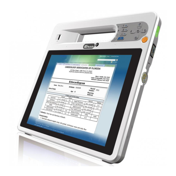
IEI Technology ICEFIRE2-T10 User Manual (154 pages)
10.4” Mobile Clinic Assistant
Brand:
IEI Technology
| Category:
Touch Panel
| Size: 7 MB
Table of Contents
Table of Contents
4
1 Introduction
15
Overview
16
Features
17
Model Variations
17
Table 1-1: Model Variations
17
Front Panel
18
Figure 1-2: Front Panel
18
Buttons and Indicators
19
Figure 1-3: Front Panel Buttons and Indicators
19
Rear Panel
20
Figure 1-4: Rear Panel
20
Side Panels
21
Top Panel
21
Figure 1-5: Side Panels
21
Bottom Panel
22
Technical Specifications
22
Figure 1-6: Top Panel
22
Figure 1-7: Bottom Panel
22
Table 1-2: Technical Specifications
24
Dimensions
25
Figure 1-8: Dimensions (Units in MM)
25
2 Unpacking
26
Unpack the Icefire2-T10
27
Packing List
28
Table 2-1: Packing List
29
Table 2-2: Optional Items
30
3 Hardware Installation
31
Battery Installation
32
Figure 3-1: Release Battery Latches
32
Figure 3-2: Battery Installation
33
Figure 3-3: Lock the Battery
33
Charge the Battery
34
Figure 3-4: Battery Capacity Indicators
34
Through the ICEFIRE2-T10
34
Figure 3-5: Windows 7 Power Management Screen
35
Through Optional Docking Station
35
SIM Card Installation (Optional)
36
Figure 3-6: Insert Batteries to Docking Station
36
Figure 3-7: SIM Card Slot Location
37
Figure 3-8: SIM Card Installation
37
SIM C ARD I NSTALLATION 3.2.1 Supported Frequency Range
37
Supported Frequency Range
37
Mounting the System (Optional)
38
Docking Station
38
Table 3-1: Supported Frequency Range
38
Figure 3-10: Lock the Stand
39
Figure 3-9: Release the Stand
39
Figure 3-11: Secure the Holder
40
Figure 3-12: Place the ICEFIRE2-T10 to the Docking Station
40
Mounting with Docking Station
41
I/O Connectors
41
Figure 3-13: VESA Mounting Retention Screw Holes (Docking Station)
41
LAN Connection
41
Figure 3-14: LAN Connection
42
USB Device Connection
42
Figure 3-15: USB Device Connection
43
Figure 3-16: Smart Card Reader Installation
43
Smart Card Reader Installation (Optional)
43
Figure 3-17: Smart Card Reader Setting 1
44
Figure 3-18: Smart Card Reader Setting 2
45
Figure 3-19: Smart Card Reader Setting 3
45
Figure 3-20: Smart Card Reader Setting 4
46
Docking Station I/O Connectors (Optional)
47
Figure 3-21: Docking Station I/O Connectors
47
Serial Device Connection
47
Figure 3-22: Serial Device Connector
48
Figure 3-23: Serial Port Pinouts
48
Serial Port Pinouts
48
Table 3-2: Serial Port Pinouts
48
Figure 3-24: VGA Connector
49
VGA Monitor Connection
49
Power-Up the System
50
Figure 3-25: Power-Up the System
50
Using Rfid Reader
51
Figure 3-26: RFID Reader On/Off Button
51
Figure 3-27: IRFR-100 Icon
52
Figure 3-28: IRFR Screen
52
Figure 3-29: IRFR - Find Tags
53
Figure 3-30: IRFR - Uids
53
Using Barcode Scanner
54
Figure 3-31: Barcode Scanner On/Off Button
54
Figure 3-32: Easyset Window
54
Figure 3-33: Easyset - Communication
55
Figure 3-34: Communication Interface Window
55
Figure 3-35: Connection Parameters Window
56
Figure 3-36: Communication - Disconnect
56
Barcode Setting
57
Figure 3-37: Barcode Information Display Area
57
Figure 3-38: Barcode Parameters
58
Figure 3-39: Symbologies
59
Figure 3-40: Operating Settings
59
Figure 3-41: Scanning/Triggering
60
Figure 3-42: Beeps/Green Indicator LED
60
4 Driver Installation
62
Available Software Drivers
63
Intel® Chipset Driver
63
Figure 4-1: Chipset Driver Location
64
Figure 4-2: Intel® Chipset Device Software
64
Intel® Graphics Driver
65
Figure 4-3: Graphics Driver Location
65
Realtek Lan Driver
66
Figure 4-4: Graphics Media Accelerator Driver
66
Figure 4-5: Realtek LAN Driver Location
67
Figure 4-6: Realtek LAN Installshield Wizard
67
Audio Driver
68
Figure 4-7: Speaker and Microphone Driver Location
68
Barcode Scanner Driver
69
Figure 4-8: Realtek HD Audio Driver Installshield Wizard
69
Figure 4-9: Barcode Scanner Driver Location
70
Figure 4-10: Barcode Driver Installshield Wizard
70
Fingerprint Reader Driver
71
Figure 4-11: Fingerprint Reader Driver Location
71
Figure 4-12: Fingerprint Reader Installshield Wizard
71
Bluetooth Driver
72
Figure 4-13: Bluetooth Driver Location
72
Wireless Lan Driver
73
Figure 4-14: Bluetooth Driver Installshield Wizard
73
Figure 4-15: Wireless LAN Driver Location
74
Module Driver
75
Figure 4-16: Bluetooth Driver Installshield Wizard
75
Figure 4-17: 3G Module Driver Location
76
Figure 4-18: 3G Module Driver Installshield Wizard
77
Figure 4-19: 3G Module Watcher Location
77
Usb 3.0 Driver
78
Figure 4-20: 3G Module Program Installshield Wizard
78
Figure 4-21: USB 3.0 Driver Location
79
Figure 4-22: Barcode Driver Installshield Wizard
79
Rfid Driver
80
Figure 4-23: RFID Driver Location
80
Icefire Control Center
81
Figure 4-24: RFID Driver Installation
81
Figure 4-25: RFID Program Location
81
Figure 4-26: ICEFIRE Control Center Driver Location
82
Figure 4-27: ICEFIRE Control Center Drivers
82
5 Icefire Control Center
83
Getting Started
84
Features
84
Figure 5-1: Control Center
84
Module Status
85
Figure 5-2: Function Indicator - off
85
Figure 5-3: Function Indicator - on
85
Camera Settings
86
Figure 5-4: Module Status
86
Figure 5-5: Camera
86
Calibration
87
Figure 5-6: Camera Settings
87
Figure 5-7: Calibration
87
Figure 5-8: Tablet PC Settings
88
Figure 5-9: Calibrate Pen or Touch Input Screens
88
Programmable Buttons
89
Figure 5-10: Button Actions
89
Figure 5-11: Button Actions - Wifi
90
Action: Open Process
91
Figure 5-12: Action - Open Process
91
Table 5-1: Action Description
91
Action: Windows Key Action
92
Figure 5-13: Action - Windows Key Action
92
6 Bios Setup
93
Introduction
94
Starting Setup
94
Using Setup
94
BIOS Menu Bar
95
Getting Help
95
Table 6-1: BIOS Navigation Keys
95
Main
96
BIOS Information
96
Advanced
97
System Date [XX/XX/XX]
97
System Time [XX:XX:XX]
97
ACPI Settings
98
ACPI Sleep State [S1 (CPU Stop Clock)]
98
RTC Wake Settings
99
Wake System with Fixed Time [Disabled]
99
CPU Configuration
100
Wake System with Dynamic Time [Disabled]
100
Hyper Threading [Enabled]
101
IDE Configuration
102
Configure SATA as [AHCI]
102
USB Configuration
103
USB Devices
103
Legacy USB Support [Enabled]
103
IT8519 Serial Ports Configuration
104
Serial Port 1 Configuration
105
Serial Port [Enabled]
105
Change Settings [Auto]
105
Figure 1-1: ICEFIRE2-T10
106
H/W Monitor
106
PC Health Status
106
IEI Feature
107
Serial Port Console Redirection
107
Console Redirection [Disabled]
107
Chipset
108
Auto Recovery Function Disabled
108
Host Bridge Configuration
109
Intel IGD Configuration
110
IGFX - Boot Type [VBIOS Default]
110
LCD Panel Type [1024X768-18BIT]
110
Active LFP [Int-LVDS]
111
Fixed Graphics Memory Size [128MB]
111
South Bridge Configuration
112
Function [Enabled]
112
G-Sensor [Disabled]
112
Restore on AC Power Loss [Power Off]
112
Boot
113
Bootup Numlock State [On]
113
Quiet Boot [Enabled]
114
Launch PXE Oprom [Disabled]
114
Option ROM Messages [Force BIOS]
114
Boot Option #1 [SATA PM: Innodisk
114
Security
115
Exit
115
Hard Drive BBS Priorities
115
Administrator Password
115
User Password
115
Save Changes and Reset
116
Discard Changes and Reset
116
Restore Defaults
116
7 System Maintenance
117
System Maintenance Introduction
118
Anti-Static Precautions
118
Turn off the Power
119
Motherboard Replacement
119
Msata Module Replacement
119
Figure 7-1: Msata Access Panel Retention Screws
120
Figure 7-2: Msata Module Retention Screws Removal
120
Figure 7-3: Msata Module Removal
121
8 Interface Connectors
122
Peripheral Interface Connectors
123
Figure 8-1: Main Board Layout Diagram (Front Side)
123
Internal Peripheral Connectors
124
Figure 8-2: Main Board Layout Diagram (Solder Side)
124
Table 8-1: Peripheral Interface Connectors
125
Barcode Connector (BARCODE1)
126
Battery Connector (BAT1)
126
Bluetooth Connector (BT1)
126
Table 8-2: Barcode Connector (BARCODE1) Pinouts
126
Table 8-3: Battery Connector (BAT1) Pinouts
126
Table 8-4: Bluetooth Connector (BT1) Pinouts
126
Button Connector (BTN1)
127
Front Camera Connector (CAMARA2)
127
Rear Camera Connector (CAMARE1)
127
Table 8-5: Button Connector (BTN1) Pinouts
127
Table 8-6: Rear Camera Connector (CAMARE1) Pinouts
127
Table 8-7: Front Camera Connector (CAMARA2) Pinouts
127
Camera Shutter Connector (CAMSW1)
128
Debug Connector (DBG_PORT1)
128
Digitizer Sensor Connector (CN1)
128
Table 8-10: Digitizer Sensor Connector (CN1) Pinouts
128
Table 8-8: Camera Shutter Connector (CAMSW1) Pinouts
128
Table 8-9: Debug Connector (DBG_PORT1) Pinouts
128
Docking Connector (J4)
129
Fan Connector (FAN1)
129
Table 8-11: Docking Connector (J4) Pinouts
129
Table 8-12: Fan Connector (FAN1) Pinouts
129
Fan Connector (FAN2)
130
Fingerprint Reader Connector (FINPRT1)
130
GPS Connector (GPS1)
130
Table 8-13: Fan Connector (FAN2) Pinouts
130
Table 8-14: Fingerprint Reader Connector (FINPRT1) Pinouts
130
Table 8-15: GPS Connector (GPS1) Pinouts
130
Keyboard Connector (LPT_DB1)
131
Keypad Connector (KEYPAD1)
131
LED Torch Connector (LEDPWR1)
131
Table 8-16: Keyboard Connector (LPT_DB1) Pinouts
131
Table 8-17: Keypad Connector (KEYPAD1) Pinouts
131
Table 8-18: LED Torch Connector (LEDPWR1) Pinouts
131
LVDS Connector (CN2)
132
Microphone Connector (AMIC1)
132
Table 8-19: LVDS Connector (CN2) Pinouts
132
Table 8-20: Microphone Connector (AMIC1) Pinouts
132
Power Button Connector (PWRBTN1)
133
Power Input Connector (PW1)
133
RFID Connector (RFID1)
133
Table 8-21: Power Input Connector (PW1) Pinouts
133
Table 8-22: Power Button Connector (PWRBTN1) Pinouts
133
Table 8-23: RFID Connector (RFID1) Pinouts
133
Speaker Connector (SPK1)
134
SPI Flash Connector (SPI1)
134
SPI Flash Connector (SPI2)
134
Table 8-24: Speaker Connector (SPK1) Pinouts
134
Table 8-25: SPI Flash Connector (SPI1) Pinouts
134
Table 8-26: SPI Flash Connector (SPI2) Pinouts
134
Table 8-27: Touch Panel Connector (TOUCH1) Pinouts
135
Touch Panel Connector (TOUCH1)
135
A Safety Precautions
136
A.1 S Afety P Recautions
137
General Safety Precautions
137
Safety Precautions
137
Anti-Static Precautions
138
Maintenance and Cleaning
139
Maintenance and Cleaning Precautions
139
Product Disposal
139
Cleaning Tools
140
BBIOS Options
141
Appendix B
142
C Terminology
144
D Watchdog Timer
148
Example Program
150
E Hazardous Materials Disclosure
151
Ipb Products Certified as Ercury
152
Advertisement
Advertisement
Related Products
IEI Technology IOVU-xxF-AD
IEI Technology IOVU-752S
IEI Technology IKARPC-07A-BT
IEI Technology IKARPC-07A-A9
IEI Technology IOBA-10F-AD
IEI Technology IOVU-210AD-RK39
IEI Technology IKARPC-W10A
IEI Technology IASO-W10B-N6210
IEI Technology IASO-W07A-N6210
IEI Technology IASO-W08PLED-N6210
IEI Technology Categories
Motherboard
Touch Panel
Computer Hardware
Single board computers
Desktop
More IEI Technology Manuals
Login
Sign In
OR
Sign in with Facebook
Sign in with Google
Upload manual
Upload from disk
Upload from URL