Table of Contents
Advertisement
Quick Links
Advertisement
Table of Contents

Related Manuals for IEI Technology IKARPC-W10A-BT


Summary of Contents for IEI Technology IKARPC-W10A-BT
- Page 1 IKARPC-W10A-BT In-vehicle Panel PC MODEL: IKARPC-W10A-BT 10.1” In-Vehicle Panel PC with Touchscreen, Intel® Atom™ Processor E3826, OBD-II, GPS, USB 2.0/3.0, HDMI, RS-232/422/485, RoHS Compliant, IP 64 Front Panel User Manual Page I Rev. 1.01 – July 23, 2015...
- Page 2 IKARPC-W10A-BT In-vehicle Panel PC Revision Date Version Changes July 23, 2015 1.01 Added a SD card compatibility issue notice. April 28, 2015 1.00 Initial release Page II...
- Page 3 IKARPC-W10A-BT In-vehicle Panel PC Copyright COPYRIGHT NOTICE The information in this document is subject to change without prior notice in order to improve reliability, design and function and does not represent a commitment on the part of the manufacturer. In no event will the manufacturer be liable for direct, indirect, special, incidental, or consequential damages arising out of the use or inability to use the product or documentation, even if advised of the possibility of such damages.
- Page 4 IKARPC-W10A-BT In-vehicle Panel PC Manual Conventions WARNING Warnings appear where overlooked details may cause damage to the equipment or result in personal injury. Warnings should be taken seriously. CAUTION Cautionary messages should be heeded to help reduce the chance of losing data or damaging the product.
-
Page 5: Table Of Contents
IKARPC-W10A-BT In-vehicle Panel PC Table of Contents 1 INTRODUCTION......................1 1.1 O ........................2 VERVIEW 1.2 F ........................2 EATURES 1.3 F ......................3 RONT ANEL 1.3.1 LED Indicators....................4 1.4 R ....................... 5 ANEL 1.5 B ......................5 OTTOM ANEL 1.6 R... - Page 6 IKARPC-W10A-BT In-vehicle Panel PC 4.1 U CD A ................... 30 TILITY 4.2 D ........................31 RIVERS 4.3 M AP ......................32 OBILE 4.3.1 Installation ....................... 32 4.3.2 Usage ....................... 33 5 BIOS ..........................35 5.1 I ......................36 NTRODUCTION 5.1.1 Starting Setup....................36 5.1.2 Using Setup ......................
- Page 7 IKARPC-W10A-BT In-vehicle Panel PC 6.2.1 Battery Connector (BT1).................. 69 6.2.2 BIOS Flash Connector (JSPI1)................ 69 6.2.3 Camera Connector (WEB1)................69 6.2.4 Clear CMOS Connector (C_CMOS1) ............. 70 6.2.5 Debug Port Connector (DBG_PORT1) ............70 6.2.6 LED Connector (JLED1) ................. 70 6.2.7 LVDS Connector (LVDS1) ................
- Page 8 IKARPC-W10A-BT In-vehicle Panel PC List of Figures Figure 1-1: IKARPC-W10A-BT Panel PC ..................2 Figure 1-2: Front View ........................3 Figure 1-3: LED Indicators......................4 Figure 1-4: Rear Panel........................5 Figure 1-5: Bottom View ........................6 Figure 1-6: Right Side Panel......................6 Figure 1-7: Top Panel ........................7 Figure 1-8: Dimensions (unit: mm) .....................10...
- Page 9 IKARPC-W10A-BT In-vehicle Panel PC List of Tables Table 1-1: LED Indicators ......................4 Table 1-2: Technical Specifications....................9 Table 2-1: Packing List.........................13 Table 2-2: Optional Items......................15 Table 3-1: RS-232 Connector Pinouts ..................22 Table 3-2: GPIO and RS-422/485 Connector Pinouts..............23 Table 3-3: OBD-II Connector Pinouts ..................24 Table 3-4: Power Input Connector Pinouts................26...
-
Page 11: Introduction
IKARPC-W10A-BT In-vehicle Panel PC Chapter Introduction Page 1... -
Page 12: Overview
1.1 Overview Figure 1-1: IKARPC-W10A-BT Panel PC The IKARPC-W10A-BT is a 10.1” panel PC designed for in-car use. At the heart of the system is the Intel® Atom™ processor E3826, offering low power in a powerful package. The system also offers a multimedia experience with a built-in 2-megapixel camera, HDMI port, speaker, line-in jack and mic-in jack. -
Page 13: Front Panel
IP 64 compliant front panel RoHS compliance 1.3 Front Panel The front of the IKARPC-W10A-BT is a flat panel screen with a plastic frame. The components on the front panel are listed below: 2-megapixel camera Ambient light sensor ... -
Page 14: Led Indicators
IKARPC-W10A-BT In-vehicle Panel PC 1.3.1 LED Indicators The LED indicators on the front panel show the status of power, HDD, Wi-Fi and GPRS/HSUPA connection. Figure 1-3: LED Indicators The system is off with power connected Blue The system is turned on... -
Page 15: Rear Panel
IKARPC-W10A-BT In-vehicle Panel PC 1.4 Rear Panel The rear panel has VESA mounting screw holes and a 2 W speaker. It also contains a SIM card slot access panel. Figure 1-4: Rear Panel 1.5 Bottom Panel The following I/O connectors can be found on the bottom panel: ... -
Page 16: Right Side Panel
IKARPC-W10A-BT In-vehicle Panel PC Figure 1-5: Bottom View 1.6 Right Side Panel The right side panel provides access to the following I/O connectors: 1 x Audio line-out jack 1 x Audio mic-in jack 1 x USB 2.0 connector ... -
Page 17: Top Panel
The top panel has a power button. Press the power button for 4–6 seconds to power on/off the system. Figure 1-7: Top Panel 1.8 System Specifications The technical specifications for the IKARPC-W10A-BT systems are listed in Table 1-2. System Intel® Atom™ processor E3826 (dual-core, 1.46 GHz, 7W TDP) Memory... - Page 18 IKARPC-W10A-BT In-vehicle Panel PC Auto-dimming Ambient light sensor on the front panel Communication 1 x 10/100/100 Mbps RJ-45 (PCIe GbE RTL8111E) Built-in u-blox LEA-6S GPS module with external antenna connector Wireless LAN (Optional) 802.11b/g/n 1T1R PCIe Mini Wi-Fi module Bluetooth (Optional) Bluetooth 2.1 (combo with WWAN)
-
Page 19: Table 1-2: Technical Specifications
IKARPC-W10A-BT In-vehicle Panel PC 1 x HDMI (up to 1920 x 1080 @ 60 Hz) 1 x OBD-II/CAN-bus 2 x RS-232 serial ports 1 x RS-422/485 serial port and GPIO (4-bit input/4-bit output) 1 x USB 3.0 Side Panel: 1 x Audio line-out... -
Page 20: Dimensions
IKARPC-W10A-BT In-vehicle Panel PC 1.9 Dimensions The dimensions are shown below. Figure 1-8: Dimensions (unit: mm) Page 10... -
Page 21: Unpacking
IKARPC-W10A-BT In-vehicle Panel PC Chapter Unpacking Page 11... -
Page 22: Packing List
If any of the components listed in the checklist below are missing, do not proceed with the installation. Contact the IEI reseller or vendor the IKARPC-W10A-BT was purchased from or contact an IEI sales representative directly by sending an email to ales@ieiworld.com. -
Page 23: Optional Items
IKARPC-W10A-BT In-vehicle Panel PC Quantity Item Image IKARPC-W10A-BT in-vehicle panel PC ACC power cable (P/N: 32002-001900-100-RS) GPS/GSM antenna (P/N: 32506-000100-100-RS) User manual CD and driver CD Table 2-1: Packing List 2.2 Optional Items The following are optional components which may be separately purchased:... - Page 24 IKARPC-W10A-BT In-vehicle Panel PC Item Image WWAN kit (assemble-to-order) (P/N: IKARPC-3G-KIT02-R10) Power adapter with transfer cable (P/N: IVIPOWER-4PIN-R10) Cigarette lighter power cable (P/N: 32002-004000-100-RS) OBD-II cable (P/N: 32025-000300-100-RS) J1939/FMS cable (P/N: 32025-000400-100-RS) VESA mount stand (138 mm) (P/N: IVI-MK01-R10) Page 14...
-
Page 25: Table 2-2: Optional Items
IKARPC-W10A-BT In-vehicle Panel PC Item Image VESA mount stand (286 mm) (P/N: IVI-MK02-R10) Windows Embedded 7 CD (P/N: IKARPC-W10A-BT-WES7P-R10) Windows Embedded 8 CD (P/N: IKARPC-W10A-WE8S-R10) Table 2-2: Optional Items If any of these items are missing or damaged, contact the distributor or sales representative immediately. -
Page 26: Installation
IKARPC-W10A-BT In-vehicle Panel PC Chapter Installation Page 16... -
Page 27: Anti-Static Precautions
IKARPC-W10A-BT and severe injury to the user. Electrostatic discharge (ESD) can cause serious damage to electronic components, including the IKARPC-W10A-BT. Dry climates are especially susceptible to ESD. It is therefore critical that whenever the IKARPC-W10A-BT is accessed internally, or any other electrical component is handled, the following anti-static precautions are strictly adhered ... -
Page 28: Sd Card Installation
IKARPC-W10A-BT In-vehicle Panel PC Anti-static Discharge: If a user open the rear panel of the flat panel PC, to configure the jumpers or plug in added peripheral devices, ground themselves first and wear an anti-static wristband. 3.3 SD Card Installation To install the SD card, follow the instructions below. -
Page 29: Sim Card Installation
Step 0: 3.4 SIM Card Installation WARNING: The IKARPC-W10A-BT is not compatible with a micro-SIM (3FF) adapter or a nano-SIM (4FF) adapter. Please install a mini-SIM (2FF or Standard SIM) card for proper network connection. To install the SIM card, follow the instructions below. -
Page 30: Mounting The System
IKARPC-W10A-BT In-vehicle Panel PC There are two SIM card slots in the IKARPC-W10A-BT. Insert the SIM card into Step 3: the slot to install it. To remove the SIM card, push the SIM card inward to release Figure 3-4: Install SIM Card Re-install the SIM card slot access panel. -
Page 31: External I/O Connectors
IKARPC-W10A-BT In-vehicle Panel PC Figure 3-5: VESA Mount Retention Screw Holes NOTE: When purchasing the mounting device please ensure that it is VESA compliant and that the device has a 100 mm interface pad. If the mounting device is not VESA compliant it cannot be used to support the IKARPC-W10A-BT. -
Page 32: Com Port Connection
IKARPC-W10A-BT In-vehicle Panel PC 3.6.1 COM Port Connection The IKARPC-W10A-BT has two DB-9 connectors for RS-232 serial port connection. The pinouts for the RS-232 connectors are listed in the figure and table below. Figure 3-6: RS-232 Connector (COM1, COM2) PIN NO. -
Page 33: Gpio And Rs-422/485 Connection
IKARPC-W10A-BT In-vehicle Panel PC 3.6.2 GPIO and RS-422/485 Connection The IKARPC-W10A-BT has one DB-15 connector for GPIO and RS-422/485 connection. The pinouts for the GPIO and RS-422/485 connector are listed in the figure and table below. Figure 3-7: GPIO and RS-422/485 Connector PIN NO. -
Page 34: Obd-Ii Connection
IKARPC-W10A-BT In-vehicle Panel PC 3.6.3 OBD-II Connection The IKARPC-W10A-BT has one DB-9 connector for OBD-II/CAN-bus connection. The pinouts for the OBD-II connector are listed in the figure and table below. Figure 3-8: OBD-II Connector PIN NO. DESCRIPTION OBD-CAN_H ISO-9141-2-K OBD-CAN_L... -
Page 35: Figure 3-9: Obd-Ii Cable And J1939/Fms Cable
IKARPC-W10A-BT In-vehicle Panel PC [Optional Choice] The OBD-II cable and J1939/FMS cable (Figure 3-9) can be purchased separately. The user can use these cables to connect the IKARPC-W10A-BT with the vehicle. OBD-II Cable J1939/FMS Cable Figure 3-9: OBD-II Cable and J1939/FMS Cable The pinout locations of OBD-II cable connector and J1939/FMS cable connector are shown below. -
Page 36: Power Input Connection
BATTERY ACCON Table 3-4: Power Input Connector Pinouts The IKARPC-W10A-BT can use either ACC power or DC power from the vehicle. To use ACC power, connect the IKARPC-W10A-BT to the vehicle through the ACC power cable. See Figure 3-13. Figure 3-13: ACC Power Cable... -
Page 37: Power-On Procedure
To power-on the IKARPC-W10A-BT, connect either the ACC power cable or the optional cigarette lighter power cable from the IKARPC-W10A-BT to the vehicle. The IKARPC-W10A-BT will automatically turn on once the power is connected. -
Page 38: Power State
(selectable) Table 3-5: Power State and Ignition System 3.8 System Maintenance If the components of the IKARPC-W10A-BT fail, they must be replaced. Please contact the system reseller or vendor to purchase the replacement parts. NOTE: A user cannot replace a motherboard. If the motherboard fails it must be shipped back to IEI to be replaced. -
Page 39: Software Installation
IKARPC-W10A-BT In-vehicle Panel PC Chapter Software Installation Page 29... -
Page 40: Utility Cd Auto Run
Visit the IEI website or contact technical support for the latest updates. All the utilities for the IKARPC-W10A-BT are on the CD that came with the system. To install the drivers or utilities, please follow the steps below. -
Page 41: Drivers
IKARPC-W10A-BT In-vehicle Panel PC Figure 4-1: Utility CD Menu Click an option from the menu to install the drivers or utilities. Step 3: 4.2 Drivers The utility CD contains drivers for Windows 7 and Windows 8 operating systems. Please select the corresponding drivers for the system. -
Page 42: Mobile Ap
Others: I/O driver 4.3 Mobile AP IEI provides an application tool, Mobile AP, for the users of the IKARPC-W10A-BT with 3.75G module installed to manage mobile network and make a phone call. 4.3.1 Installation To install this application tool, please locate the following folder in the utility CD: This x:\iKarPC-W10A-BT-R10_CDV1.0\AutoPlay\Docs\5.WLAN\iKarPC-3G-mPCIe. -
Page 43: Usage
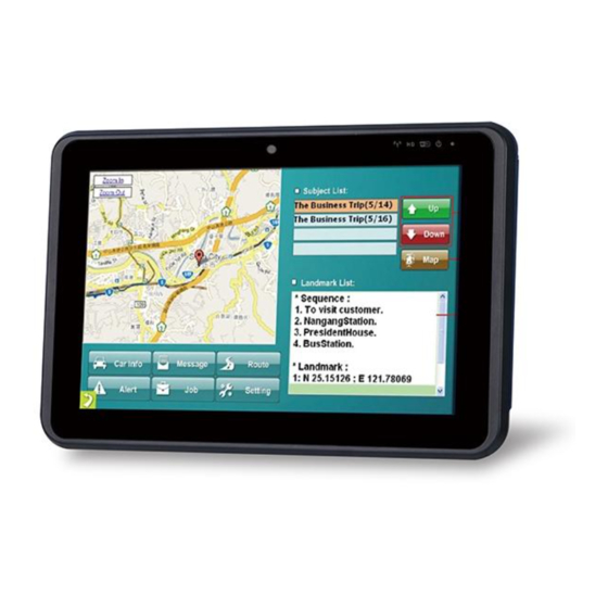
IKARPC-W10A-BT In-vehicle Panel PC recommended to follow the step-by-step procedure to install all of these three drivers/applications. 4.3.2 Usage To launch the application, double click the MobileAP icon on the Windows desktop. The user interface appears as shown in Figure 4-2. The functions are described below. -
Page 44: Figure 4-3: Mobile Ap-Dial Up
IKARPC-W10A-BT In-vehicle Panel PC The Mobile AP also allows the user to make a phone call. To use Mobile AP to make a phone call, tap the Dial up tab in the Mobile AP. Then, the user interface appears as shown in Figure 4-3. -
Page 45: Bios
IKARPC-W10A-BT In-vehicle Panel PC Chapter BIOS Page 35... -
Page 46: Introduction
IKARPC-W10A-BT In-vehicle Panel PC 5.1 Introduction The BIOS is programmed onto the BIOS chip. The BIOS setup program allows changes to certain system settings. This chapter outlines the options that can be changed. NOTE: Some of the BIOS options may vary throughout the life cycle of the product and are subject to change without prior notice. -
Page 47: Getting Help
IKARPC-W10A-BT In-vehicle Panel PC Function Increase the numeric value or make changes Decrease the numeric value or make changes Page Up key Move to the previous page Page Dn key Move to the next page Esc key Main Menu – Quit and not save changes into CMOS... -
Page 48: Main
IKARPC-W10A-BT In-vehicle Panel PC The following sections completely describe the configuration options found in the menu items at the top of the BIOS screen and listed above. 5.2 Main The Main BIOS menu (BIOS Menu 1) appears when the BIOS Setup program is entered. - Page 49 IKARPC-W10A-BT In-vehicle Panel PC Build Date: Date the current BIOS version was made CPU Information The CPU Information lists a brief summary of the CPU. The fields in CPU Information cannot be changed. The items shown in the system overview include: ...
-
Page 50: Advanced
IKARPC-W10A-BT In-vehicle Panel PC 5.3 Advanced Use the Advanced menu (BIOS Menu 2) to configure the CPU and peripheral devices through the following sub-menus: WARNING: Setting the wrong values in the sections below may cause the system to malfunction. Make sure that the settings made are compatible with the hardware. -
Page 51: Acpi Settings
IKARPC-W10A-BT In-vehicle Panel PC 5.3.1 ACPI Settings The ACPI Settings menu (BIOS Menu 3) configures the Advanced Configuration and Power Interface (ACPI) options. Aptio Setup Utility – Copyright (C) 2015 American Megatrends, Inc. Advanced ACPI Settings Select the highest ACPI... -
Page 52: Super Io Configuration
IKARPC-W10A-BT In-vehicle Panel PC 5.3.2 Super IO Configuration Use the Super IO Configuration menu (BIOS Menu 4) to set or change the configurations for the serial ports. Aptio Setup Utility – Copyright (C) 2015 American Megatrends, Inc. Advanced Super IO Configuration... - Page 53 IKARPC-W10A-BT In-vehicle Panel PC 5.3.2.1.1 Serial Port 1 Configuration Serial Port [Enabled] Use the Serial Port option to enable or disable the serial port. Disable the serial port Disabled Enable the serial port Enabled EFAULT Change Settings [Auto] Use the Change Settings option to change the serial port IO port address and interrupt address.
- Page 54 IKARPC-W10A-BT In-vehicle Panel PC 5.3.2.1.2 Serial Port 2 Configuration Serial Port [Enabled] Use the Serial Port option to enable or disable the serial port. Disable the serial port Disabled Enable the serial port Enabled EFAULT Change Settings [Auto] Use the Change Settings option to change the serial port IO port address and interrupt address.
- Page 55 IKARPC-W10A-BT In-vehicle Panel PC 5.3.2.1.3 Serial Port 6 Configuration Serial Port [Enabled] Use the Serial Port option to enable or disable the serial port. Disable the serial port Disabled Enable the serial port Enabled EFAULT Change Settings [Auto] Use the Change Settings option to change the serial port IO port address and interrupt address.
-
Page 56: Hardware Monitor
IKARPC-W10A-BT In-vehicle Panel PC Serial Port I/O port address is 3E0h and the interrupt IO=3E0h; address is IRQ3, 4, 5, 6, 7, 9, 10, 11, 12 IRQ=3, 5, 6, 7, 9, 10, 11, 12 Serial Port I/O port address is 2E0h and the interrupt IO=2E0h;... -
Page 57: Power Management
IKARPC-W10A-BT In-vehicle Panel PC Voltages: +SOC_VCC +V5S +12S +1.5S VCC3V VSB3V VSB5V 5.3.4 Power Management Use the Power Management menu (BIOS Menu 7) to configure the power management function. Aptio Setup Utility – Copyright (C) 2015 American Megatrends, Inc. - Page 58 IKARPC-W10A-BT In-vehicle Panel PC Auto Power On Delay [10 sec] Use the Auto Power On Delay option to set the automatic power-on delay time. Configuration options are listed below. 10 sec EFAULT 30 sec 1 min 5 min ...
-
Page 59: Sms/Rtc Wake Settings
IKARPC-W10A-BT In-vehicle Panel PC 5.3.5 SMS/RTC Wake Settings The SMS/RTC Wake Settings menu (BIOS Menu 8) enables the system to wake at the specified time. Aptio Setup Utility – Copyright (C) 2015 American Megatrends, Inc. Advanced Wake system with SMS... -
Page 60: Serial Port Console Redirection
IKARPC-W10A-BT In-vehicle Panel PC allowing you to enable to disable the system to wake every day at the specified time. Besides, the following options appear with values that can be selected: Wake up every day Wake up date Wake up hour... - Page 61 IKARPC-W10A-BT In-vehicle Panel PC Console Redirection [Disabled] Use Console Redirection option to enable or disable the console redirection function. Disabled the console redirection function Disabled EFAULT Enabled the console redirection function Enabled Terminal Type [ANSI] Use the Terminal Type option to specify the remote terminal type.
- Page 62 IKARPC-W10A-BT In-vehicle Panel PC Parity [None] Use the Parity option to specify the parity bit that can be sent with the data bits for detecting the transmission errors. No parity bit is sent with the data bits. None EFAULT ...
-
Page 63: Cpu Configuration
IKARPC-W10A-BT In-vehicle Panel PC 5.3.7 CPU Configuration Use the CPU Configuration menu (BIOS Menu 10) to view detailed CPU specifications and configure the CPU. Aptio Setup Utility – Copyright (C) 2015 American Megatrends, Inc. Advanced CPU Configuration When enabled, a VMM can utilize the additional Intel(R) Atom(TM) CPU E3826 @ 1.46GHz... - Page 64 IKARPC-W10A-BT In-vehicle Panel PC L2 Cache: Lists the amount of storage space on the L2 cache. L3 Cache: Lists the amount of storage space on the L3 cache. 64-bit: Indicates if 64-bit OS is supported by the CPU.
-
Page 65: Ide Configuration
IKARPC-W10A-BT In-vehicle Panel PC 5.3.8 IDE Configuration Use the IDE Configuration menu (BIOS Menu 11) to change and/or set the configuration of the SATA devices installed in the system. Aptio Setup Utility – Copyright (C) 2015 American Megatrends, Inc. Advanced... -
Page 66: Usb Configuration
IKARPC-W10A-BT In-vehicle Panel PC 5.3.9 USB Configuration Use the USB Configuration menu (BIOS Menu 12) to read USB configuration information and configure the USB settings. Aptio Setup Utility – Copyright (C) 2012 American Megatrends, Inc. Advanced USB Configuration Enables Legacy USB support. -
Page 67: Chipset
IKARPC-W10A-BT In-vehicle Panel PC 5.4 Chipset Use the Chipset menu (BIOS Menu 13) to access the North Bridge and South Bridge configuration menus. WARNING! Setting the wrong values for the Chipset BIOS selections in the Chipset BIOS menu may cause the system to malfunction. -
Page 68: North Bridge Configuration
IKARPC-W10A-BT In-vehicle Panel PC 5.4.1 North Bridge Configuration Use the North Bridge menu (BIOS Menu 14) to configure the north bridge chipset. Aptio Setup Utility – Copyright (C) 2015 American Megatrends, Inc. Chipset > Intel IGD Configuration Config Intel IGD Settings. -
Page 69: Intel Igd Configuration
IKARPC-W10A-BT In-vehicle Panel PC 5.4.1.1 Intel IGD Configuration Use the Intel IGD Configuration submenu (BIOS Menu 15) to configure the graphics settings. Aptio Setup Utility – Copyright (C) 2015 American Megatrends, Inc. Chipset Intel IGD Configuration Select DVMT 5.0 Pre-Allocated (Fixed) -
Page 70: South Bridge Configuration
IKARPC-W10A-BT In-vehicle Panel PC DVMT Total Gfx Mem [MAX] Use the DVMT Total Gfx Mem option to specify the maximum amount of memory that can be allocated as graphics memory. Configuration options are listed below. 128MB 256MB ... -
Page 71: Security
IKARPC-W10A-BT In-vehicle Panel PC Audio Controller [Enabled] Use the Audio Controller option to enable or disable the High Definition Audio controller. The onboard High Definition Audio controller is disabled Disabled onboard High Definition Audio controller Enabled EFAULT automatically detected and enabled ... -
Page 72: Boot
IKARPC-W10A-BT In-vehicle Panel PC Administrator Password Use the Administrator Password to set or change a administrator password. User Password Use the User Password to set or change a user password. 5.6 Boot Use the Boot menu (BIOS Menu 18) to configure system boot options. - Page 73 IKARPC-W10A-BT In-vehicle Panel PC Does not enable the keyboard Number Lock automatically. To use the 10-keys on the keyboard, press the Number Lock key located on the upper left-hand corner of the 10-key pad. The Number Lock LED on the keyboard lights up when the Number Lock is engaged.
-
Page 74: Save & Exit
IKARPC-W10A-BT In-vehicle Panel PC Sets display mode to current. Keep Current 5.7 Save & Exit Use the Save & Exit menu (BIOS Menu 19) to load default BIOS values, optimal failsafe values and to save configuration changes. Aptio Setup Utility – Copyright (C) 2015 American Megatrends, Inc. - Page 75 IKARPC-W10A-BT In-vehicle Panel PC Restore Defaults Use the Restore Defaults option to load the optimal default values for each of the parameters on the Setup menus. F3 key can be used for this operation. Save as User Defaults Use the Save as User Defaults option to save the changes done so far as user defaults.
-
Page 76: Interface Connectors
IKARPC-W10A-BT In-vehicle Panel PC Chapter Interface Connectors Page 66... -
Page 77: Peripheral Interface Connectors
IKARPC-W10A-BT In-vehicle Panel PC 6.1 Peripheral Interface Connectors The motherboard of the IKARPC-W10A-BT comes with a number of peripheral interface connectors and configuration jumpers. The connector locations are shown in Figure 6-1 and Figure 6-2. The Pin 1 locations of the on-board connectors are also indicated in the diagrams below. -
Page 78: Internal Peripheral Connectors
Internal peripheral connectors are found on the motherboard and are only accessible when the motherboard is outside of the chassis. The table below shows a list of the peripheral interface connectors on the IKARPC-W10A-BT motherboard. Pinouts of these connectors can be found in the following sections. -
Page 79: Battery Connector (Bt1)
IKARPC-W10A-BT In-vehicle Panel PC Connector Type Label Speaker connector 2-pin wafer JSP1 Touch panel connector 6-pin FPC TOUCH1 Table 6-1: Peripheral Interface Connectors 6.2.1 Battery Connector (BT1) PIN NO. DESCRIPTION VBATT Table 6-2: Battery Connector (BT1) Pinouts 6.2.2 BIOS Flash Connector (JSPI1) PIN NO. -
Page 80: Clear Cmos Connector (C_Cmos1)
IKARPC-W10A-BT In-vehicle Panel PC 6.2.4 Clear CMOS Connector (C_CMOS1) PIN NO. DESCRIPTION RTC_RST# Table 6-5: Clear CMOS Connector (C_CMOS1) Pinouts 6.2.5 Debug Port Connector (DBG_PORT1) PIN NO. DESCRIPTION CLK33M RESET FRAME LAD0 LAD1 LAD2 LAD3 SERIRQ VCC3 Table 6-6: Debug Port Connector (DBG_PORT1) Pinouts 6.2.6 LED Connector (JLED1) -
Page 81: Lvds Connector (Lvds1)
IKARPC-W10A-BT In-vehicle Panel PC WIFI_LED HDD_LED Table 6-7: LED Connector (JLED1) Pinouts 6.2.7 LVDS Connector (LVDS1) PIN NO. DESCRIPTION PIN NO. DESCRIPTION VLCD_VCOM LCM_RIN3+ VLCD_VDD LCM_RIN0- LCM_RIN0+ VCC_LCD_AVDD LCM_RIN1- LCM_LEDK LCM_RIN1+ LCM_LEDK LCM_RIN2- LCM_RIN2+ VLCD_VGL LCM_CLK- LCM_CLK+ VLCD_VGH LCM_LEDA LCM_RIN3-... -
Page 82: Pcie Mini Socket For 3.75G Module (Mini_Pcie1)
IKARPC-W10A-BT In-vehicle Panel PC JMIC Table 6-9: Microphone Connector (JMIC1) Pinouts 6.2.9 PCIe Mini Socket for 3.75G Module (MINI_PCIE1) This socket supports USB interface only and voice function. PIN NO. DESCRIPTION PIN NO. DESCRIPTION VCC3 VCC1.5 SIM_VCC SIM_CIO SIM_CLK SIM_RST VCC3 VCC1.5... -
Page 83: Pcie Mini Socket For Wireless Module (Mini_Pcie2)
IKARPC-W10A-BT In-vehicle Panel PC PIN NO. DESCRIPTION PIN NO. DESCRIPTION VCC3 Table 6-10: PCIe Mini Socket for 3.75G Module (MINI_PCIE1) Pinouts 6.2.10 PCIe Mini Socket for Wireless Module (MINI_PCIE2) This socket supports USB interface and PCIe interface. PIN NO. DESCRIPTION PIN NO. -
Page 84: Pcie Mini Socket (Mini_Pcie3)
IKARPC-W10A-BT In-vehicle Panel PC PIN NO. DESCRIPTION PIN NO. DESCRIPTION VCC3 Table 6-11: PCIe Mini Socket for Wireless Module (MINI_PCIE2) Pinouts 6.2.11 PCIe Mini Socket (MINI_PCIE3) This socket supports USB interface and PCIe interface. Capture cards or other PCIe Mini modules can be installed into this socket. -
Page 85: Programming Connector (Jmcu1)
IKARPC-W10A-BT In-vehicle Panel PC PIN NO. DESCRIPTION PIN NO. DESCRIPTION VCC3 Table 6-12: PCIe Mini Socket (MINI_PCIE3) Pinouts 6.2.12 Programming Connector (JMCU1) PIN NO. DESCRIPTION MCLR VCC5 ICSP_CLK ICSP_DAT Table 6-13: Programming Connector (JMCU1) Pinouts 6.2.13 Programming Connector (JOBD1) PIN NO. -
Page 86: Touch Panel Connector (Touch1)
IKARPC-W10A-BT In-vehicle Panel PC 6.2.15 Touch Panel Connector (TOUCH1) PIN NO. DESCRIPTION USB+ USB- Table 6-16: Touch Panel Connector (TOUCH1) Pinouts Page 76... -
Page 87: A Regulatory Compliance
IKARPC-W10A-BT In-vehicle Panel PC Appendix Regulatory Compliance Page 77... - Page 88 IKARPC-W10A-BT In-vehicle Panel PC DECLARATION OF CONFORMITY This equipment is in conformity with the following EU directives: EMC Directive 2004/108/EC Low-Voltage Directive 2006/95/EC RoHS II Directive 2011/65/EU Ecodesign Directive 2009/125/EC If the user modifies and/or install other devices in the equipment, the CE conformity declaration may no longer apply.
- Page 89 IKARPC-W10A-BT In-vehicle Panel PC Español [Spanish] IEI Integration Corp declara que el equipo cumple con los requisitos esenciales y cualesquiera otras disposiciones aplicables o exigibles de la Directiva 1999/5/CE. Ελληνική [Greek] IEI Integration Corp ΔΗΛΩΝΕΙ ΟΤΙ ΕΞΟΠΛΙΣΜΟΣ ΣΥΜΜΟΡΦΩΝΕΤΑΙ ΠΡΟΣ ΤΙΣ...
- Page 90 IKARPC-W10A-BT In-vehicle Panel PC Româna [Romanian] IEI Integration Corp declară că acest echipament este in conformitate cu cerinţele esenţiale şi cu celelalte prevederi relevante ale Directivei 1999/5/CE. Slovensko [Slovenian] IEI Integration Corp izjavlja, da je ta opreme v skladu z bistvenimi zahtevami in ostalimi relevantnimi določili direktive 1999/5/ES.
- Page 91 IKARPC-W10A-BT In-vehicle Panel PC FCC WARNING This equipment complies with Part 15 of the FCC Rules. Operation is subject to the following two conditions: This device may not cause harmful interference, and This device must accept any interference received, including interference ...
-
Page 92: Bobd-Ii Reader Command
IKARPC-W10A-BT In-vehicle Panel PC Appendix OBD-II Reader Command Page 82... -
Page 93: Select A Chip Initial Mode: Update F/W Or Run F/W
IKARPC-W10A-BT In-vehicle Panel PC B.1 Select a Chip Initial Mode: UpDate F/W or RUN F/W AP sends query F/W receives query Enter Boot Mode Enter RUN Mode B.2 Boot Mode Launch AP: P1618QP (Pic18F Bootloader ) ... - Page 94 IKARPC-W10A-BT In-vehicle Panel PC F/W returns (after receiving query) Select a mode to send Tele mode response CAN S mode response Enter Tele mode to respond Enter CAN S mode to respond Page 84...
-
Page 95: Into Can_Standard V2.2.B (Can Standard)
IKARPC-W10A-BT In-vehicle Panel PC B.4 Into CAN_Standard V2.2.B (CAN standard) AP sends query F/W receives query 0x0A 0x0D Sent by xxx Baud 0x00 Set CAN Reserved baud 0x00 TxIDE RTR ID(1 ID(2 ID(3 ID(4 Set to Reserved B0 B1... - Page 96 IKARPC-W10A-BT In-vehicle Panel PC complete 0x0A Menu setup complete TxID ID(1) ID(2) ID(3) ID(4) 0x0A Read query setup Read menu D(1) D(2) D(3) D(4) 1ID( 1ID( 1ID( 1ID( 2ID( 2ID( 2ID( 2ID( D(1) D(2) D(3) D(4) setup RxID 0x0A 1ID(...
-
Page 97: Into Telematics (Vehicel Information)
IKARPC-W10A-BT In-vehicle Panel PC B.5 Into Telematics (Vehicel Information) F/W:Telematics AP: Telematics V1.005 AP sends query F/W receives query Scan all Scan all Scan OBD-II Scan J1939 Scan FMS OBD-II input PID-1 OBD-II input PID-2 OBD-II... - Page 98 IKARPC-W10A-BT In-vehicle Panel PC Reserved J1939 input PSPF FMS input PSPF Version F/W returns (after receiving query) device is scanned Devices Scanned Page 88...
- Page 99 IKARPC-W10A-BT In-vehicle Panel PC OBD packet format (ASCII code) OBD packet has five different format, they are: 1. CAN 11bits 250 2. CAN 29bits 250 3. CAN 11bits 500 4. CAN 29bits 500 5.Scanning Each format has its input code, they are:...
- Page 100 IKARPC-W10A-BT In-vehicle Panel PC Byte 4 define as A. (same with the PID code table on Wikipedia) Byte 5 define as B. (same with the PID code table on Wikipedia) Byte 6 define as C. (same with the PID code table on Wikipedia) Byte 7 define as D.
-
Page 101: C Watchdog Timer
IKARPC-W10A-BT In-vehicle Panel PC Appendix Watchdog Timer Page 91... - Page 102 IKARPC-W10A-BT In-vehicle Panel PC NOTE: The following discussion applies to DOS. Contact IEI support or visit the IEI website for drivers for other operating systems. The Watchdog Timer is a hardware-based timer that attempts to restart the system when it stops working.
- Page 103 IKARPC-W10A-BT In-vehicle Panel PC NOTE: The Watchdog Timer is activated through software. The software application that activates the Watchdog Timer must also deactivate it when closed. If the Watchdog Timer is not deactivated, the system will automatically restart after the Timer has finished its countdown.
-
Page 104: D Hazardous Materials Disclosure
IKARPC-W10A-BT In-vehicle Panel PC Appendix Hazardous Materials Disclosure Page 94... -
Page 105: Hazardous Materials Disclosure Table For Ipb Products Certified As Rohs Compliant Under 2002/95/Ec Without Mercury
IKARPC-W10A-BT In-vehicle Panel PC D.1 Hazardous Materials Disclosure Table for IPB Products Certified as RoHS Compliant Under 2002/95/EC Without Mercury The details provided in this appendix are to ensure that the product is compliant with the Peoples Republic of China (China) RoHS standards. The table below acknowledges the presences of small quantities of certain materials in the product, and is applicable to China RoHS only. - Page 106 IKARPC-W10A-BT In-vehicle Panel PC Part Name Toxic or Hazardous Substances and Elements Lead Mercury Cadmium Hexavalent Polybrominated Polybrominated (Pb) (Hg) (Cd) Chromium Biphenyls Diphenyl (CR(VI)) (PBB) Ethers (PBDE) Housing Display Printed Circuit Board Metal Fasteners Cable Assembly Fan Assembly Power Supply...
- Page 107 IKARPC-W10A-BT In-vehicle Panel PC 此附件旨在确保本产品符合中国 RoHS 标准。以下表格标示此产品中某有毒物质的含量符 合中国 RoHS 标准规定的限量要求。 本产品上会附有”环境友好使用期限”的标签,此期限是估算这些物质”不会有泄漏或突变”的 年限。本产品可能包含有较短的环境友好使用期限的可替换元件,像是电池或灯管,这些元 件将会单独标示出来。 部件名称 有毒有害物质或元素 铅 汞 镉 六价铬 多溴联苯 多溴二苯 醚 (Pb) (Hg) (Cd) (CR(VI)) (PBB) (PBDE) 壳体 显示 印刷电路板 金属螺帽 电缆组装 风扇组装 电力供应组装 电池 O: 表示该有毒有害物质在该部件所有物质材料中的含量均在 SJ/T11363-2006 标准规定的限量要求以下。...
Need help?
Do you have a question about the IKARPC-W10A-BT and is the answer not in the manual?
Questions and answers