Table of Contents
Advertisement
Quick Links
Advertisement
Table of Contents

Related Manuals for IEI Technology IOVU-752S


Summary of Contents for IEI Technology IOVU-752S
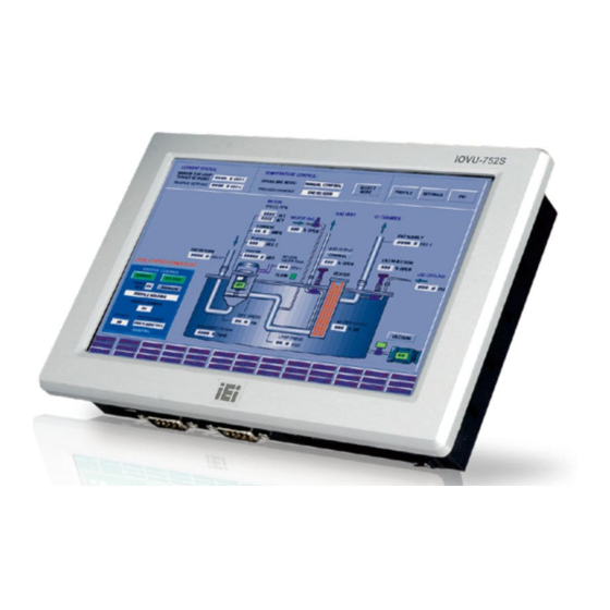
- Page 1 IOVU-752S Panel PC IEI Technology Corp. MODEL: IOVU-752S RISC-Based Panel PC, 7" Touch Screen, 667 MHz Samsung ARM11 S3C6410, PoE, USB, SD, RS-232/422/485, IP 64 Compliant Front Panel, RoHS Compliant User Manual Page i Rev. 1.00 – 11 January, 2012...
- Page 2 IOVU-752S Panel PC Revision Date Version Changes 11 January, 2012 1.00 Initial release Page ii...
- Page 3 IOVU-752S Panel PC Copyright COPYRIGHT NOTICE The information in this document is subject to change without prior notice in order to improve reliability, design and function and does not represent a commitment on the part of the manufacturer. In no event will the manufacturer be liable for direct, indirect, special, incidental, or consequential damages arising out of the use or inability to use the product or documentation, even if advised of the possibility of such damages.
-
Page 4: Table Of Contents
IOVU-752S Panel PC Table of Contents 1 INTRODUCTION......................1 1.1 O ........................2 VERVIEW 1.2 B ........................2 ENEFITS 1.3 F ........................3 EATURES 1.4 F ......................3 RONT ANEL 1.5 C ....................4 ONNECTOR ANEL 1.6 I ....................4... - Page 5 IOVU-752S Panel PC 3.4.1 Wall Mounting....................22 3.4.2 Panel Mounting....................25 3.4.3 Arm Mounting ....................27 3.4.4 Stand Mounting ....................28 3.5 S ........................ 29 OFTWARE A CERTIFICATIONS ....................30 A.1 R HS C ....................31 OMPLIANT A.2 IP 64 C ................
- Page 6 Figure 1-1: IOVU-752S........................2 Figure 1-2: IOVU-752S Front Panel ....................3 Figure 1-3: IOVU-752S Peripheral Connectors ................4 Figure 1-4: IOVU-752S Physical Dimensions (millimeters) ............5 Figure 3-1: Rear Panel Retention Screws ..................14 Figure 3-2: SD Card Installation ....................14 Figure 3-3: IOVU-752S Peripheral Connectors ................15 Figure 3-4: Power Terminal Block....................16...
- Page 7 IOVU-752S Panel PC List of Tables Table 1-1: Technical Specifications....................7 Table 2-1: Package List Contents ....................10 Table 2-2: Optional Items......................11 Table 3-1: External Interface Connectors...................15 Table 3-2: 9 V~30 V Power Connector Pinouts................16 Table 3-3: Ethernet Connector Pinouts ..................17 Table 3-4: Ethernet Connector LEDs ..................18 Table 3-5: RS-232 Pinouts ......................18...
-
Page 8: Introduction
IOVU-752S Panel PC Chapter Introduction Page 1... -
Page 9: Overview
Output capabilities are provided through RS-232/422/485 ports, network port and USB ports. The IOVU-752S is an extremely low power Panel PC. The system is fanless, which allows quiet and reliable operation. The IOVU-752S is preinstalled with Windows® CE 6.0 OS to provide rich application development support and connectivity to network and I/O devices. -
Page 10: Features
One SD card socket Two 1.5 Watt speakers 9V~30V DC input IP 64 compliant front panel RoHS compliant 1.4 Front Panel The IOVU-752S front panel (Figure 1-2) comprises a 7" TFT WVGA color touch screen LCD. Figure 1-2: IOVU-752S Front Panel Page 3... -
Page 11: Connector Panel
1.5 Connector Panel The external peripheral interface connectors are located on the bottom panel of the IOVU-752S . The peripheral interface connectors are shown in Figure 1-3. Figure 1-3: IOVU-752S Peripheral Connectors External peripheral interface connectors on the IOVU-752S include:... -
Page 12: Dimensions
IOVU-752S Panel PC 1.7 Dimensions The physical dimensions of the IOVU-752S are shown in Figure 1-4: Figure 1-4: IOVU-752S Physical Dimensions (millimeters) Page 5... -
Page 13: Technical Specifications
IOVU-752S Panel PC 1.8 Technical Specifications The IOVU-752S technical specifications are listed in Table 1-1. Specifications System 667 MHz Samsung ARM11 S3C6410 processor 128 MB Nand Flash Memory 256 MB DDR2 Windows® CE 6.0 preinstalled Operating System Battery backup RTC Real-time Clock Software programmable supports 1~255 sec. -
Page 14: Certifications
Physical Dimensions IP 64 compliant front panel Ingress Protection Table 1-1: Technical Specifications 1.9 Certifications The IOVU-752S complies with the following international standards: RoHS IP 64 For a more detailed description of these standards, please refer to Appendix A. Page 7... -
Page 15: Unpacking
IOVU-752S Panel PC Chapter Unpacking Page 8... -
Page 16: Anti-Static Precautions
When the IOVU-752S is unpacked, please do the following: Follow the anti-static precautions outlined in Section 2.1. Make sure the packing box is facing upwards so the IOVU-752S does not fall out of the box. Make sure all the components shown in Section 2.3 are present. -
Page 17: Unpacking Checklist
If some of the components listed in the checklist below are missing, please do not proceed with the installation. Contact the IEI reseller or vendor you purchased the IOVU-752S from or contact an IEI sales representative directly. To contact an IEI sales representative, please send an email to sales@iei.com.tw. -
Page 18: Optional Items
IOVU-752S Panel PC 2.4 Optional Items Item and Part Number Image Panel mount kit (P/N: ALFPK-08) VESA 75 wall mount kit (P/N: AFLWK-07) LCD monitor/PPC arm kit, load capacity of 3kg~7kg (P/N: ARM-11-RS) LCD monitor/PPC stand kit for VESA 75, up to 5kg... -
Page 19: Installation
IOVU-752S Panel PC Chapter Installation Page 12... -
Page 20: Installation Precautions
Electric shock and personal injury might occur if the rear panel of the IOVU-752S is opened while the power cord is still connected to an electrical outlet. -
Page 21: Sd Card Installation
IOVU-752S Panel PC 3.2 SD Card Installation The IOVU-752S supports an SD card. Follow the steps below to install an SD card. Remove the rear panel by removing the 10 retention screws from the rear panel Step 1: (Figure 3-1). -
Page 22: External Peripheral Interface Connectors
IOVU-752S Panel PC 3.3 External Peripheral Interface Connectors Table 3-1 lists the external interface connectors on the IOVU-752S. Detailed descriptions of the connectors can be found following the table. Connector Type 9V~30V DC power jack DC jack 9V~30V DC power terminal block... -
Page 23: 30 V Dc Terminal Block
To connect a LAN cable with an RJ-45 connector, please follow the instructions below. Align the connectors. Align the RJ-45 connector on the LAN cable with one of Step 1: the RJ-45 connectors on the IOVU-752S. See Figure 3-5. Page 16... -
Page 24: Figure 3-5: Lan Connection
IOVU-752S Panel PC Figure 3-5: LAN Connection Insert the LAN cable RJ-45 connector. Once aligned, gently insert the LAN Step 2: cable RJ-45 connector into the on-board RJ-45 connector. Step 0: The Ethernet connector pinouts are shown below. DESCRIPTION TPT+... -
Page 25: Serial Interfaces
IOVU-752S Panel PC The RJ-45 Ethernet connector has two status LEDs, one green and one yellow. The green LED indicates activity on the port and the yellow LED indicates the port is linked (Table 3-4). SPEED LED LINK LED Status... -
Page 26: Rs-232/422/485 Serial Interface Pinouts
IOVU-752S Panel PC 3.3.3.2 RS-232/422/485 Serial Interface Pinouts Pinouts for the RS-232/422/485 serial port are shown below. RS-232 RS-422 RS-485 DATA- DATA+ Table 3-6: Serial Port Pinouts Figure 3–7: Serial Port Pinouts To select RS-232, RS-422, or RS-485 mode, please follow the directions below. -
Page 27: Connecting The Serial Port
Step 3: Step 0: 3.3.3.3 Connecting the Serial Port Follow the steps below to connect a serial device to the IOVU-752S. Insert the serial connector. Insert the DB-9 connector of a serial device into Step 1: the DB-9 connector on the external peripheral interface. See Figure 3-9. -
Page 28: Usb Connectors
The external USB Series "A" receptacle connector provides easier and quicker access to external USB devices. Follow the steps below to connect USB devices to the IOVU-752S. Insert a USB Series "A" plug. Insert the USB Series "A" plug of a device into Step 1: the USB Series "A"... -
Page 29: Mounting The System
Stand mounting The four mounting methods are described below. 3.4.1 Wall Mounting To mount the IOVU-752S onto the wall, please follow the steps below. Select the location on the wall for the wall-mounting bracket. Step 1: Carefully mark the locations of the four screw holes in the bracket on the wall. -
Page 30: Figure 3-11: Wall-Mounting Bracket
Insert the four monitor mounting screws provided in the wall mounting kit into the Step 6: four screw holes on the real panel of the IOVU-752S and tighten until the screw shank is secured against the rear panel (Figure 3-12). -
Page 31: Figure 3-12: Chassis Support Screws
IOVU-752S Panel PC Figure 3-12: Chassis Support Screws Secure the panel PC by fastening the retention screw of the wall-mounting Step 9: bracket (Figure 3-13). Figure 3-13: Secure the IOVU-752S Page 24... -
Page 32: Panel Mounting
Cut out a section from the panel that corresponds to the rear panel dimensions Step 2: of the IOVU-752S. Take care that the panel section that is cut out is smaller than the overall size of the frame that surrounds the IOVU-752S but just large enough for the rear panel of the IOVU-752S to fit through (see Figure 3-14). -
Page 33: Figure 3-15: Panel Mounting Clamps
IOVU-752S Panel PC Insert the panel mounting clamps into the pre-formed holes along the edges of Step 4: the chassis, behind the frame. Figure 3-15: Panel Mounting Clamps Tighten the screws that pass through the panel mounting clamps until the plastic Step 5: caps at the front of all the screws are firmly secured to the panel (Figure 3-16). -
Page 34: Arm Mounting
3.4.3 Arm Mounting The IOVU-752S is VESA (Video Electronics Standards Association) compliant and can be mounted on an arm with a 75 mm interface pad. To mount the IOVU-752S on an arm, please follow the steps below. The arm is a separately purchased item. Please correctly mount the arm onto Step 1: the surface it uses as a base. -
Page 35: Stand Mounting
The monitor stand mounting plate has a matching VESA hole pattern. To mount the IOVU-752S onto a stand, please follow the steps below. Line up the threaded holes on the system rear panel with the screw holes on the Step 1: monitor stand mounting plate. -
Page 36: Software
For information about configuring the operating system, adding remote management tools or additional software and drivers, refer to the user manuals on IEI IOVU Utility CD that came with the IOVU-752S. The IOVU includes the following software: Standard Windows®... -
Page 37: A Certifications
IOVU-752S Panel PC Appendix Certifications Page 30... -
Page 38: Rohs Compliant
A.2 IP 64 Compliant Front Panel The front panels on the IOVU-752S models in the IOVU series have an ingress protection rating (IP) of 64, IP 64 or greater. The front panels are protected from dust particles and splashed water. -
Page 39: B Safety Precautions
IOVU-752S Panel PC Appendix Safety Precautions Page 32... -
Page 40: Safety Precautions
Do not apply voltage levels that exceed the specified voltage range. Doing so may cause fire and/or an electrical shock. Electric shocks can occur if the IOVU-752S chassis is opened when the IOVU-752S is running. Do not drop or insert any objects into the ventilation openings of the IOVU-752S. -
Page 41: Anti-Static Precautions
Electrostatic discharge (ESD) can cause serious damage to electronic components, including the IOVU-752S. Dry climates are especially susceptible to ESD. It is therefore critical that whenever the IOVU-752S is opened and any of the electrical components are handled, the following anti-static precautions are strictly adhered to. -
Page 42: Product Disposal
Please follow the national guidelines for electrical and electronic product disposal. B.2 Maintenance and Cleaning Precautions When maintaining or cleaning the IOVU-752S, please follow the guidelines below. B.2.1 Maintenance and Cleaning Prior to cleaning any part or component of the IOVU-752S please read the details below. Page 35... -
Page 43: Cleaning Tools
In such case, the product will be explicitly mentioned in the cleaning tips. Below is a list of items to use when cleaning the IOVU-752S. C loth – Although paper towels or tissues can be used, a soft, clean piece of cloth is recommended when cleaning the IOVU-752S. -
Page 44: Fcc Precautions
IOVU-752S Panel PC B.3 FCC Precautions WARNING: This device complies with Part 15 of the FCC Rules. Operation is subject to the following two conditions: (1) this device may not cause harmful interference, and(2) this device must accept any interference received, including interference that may cause undesired operation. -
Page 45: C Hazardous Materials Disclosure
IOVU-752S Panel PC Appendix Hazardous Materials Disclosure Page 38... -
Page 46: Hazardous Materials Disclosure Table For Ipb Products Certified As Rohs Compliant Under 2002/95/Ec Without Mercury
IOVU-752S Panel PC C.1 Hazardous Materials Disclosure Table for IPB Products Certified as RoHS Compliant Under 2002/95/EC Without Mercury The details provided in this appendix are to ensure that the product is compliant with the Peoples Republic of China (China) RoHS standards. The table below acknowledges the presences of small quantities of certain materials in the product, and is applicable to China RoHS only. - Page 47 IOVU-752S Panel PC Part Name Toxic or Hazardous Substances and Elements Lead Mercury Cadmium Hexavalent Polybrominated Polybrominated (Pb) (Hg) (Cd) Chromium Biphenyls Diphenyl (CR(VI)) (PBB) Ethers (PBDE) Housing Display Printed Circuit Board Metal Fasteners Cable Assembly Fan Assembly Power Supply...
- Page 48 IOVU-752S Panel PC 此附件旨在确保本产品符合中国 RoHS 标准。以下表格标示此产品中某有毒物质的含量符 合中国 RoHS 标准规定的限量要求。 本产品上会附有”环境友好使用期限”的标签,此期限是估算这些物质”不会有泄漏或突变”的 年限。本产品可能包含有较短的环境友好使用期限的可替换元件,像是电池或灯管,这些元 件将会单独标示出来。 部件名称 有毒有害物质或元素 铅 汞 镉 六价铬 多溴联苯 多溴二苯 醚 (Pb) (Hg) (Cd) (CR(VI)) (PBB) (PBDE) 壳体 显示 印刷电路板 金属螺帽 电缆组装 风扇组装 电力供应组装 电池 O: 表示该有毒有害物质在该部件所有物质材料中的含量均在 SJ/T11363-2006 标准规定的限量要求以下。 X: 表示该有毒有害物质至少在该部件的某一均质材料中的含量超出 SJ/T11363-2006 标准规定的限量要求。...
Need help?
Do you have a question about the IOVU-752S and is the answer not in the manual?
Questions and answers