Table of Contents
Advertisement
Quick Links
Advertisement
Table of Contents

Related Manuals for Circutor URBAN M11


Summary of Contents for Circutor URBAN M11
-
Page 1: 4�3�- Connection
Outdoor charging posts URBAN Series INSTRUCTION MANUAL (M177B01-03-17A) - Page 2 URBAN Instruction Manual...
-
Page 3: Safety Precautions
CIRCUTOR, SA reserves the right to modify features or the product manual without prior notifi cation. DISCLAIMER CIRCUTOR, SA reserves the right to make modifi cations to the device or the unit specifi ca- tions set out in this instruction manual without prior notice. -
Page 4: Table Of Contents
8�1�- CLIENT ����������������������������������������������������������������������������������������������������������������������������������������������������23 8�1�1�- PLUG SECTION ��������������������������������������������������������������������������������������������������������������������������������23 9�- TECHNICAL FEATURES ��������������������������������������������������������������������������������������������������������������������������������25 9�1�- URBAN M11, URBAN T11, URBAN M12, URBAN T12, URBAN T12-MIX �������������������������������������������25 9�2�- URBAN M21, URBAN T21, URBAN M22, URBAN T22, URBAN T22, URBAN T24-MIX ���������������������26 10�- TECHNICAL SERVICE ����������������������������������������������������������������������������������������������������������������������������������28 11�- WARRANTY ���������������������������������������������������������������������������������������������������������������������������������������������������28... -
Page 5: Revision Log
URBAN REVISION LOG Table 1: Revision log� Date Revision Description 10/17 M177B01-03-17A Initial Version SYMBOLS Table 2: Symbols� Symbol Description In compliance with the corresponding European directive. AC current Note: The images of the device are for illustrative purposes only and might differ from the orig- inal device. -
Page 6: 1�- Important Safety Information
● Read all the instructions before using and configuring this product. ● Do not use this device for anything other than electric vehicle charging. ● Do not modify this device. If modified, CIRCUTOR will reject all responsibility and the warran- ty will be void. -
Page 7: 2�- Features
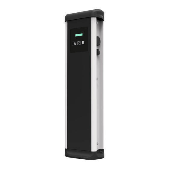
URBAN 2�- FEATURES Main features of the device, Figure 1 Socket A LED Socket B LED Beacon Beacon Proximity Card Display Reader Figure 1: Main features of the device� Note : Charge Point may not include elements of electrical protection. Display: Information about the status of the connectors and detailed data as kWh and duration time. -
Page 8: 3�- How To Use
URBAN 3�- HOW TO USE IT? 3.1.- START CHARGING 1�- The first step is to show the proximity card to the reader Once done, the Led Beacon turns Blue and the Display shows the following sequence of mes- sages: If the proximity card reader is disabled, charge transaction starts automatically when a vehicle is detected. -
Page 9: 3�2�- Stop Charging
URBAN 3.2.- STOP CHARGING 1�- The first step is to show the proximity card to the reader Once done, the Led Beacon turns Green and the Display shows the summary of the charge transaction: If the proximity card reader is disabled, charge transaction stops automatically when a cable is disconnected from the vehicle. -
Page 10: 4�- How To Configure
Before proceeding with the configuration, make sure all the following is ready: Computer running Microsoft Windows, at least Windows XP. UTP Cable (Crossover recommended) IPSetup.exe (Software provided by Circutor) 4.3.- CONNECTION Charge Point is delivered with default network setting of “DHCP enabled”. -
Page 11: 4�4�- Setup Web Page
URBAN Figure 2:IP Setup� 4.4.- SETUP WEB PAGE Setup web page allows managing networking setup, modem 3G setup, upgrading the device and other options. To access the setup web page, open a web browser and enter the following address: http://”IP ADDRESS”/html/setup�html Figure 3: Setup web page Instruction Manual... -
Page 12: 4�4�1�- Network Setup
URBAN 4�4�1�- NETWORK SETUP This section provides basic configuration of the network parameters, Figure 4 Figure 4: Network setup� Host name: Name of the device on the network DHCP: Enable or disable the IP address assignment by a DHCP server DHCP Client ID: Client ID associated to the DHCP Server (If available) Address: IP address assigned to the charge point Netmask: Netmask of the network... -
Page 13: 4�4�3�- Public Address Manager
URBAN 4�4�3�- PUBLIC ADDRESS MANAGER This section is for integrations and allows setting the IP address to establish connection be- tween the Charge Point and the Central System. Figure 6: Public address manger Address type: - Local address: select this option if the OCPP central system is connected to the same private network than the charge point is already connected. -
Page 14: 4�4�6�- Dynamic Dns Setup
URBAN Primary NTP Server and Secondary NTP Server: Synchronize the time through internet automatically. Time zone: Select the regional device time according to the location. Time: Current date and time of the device. 4�4�6�- DYNAMIC DNS SETUP Dynamic DNS is a system that updates in real-time the public IP address assigned to a domain name server. -
Page 15: 4�4�8�- Information
URBAN 4�4�8�- INFORMATION This section provides basic information about the device. Figure 11: Information� MAC: Identifier of the network card of the device. Version Upgrade: Version of the firmware currently installed and link to the upgrade web page, see “4.4.8.1.- System upgrade”. Powerstudio version: Engine version of PowerStudio. -
Page 16: 5�- 3G Communications
URBAN 5�- 3G COMMUNICATIONS 5.1.- PARAMETERS Access “ ” section of the “ ” . 4.4.2.- MODEM SETUP (Only 3G models) 4.4.- SETUP WEB PAGE Once SIM card is inserted on the embedded 3G modem, enter the following parameters: APN (Access Point Name) User Password Figure 13: Modem setup�... -
Page 17: 5�3�- Connection Status
URBAN 5.3.- CONNECTION STATUS When the 3G connection is successful, following message appears on the web page of modem status. Direct link: http://”IP ADDRESS”/html/modem-status�html Figure 16: Status� Connection: - 3G communications status. - Data access protocol used. - Signal and coverage. IP Address: Public IP assigned by the SIM card network operator. -
Page 18: 6�- Integrations
URBAN 6�- INTEGRATIONS 6.1.- BEFORE STARTING Following items must be taken into account before proceeding in order to ensure proper per- formance: ● If 3G modem is enabled, select Embedded Modem within Public Address Manager sec- tion: Direct link: http://”IP ADDRESS”/html/setup�html Figure 17: Public Address Manager�... -
Page 19: 7�- Ocpp 1�5
URBAN 7�- OCPP 1�5 7.1.- MANAGEMENT SYSTEM (CS) Allows the Charge Point to know where the central system is hosted to notify all the requests. Following fields are mandatory to complete: Figure 19:Management System (CS)� Host URL: URL address of the central system. User and Password: Authentication for central system. -
Page 20: 7�3�- Ocpp Settings
URBAN 7.3.- OCPP SETTINGS Select proper values according to OCPP Central System parameters. Figure 21:OCPP Settings� Use local white-list: - Yes: local list of authorized users enabled. - No: local list of authorized users disabled. Authorization check order: - White-List first: ID authorization has first place on the local white-list. If the user does not exist locally, then in second place backend is asked to obtain the authorization. - Page 21 URBAN Use OCPP time synchronization: - Yes: Synchronization of date and time enabled. - No: Synchronization of date and time disabled. Compress OCPP messages: - Yes: enabled. - No: disabled. Energy for Start/Stop transaction: - Partial: Consumed value of energy by the vehicle sent between start and stop. - Total: Existing value of the total accumulated energy of the meter, is sent between start and stop.
-
Page 22: 7�4�- Finalizing
URBAN Active Power in Metervalues: - Yes: Send power (Power.Active.Import) and energy (Energy.Active.Import.Register) consumed by the vehicle within meter values requests. -No: Only energy consumed is sent within meter values request. Heartbeat interval: Interval between Heartbeats (in seconds) for the Central System. Connection timeout: Timeout (in seconds) before connecting to the Central System. -
Page 23: 8�- Monitoring
URBAN 8�- MONITORING 8.1.- CLIENT Charge Point status can be monitored using a software provided by Circutor: Figure 23:Software� 8�1�1�- PLUG SECTION This section describes the plug status and other useful information. Figure 24: Plug section� Status: Plug status: : Plug available,... - Page 24 URBAN Car conected: Vehicle connection status: Car connected, Car not connected. Connector lock: Connector lock status: Locked plug, Unlocked plug. Reserved: Reservation status: 0: No reservation, : Reserved. Charge: - Remote start: Starts a charge from remotely point. - Remote stop: Stop charging in progress. - Paused: Pauses charging in progress.
-
Page 25: 9�- Technical Features
URBAN 9�- TECHNICAL FEATURES 9.1.- URBAN M11, URBAN T11, URBAN M12, URBAN T12, URBAN T12-MIX Electrical data T12-MIX Power supply 1P+N+PE 3P+N+PE 1P+N+PE 3P+N+PE Input voltage 230V~± 10% 400V~± 10% 230V~±10% 400V~±10% Input Current 35 A 67 A 51 A... -
Page 26: 9�2�- Urban M21, Urban T21, Urban M22, Urban T22, Urban T22, Urban T24-Mix
URBAN Standards Electric vehicle conductive charging system - Part 1: General requirements IEC 61851-1: 2010 Electric vehicle conductive charging system -- Part 22: AC electric vehicle IEC 61851-22: 2001 charging station Plugs, socket-outlets, vehicle connectors and vehicle inlets - Conductive IEC 62196-1: 2014 charging of electric vehicles - Part 1: General requirements Plugs, socket-outlets, vehicle connectors and vehicle inlets - Conductive... - Page 27 URBAN Environmental Conditions Operating temperature -5ºC ... +45ºC Operating temperature with Low -30ºC ... +45ºC temperature kit Storage temperature -20ºC ... +60ºC Operating humidity 5% ... 95% Non-condensing Mechanical Data Enclosure rating IP54 / IK10 Enclosure material Aluminium & ABS Enclosure door Frontal key locked door Net weight...
-
Page 28: 10�- Technical Service
• CIRCUTOR accepts no liability due to the possible damage to the unit or other parts of the installation, nor will it cover any possible sanctions derived from a pos- sible failure, improper installation or “improper usage”... -
Page 29: 12�- Ce Certificate
URBAN 12�- CE CERTIFICATE Instruction Manual... - Page 30 CIRCUTOR, SA Vial Sant Jordi, s/n 08232 - Viladecavalls (Barcelona) Tel: (+34) 93 745 29 00 - Fax: (+34) 93 745 29 14 www.circutor.com central@circutor.com...
Need help?
Do you have a question about the URBAN M11 and is the answer not in the manual?
Questions and answers