Table of Contents
Advertisement
Quick Links
Advertisement
Table of Contents

Related Manuals for Circutor URBAN WB Series


Summary of Contents for Circutor URBAN WB Series
- Page 1 URBAN WB Series INSTALLATION GUIDE (M268A01-03-23A)
- Page 2 URBAN WB Installation Guide...
-
Page 3: Disclaimer
CIRCUTOR S.A.U. reserves the right to make modifications to the device or the unit specifications set out in this instruction manual without prior notice. CIRCUTOR S.A.U. on its web site, supplies its customers with the latest versions of the device speci- fications and the most updated manuals. - Page 4 All other product names or trademarks are properties of their respective owners. CIRCUTOR reserves the right, in its discretion, to make any amendments, corrections or changes to this manual and its contents at any time, without obligation to give prior notice.
-
Page 5: Table Of Contents
URBAN WB Contents Disclaimer ................................3 Revision log ............................... 3 Contents ................................5 1.- So, hello! ..................................6 2.- Before the installation .............................8 A.- Important Safety Instructions ......................8 B.- Electrical wiring considerations......................9 3.- Overview ..................................10 4.- Dimensions ................................12 A.- Small ..............................12 B.- Large ..............................13 5.- Installation ................................ -
Page 6: So, Hello
URBAN WB So, hello! This manual provides information for installing the Charge Point, which has been designed and tested to allow charging electric vehicles, as specified at IEC 61851 standards. This document has different sections describing electrical components inside the Charge Point and a step-by-step installation procedure. - Page 7 URBAN WB Installation Guide...
-
Page 8: Before The Installation
(broken plugs, IEC 61851-1:2017. caps that don’t close...). • Do not modify this device. If modified, CIRCUTOR will • Use only CIRCUTOR supplied spare parts. reject all responsibility and the warranty will be void. -
Page 9: B Electrical Wiring Considerations
URBAN WB B Electrical wiring considerations Take into consideration this section before start wiring connec- tions of the Charge Point. 1.- ELECTRICAL PROTECTIONS Charge Point may not include elements of electrical protection. If this equipment has internal electrical protections, they are installed for each socket-outlet for the protection of the user against an electrical failure, according to the international standard IEC 61851-1:2017. -
Page 10: Overview
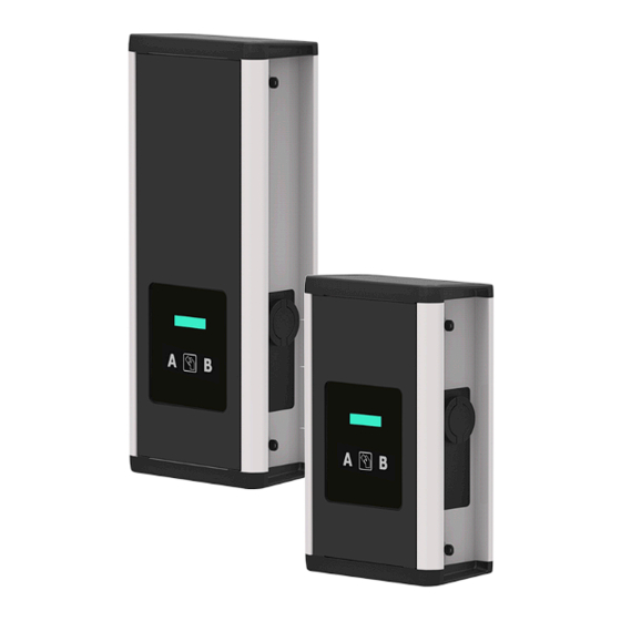
URBAN WB Overview Installation Guide Installation Guide Installation guide Installation Guide Charge Point Installation Guide CirCarLife RFID card Cable Glands URBAN WB key Installation Kit Installation Guide... - Page 11 URBAN WB Master Smart Slave Description RFID Reader Key lock access Plugs Display LCD Wall support Touch screen 8” Base Plugs may vary depending on the model. Installation Guide...
-
Page 12: Dimensions
URBAN WB Dimensions A Small Measures in mm. Installation Guide... -
Page 13: B Large
URBAN WB B Large Measures in mm. Installation Guide... -
Page 14: Installation
URBAN WB Installation Installation Kit: Fixation screw Wall plates • Screws and plastic anchors are NOT INCLUDED. • The installation kit has been tested on a concrete wall. For the unit to be securely fixed in such conditions, it is recommended to use: 8 x Inox A2 wall screws: DIN 7982 Ø4,8x38 o DIN 7981 Ø4,8x38 8 x plastic anchors: 6x30... -
Page 15: A Space Requirements
URBAN WB A Space requirements When installing the unit, some space shall be reserved for usability, maintenance and safety reasons. Please comply accordingly to your country specifications. The next picture shows the minimum distances: 300 mm 500 mm 500 mm Front view. - Page 16 URBAN WB Wall plates: Installation Guide...
-
Page 17: B Plates Fixation
URBAN WB B Plates fixation Install the plates on the wall considering the distances shown on the image below: SMALL LARGE 1000 1000 Measures in mm. Front view Installation Guide... -
Page 18: C Positioning
URBAN WB C Positioning Place the unit on the previously installed wall plates. Installation Guide... -
Page 19: D Opening
URBAN WB D Opening 1.- Use provided key in order to open the unit. 2.- Pull outward the Tamper switch to operate the Charge Point. Tamper Switch: The Charge Point has a security switch (anti-tamper protection) installed that will avoid any charging session if the doors are opened. It has three positions. -
Page 20: E Unit Fixation
URBAN WB E Unit fixation Tighten the provided fixation screw in order to secure the unit to the wall and make sure all components remain as by default before proceeding. Installation Guide... -
Page 21: F Connections
URBAN WB F Connections Introduce connections into the Charge Point: 1.- Remove one or two of the upper or lower plugs that fit your electrical connection (A or B) 2.- Put your electrical connections inside the Charge Point. Put the cable gland according to the chosen plug. -
Page 22: G Wiring
URBAN WB G Wiring URBAN WB with protections included: SINGLE-PHASE CHARGE POINT THREE-PHASE CHARGE POINT • Connect to the 230 V~. Connect to the 400 V~. • • If the Power Supply is Single- Phase, connect L1 and N. • Use provided cable glands in order to •... - Page 23 URBAN WB URBAN WB without protections included: SINGLE-PHASE CHARGE POINT THREE-PHASE CHARGE POINT • Connect to the 230 V~. • Connect to the 400 V~. • The regulation IEC-61851-1 ed 3 indicates • The regulation IEC-61851-1 ed 3 indicates each plug shall have their own protections each plug shall have their own protections upstream.
-
Page 24: H Verification
URBAN WB H Verification 1 . - P O W E R I N P U T Before proceeding, make sure voltage is present in the terminal blocks. For Three-Phase models pay special attention to Neutral Cable. 2 . - M A I N T E N A N C E M O D E Pull outward the Tamper Switch located in the lower half of the Charge Point. - Page 25 URBAN WB Installation Guide...
-
Page 26: Technical Data
URBAN WB Technical Data Master Smart Slave Minimum Output Model Connectors Output Power cable cross Serie current section 2 x Type 2 socket 2 x 32A 2 x 7,4kW 25 mm 2 x Type 2 socket 2 x 32A 2 x 7,4kW 25 mm 2 x Type 2 socket 2 x 32A... - Page 27 URBAN WB GENERAL DATA Serie Light beacon RGB Colour indicator Touch screen 8” Display LCD Multi-language ISO/IEC 14443 A/B MIFARE Classic/DESFire EV1 RFID reader ISO 18092 ECMA-340 NFC 13.56 MHz Meter MID Class 1 - EN 50470-3 Ethernet 10/100BaseTX (TCP-IP) Modem 4G/ 3G /GPRS / GSM Cellular Modem 4G LTE / Wi-Fi Hostpot / 3G / GSM...
- Page 28 URBAN WB Installation Guide...
-
Page 29: Need Help
CIRCUTOR guarantees its products against any manufacturing defect for two years after the delivery of the devices. CIRCUTOR will repair or replace any defective factory product returned during the guar- antee period. • No returns will be accepted and no device will be repaired or replaced if it is not accompanied by a report indicating the defect detected or the reason for the return. - Page 30 URBAN WB Installation Guide...
- Page 31 URBAN WB Installation Guide...
- Page 32 CIRCUTOR S.A.U. Vial Sant Jordi, s/n 08232 - Viladecavalls (Barcelona) Tel: (+34) 93 745 29 00 - Fax: (+34) 93 745 29 14 www. circutor.com central@circutor.com...
Need help?
Do you have a question about the URBAN WB Series and is the answer not in the manual?
Questions and answers